
Advanced CAN-FD Debugging: Solving Transceiver Mysteries
Silent CAN-FD failures, where the controller reports a successful transmission and the oscilloscope shows nothing on the bus, almost always come from the transceiver rather than the protocol engine: a mode pin left in an undefined state, a data-phase bit rate the transceiver cannot hold on the real harness, or missing transmitter delay compensation. On our STM32H562-based sensor node, fixing those three things took frame loss at 2,000 messages per second from 3.2 percent to a fraction of a thousandth of a percent, cut ISR load from 85 percent to 15 percent, and made error recovery a predictable 150 ms instead of over a second. This post walks through the symptoms, the measurements that located each cause, the firmware that fixed them, and the validation that proved it.
The short version
- A CAN-FD transceiver has its own state machine, controlled by mode pins with datasheet-mandated timing; if firmware does not drive those pins in sequence, the controller can “transmit” into a transceiver that is not in normal mode.
- Above about 1 Mbit/s, transmitter delay compensation (TDC) is required, and the data-phase rate must be chosen from oscilloscope measurements on the production harness, not from the datasheet maximum.
- Error handling needs three tiers: FDCAN error counters and bus-off state, the transceiver’s fault pin, and application-level validation.
- Validate with the real harness, real temperatures and real load; the failures here were invisible on the bench.
The challenge: silent failures in a production-ready system
Our multi-sensor edge platform combines camera capture, thermal imaging and proximity sensing, coordinated over a CAN-FD network at data rates chosen for real-time processing. It hit an intermittent reliability problem: CAN-FD frame transmission failures that appeared only under high load.
The symptoms did not point anywhere obvious. Frames appeared to transmit successfully with no FDCAN errors reported. Oscilloscope traces showed silence on the bus during those “successful” transmissions. Error recovery triggered sporadically with no pattern. And above roughly 2,000 messages per second the node went bus-off.
Hardware foundation
The node pairs an STM32H562AII6 with an automotive-grade CAN-FD transceiver, targeting a 1 Mbit/s nominal (arbitration) rate, a 5 Mbit/s data phase for sensor data, operation from minus 40 to plus 85 degrees Celsius, and frame loss well under 0.01 percent.
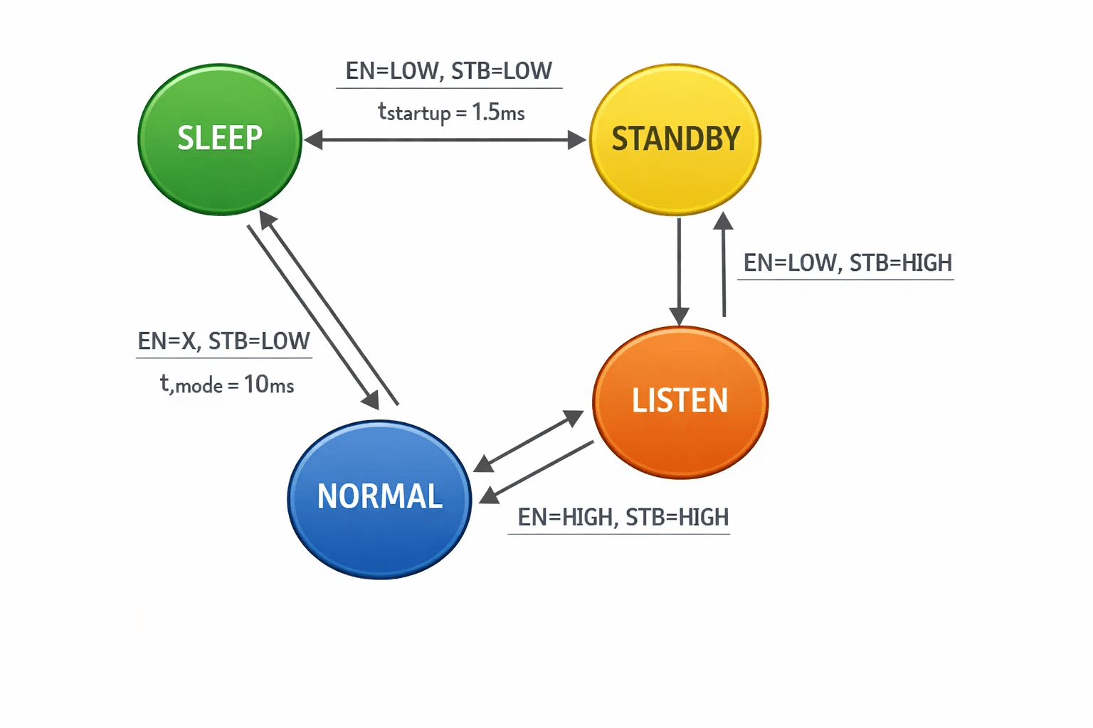
Unlike simple transceivers that run in one fixed mode, this class of part exposes mode control pins (standby and enable) that select sleep, standby, listen-only or normal operation, and it holds separate state machines for system control and for CAN protocol handling. That separation is the root of most “mysteries”: the FDCAN peripheral can be fully initialized and running while the transceiver is still in standby, and nothing in the controller’s status registers will say so.
typedef enum {
    TRANSCEIVER_MODE_SLEEP = 0,   // Minimal power consumption
    TRANSCEIVER_MODE_STANDBY = 1, // Wake-capable, low power
    TRANSCEIVER_MODE_LISTEN = 2,  // Receive-only operation
    TRANSCEIVER_MODE_NORMAL = 3   // Full transceiver operation
} TransceiverMode_t;

static HAL_StatusTypeDef SetTransceiverMode(TransceiverMode_t mode) {
    GPIO_PinState stb_pin = GPIO_PIN_SET;
    GPIO_PinState en_pin = GPIO_PIN_RESET;

    switch (mode) {
        case TRANSCEIVER_MODE_NORMAL:
            stb_pin = GPIO_PIN_SET; en_pin = GPIO_PIN_SET; break;
        case TRANSCEIVER_MODE_LISTEN:
            stb_pin = GPIO_PIN_SET; en_pin = GPIO_PIN_RESET; break;
        case TRANSCEIVER_MODE_STANDBY:
            stb_pin = GPIO_PIN_RESET; en_pin = GPIO_PIN_RESET; break;
        case TRANSCEIVER_MODE_SLEEP:
            stb_pin = GPIO_PIN_RESET; en_pin = GPIO_PIN_SET;
            HAL_Delay(1); // Datasheet-mandated transition delay
            break;
    }

    HAL_GPIO_WritePin(STB_GPIO_Port, STB_Pin, stb_pin);
    HAL_GPIO_WritePin(EN_GPIO_Port, EN_Pin, en_pin);
    HAL_Delay(10); // Mode stabilization period

    return HAL_OK;
}
The key insight: atomic GPIO operations with the mandatory delays prevent transceiver state machine corruption during mode transitions.
Symptom to cause: a diagnostic table
The table below is the one we wish we had on day one. Each row is a symptom we observed, the measurement that separated the candidate causes, and the cause it turned out to be.
The debugging method, phase by phase
Phase 1: signal integrity at the data-phase rate
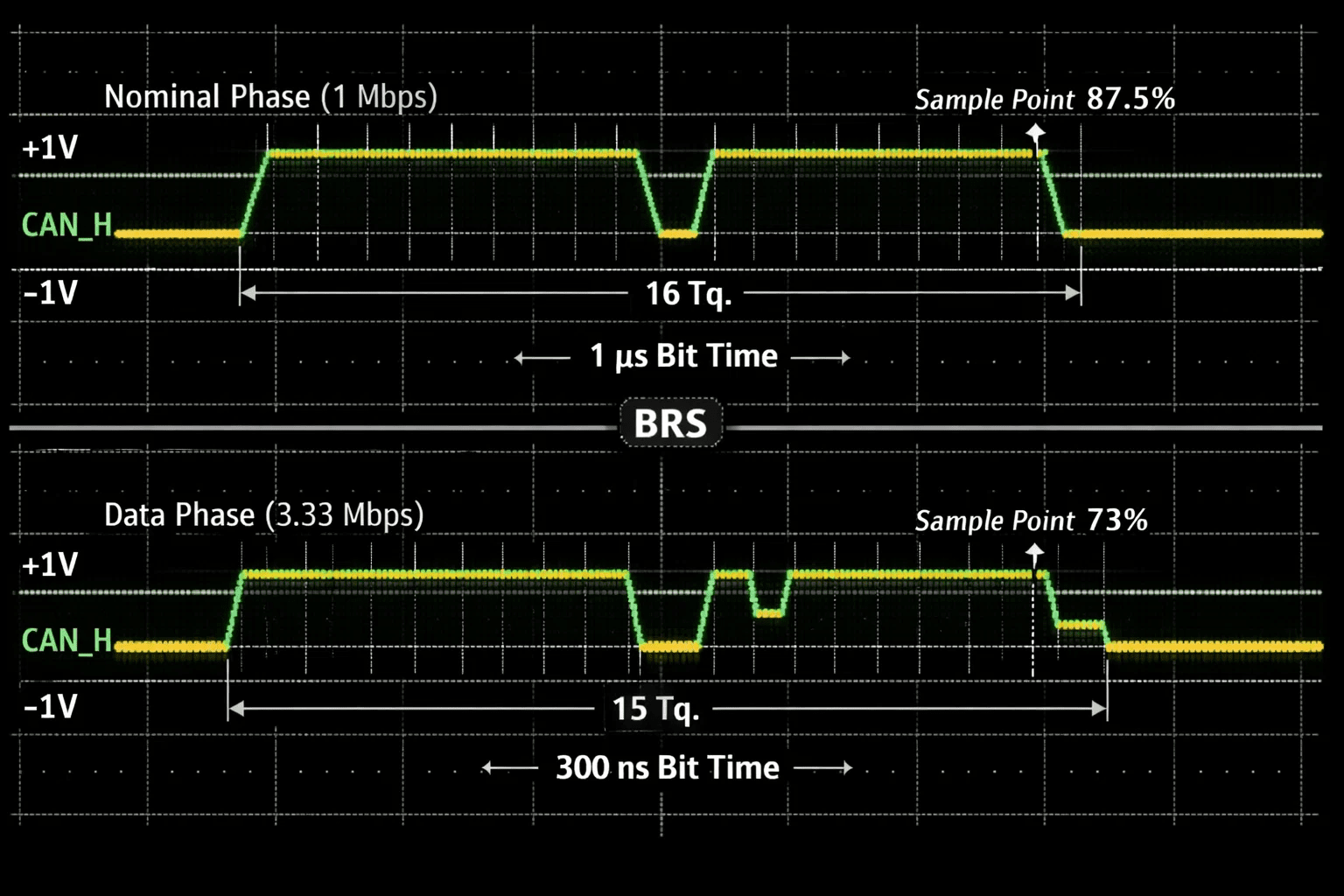
Oscilloscope analysis showed signal integrity degradation at high data rates: the original 5 Mbit/s target suffered reflection artifacts that caused intermittent bit errors on the production harness. We settled on a conservative 3.33 Mbit/s data phase with larger sample-point margins and enabled transmitter delay compensation, measuring the loop delay rather than guessing it.
// STM32H5 FDCAN Configuration - Production Optimized
hfdcan1.Init.NominalPrescaler = 16;     // 250 MHz / 16 = 15.625 MHz tq
hfdcan1.Init.NominalTimeSeg1 = 13;      // Sample point = 87.5%
hfdcan1.Init.NominalTimeSeg2 = 2;
hfdcan1.Init.NominalSyncJumpWidth = 1;

hfdcan1.Init.DataPrescaler = 5;         // 250 MHz / 5 = 50 MHz tq
hfdcan1.Init.DataTimeSeg1 = 10;         // Sample point = 73%
hfdcan1.Init.DataTimeSeg2 = 4;
hfdcan1.Init.DataSyncJumpWidth = 4;     // Maximum tolerance

// Critical: Enable Transceiver Delay Compensation
hfdcan1.Init.TxDelayCompensation = ENABLE;
hfdcan1.Init.TxDelayCompensationOffset = 0x40; // Measured loop delay
Phase 2: transceiver state management
The second breakthrough was understanding that the transceiver keeps independent state machines for system control and CAN protocol handling. Improper initialization left it in undefined states. Mode transitions have to follow datasheet timing exactly, and the fault pin has to be monitored. The order matters: start the controller before switching the transceiver to normal mode, so the first thing the bus sees from this node is a valid recessive idle, not a partially configured peripheral.
static bool CheckTransceiverFault(void) {
    return (HAL_GPIO_ReadPin(FAULT_GPIO_Port, FAULT_Pin) == GPIO_PIN_RESET);
}

int InitializeTransceiverSequence(void) {
    // Step 1: Reset to known state
    SetTransceiverMode(TRANSCEIVER_MODE_SLEEP);
    HAL_Delay(2);

    // Step 2: Configure FDCAN peripheral
    if (HAL_FDCAN_Init(&hfdcan1) != HAL_OK) return -1;

    // Step 3: Enable interrupts and filters
    ConfigureFDCANFilters();
    HAL_FDCAN_ActivateNotification(&hfdcan1, FDCAN_IT_RX_FIFO0_NEW_MESSAGE);

    // Step 4: Start peripheral then activate transceiver
    HAL_FDCAN_Start(&hfdcan1);
    SetTransceiverMode(TRANSCEIVER_MODE_NORMAL);
    HAL_Delay(50);

    // Step 5: Verify successful initialization
    return CheckTransceiverFault() ? -1 : 0;
}
Phase 3: three-tier error handling
A single error path is not enough. We combine FDCAN hardware monitoring, transceiver fault signaling and application-level validation. RX FIFO overflow is handled by draining and discarding pending messages while incrementing an overflow counter, rather than letting the buffer corrupt:
if (RxFifo0ITs & FDCAN_IT_RX_FIFO0_FULL) {
    while (HAL_FDCAN_GetRxFifoFillLevel(hfdcan, FDCAN_RX_FIFO0) > 0) {
        FDCAN_RxHeaderTypeDef discardHeader;
        uint8_t discardData[64];
        HAL_FDCAN_GetRxMessage(hfdcan, FDCAN_RX_FIFO0, &discardHeader, discardData);
    }
    IncrementOverflowCounter();
}
Bus-off recovery coordinates the controller and the transceiver: stop the controller, drop the transceiver to standby, wait out a bus idle period, then restart both.
void HandleFDCANError(void) {
    uint32_t ecr = hfdcan1.Instance->ECR;
    uint32_t txErrorCount = ecr & 0xFF;
    uint32_t rxErrorCount = (ecr >> 8) & 0x7F;

    if (hfdcan1.Instance->PSR & FDCAN_PSR_BO) {
        HAL_FDCAN_Stop(&hfdcan1);
        SetTransceiverMode(TRANSCEIVER_MODE_STANDBY);
        HAL_Delay(100);
        SetTransceiverMode(TRANSCEIVER_MODE_NORMAL);
        HAL_FDCAN_Start(&hfdcan1);
        LogErrorRecovery(txErrorCount, rxErrorCount);
    }
}
The SPI-attached external controller we use elsewhere has its own version of these failure modes; the MCP2518FD debugging diary covers them, and the host-side receive problems at saturation are in catching a CAN FD firehose: a lossless receiver on Linux.
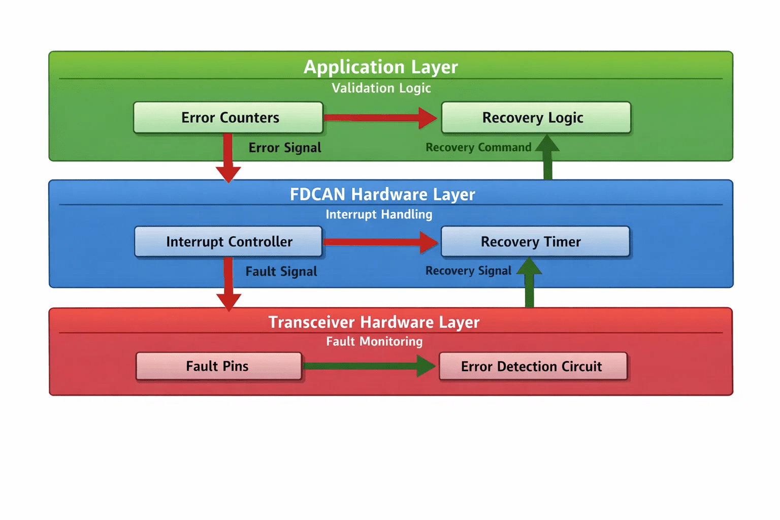
Bus-off recovery needs coordination between the FDCAN controller and the transceiver: stop the controller, drop the transceiver to standby, wait out a bus idle period, then restart both fresh:
CAN-FD payload optimization
CAN-FD’s non-linear DLC mapping needs careful payload size handling. DLC values 0 to 8 mean 0 to 8 bytes; 9 to 15 mean 12, 16, 20, 24, 32, 48 and 64 bytes.
static uint8_t DecodeFDCANDLC(uint32_t dlc) {
    const uint8_t dlcMap[16] = {0,1,2,3,4,5,6,7,8,12,16,20,24,32,48,64};
    return (dlc <= 15) ? dlcMap[dlc] : 8; // Safe fallback
}
Choosing the most efficient DLC for a payload reduces bus utilization by roughly 15 to 20 percent for typical sensor payloads while staying protocol-compliant. Designing message layouts so that growth lands on a DLC step is covered in CAN messages as contracts.
Production validation: before and after
Extended validation covered 72 hours of continuous stress testing with over a million CAN-FD frames and no CRC errors, temperature cycling from minus 40 to plus 85 degrees Celsius during operation, EMC compliance testing with production cable harnesses, and power supply variation under maximum load. The general bring-up sequence for the bus, from bit timing to driver design, is in Understanding CAN FD: from theory to production firmware.
A checklist before you blame the protocol
- Probe TXD, RXD and the differential bus together. If TXD toggles and the bus does not, the transceiver is not in normal mode.
- Read the transceiver datasheet’s mode table and transition timings, and drive the pins in that order with those delays.
- Measure loop delay and set TDC before raising the data-phase rate above 1 Mbit/s.
- Choose the data-phase rate from an eye diagram on the production harness at the farthest node, not from the datasheet maximum.
- Log ECR counters and the PSR bus-off bit in the error ISR; recovery must reset the transceiver, not only the controller.
- Keep the RX ISR to copying frames out of the FIFO; do the work elsewhere.
- Run the stress test with the real harness, the real enclosure and the real temperature range.
Why it matters at Hoomanely
The sensor network behind EverBowl™ runs on this bus, and the record EverBowl builds of how a dog eats and drinks depends on every one of those frames arriving. A bus that loses 3 percent of frames under load is a record with holes in it. EverBowl does not diagnose anything; the value is the record, and the record is only as good as the link that carries it. More firmware posts are in the firmware category.
Conclusion
Transceiver mysteries stop being mysteries once you treat the transceiver as a device with its own state, its own timing and its own fault output. Drive its mode pins in the datasheet order, measure loop delay and enable TDC, pick the data-phase rate from the harness rather than the headline number, and recover from bus-off by resetting both halves of the link. Then prove it with 72 hours on the real hardware.
FAQs
Why does my CAN FD controller report success while the bus is silent?
Because the controller only sees TXD and RXD at its own pins. If the transceiver is in standby or an undefined mode, it does not drive the bus, and the controller cannot tell. Probe the differential bus and the transceiver mode pins together.
What is transmitter delay compensation and when is it needed?
TDC shifts the point at which the transmitting node samples its own bit to account for the transceiver loop delay. It is required for data-phase rates above about 1 Mbit/s; without it the node sees its own bits as errors and the error counters climb.
Why did a 5 Mbit/s data phase fail on the real harness?
Reflections from stubs and connectors corrupt bits at higher rates. The datasheet maximum assumes an ideal bus; the production harness set a stable limit of 3.33 Mbit/s in our case, confirmed with an eye diagram at the farthest node.
How should bus-off recovery be handled with a mode-controlled transceiver?
Stop the controller, put the transceiver in standby, wait out a bus idle period (we use 100 ms), return the transceiver to normal mode, then restart the controller. Restarting only the controller leaves the transceiver in its fault state.
How do I measure the TDC offset value?
Transmit a dominant bit, measure the delay between the TXD falling edge and the RXD falling edge at the controller pins, convert it to data-phase time quanta and add a margin of about half a bit time. Enter that as the compensation offset.
What validation proves a CAN FD link is production ready?
A long soak at the target message rate with zero CRC errors (we ran 72 hours and over a million frames), temperature cycling across the rated range while running, EMC testing with the production harness, and supply variation under maximum load.



