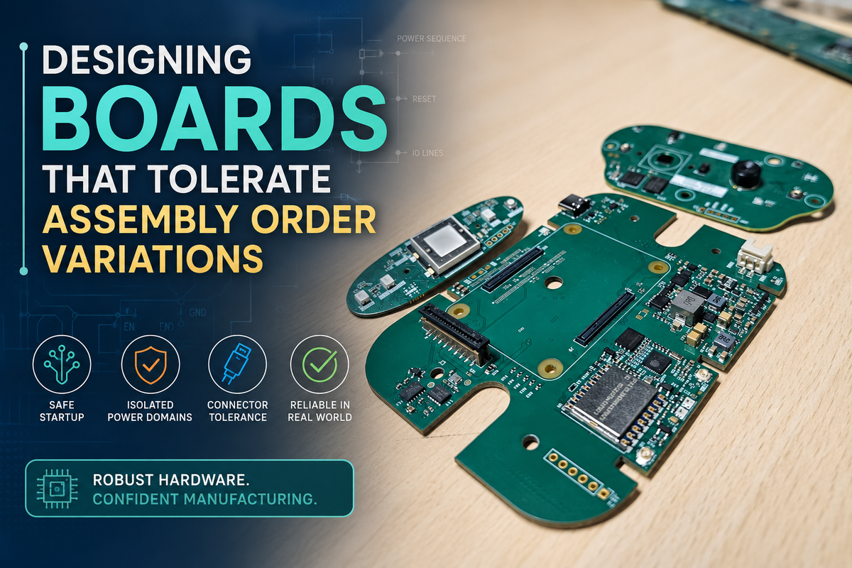
Designing Boards That Tolerate Assembly Order Variations: A Guide to Hardware Resilience
In the early stages of hardware development, it is incredibly common for engineers to imagine assembly as a perfectly linear, flawless process. In this idealised world, components arrive exactly on time, boards get populated in a strict sequence, firmware is flashed immediately after assembly, cables are connected correctly, and every single subsystem powers on exactly when expected. On paper, the process looks impeccably clean.
Reality, however, rarely behaves that way.
In actual manufacturing environments—especially during rapid scaling, repair handling, EVT/DVT/PVT transitions, or contract manufacturing transfers—assembly order variations become one of the most heavily underestimated sources of system instability. A printed circuit board (PCB) that works perfectly on a pristine lab bench may suddenly behave unpredictably when a sensor board powers up before the primary microcontroller unit (MCU), when one module is connected before another, or when a ribbon cable is inserted while power rails are partially active.
These failures are rarely dramatic explosions or magic smoke. Instead, they appear as frustratingly inconsistent boot behaviours, random current spikes, partial system initialisations, communication lockups, or devices that only fail sometimes on the production line. The most maddening part for an engineer? The schematic may still be perfectly correct from a purely electrical standpoint.
The root issue is a lack of architectural tolerance.
The Golden Rule of Hardware Resilience: Good hardware does not assume a perfect assembly sequence. It survives imperfect sequencing gracefully.
At Hoomanely, this principle became glaringly apparent while developing modular systems around the EverBowl architecture. Different compute modules, sensor boards, wireless interfaces, and power subsystems often evolved entirely independently during bring-up. Some modules were assembled weeks earlier than others. Some PCBs arrived from fabrication long before their companion boards. Some units entered the debugging phase with partially connected wire harnesses or makeshift prototype adapters.
The systems that ultimately behaved the most reliably were never the ones with the most complex, clever circuitry. They were the systems intentionally designed to tolerate uncertainty in assembly and power-up sequences.
This comprehensive guide explores how hardware can be architected to remain rock-solid even when assembly order deviates, connectors are inserted entirely out of sequence, or subsystems wake up unpredictably during manufacturing and field servicing.
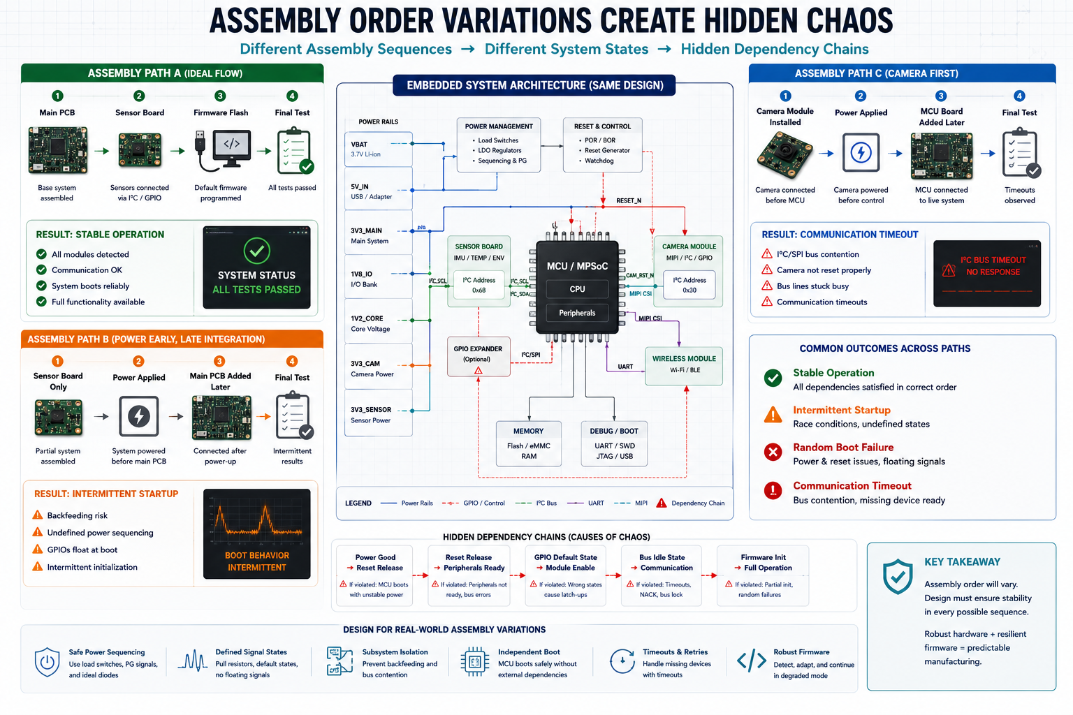
Why Assembly Order Variations Create Hidden Chaos
Modern embedded systems are deeply and intricately interconnected. Power rails, general-purpose input/outputs (GPIOs), reset lines, communication buses, and boot configuration pins frequently cross boundaries between multiple boards. This deep integration creates hidden dependencies that are invisible on a high-level block diagram.
A dedicated sensor module might inherently expect the main processor rail to be stable before its I/O buffers become active. A wireless module might aggressively drive UART lines high before the host MCU has even finished its boot ROM execution. A Power Management IC (PMIC) might enter an entirely undefined state if its enable pins are left floating during partial system assembly.
When assembly happens differently than expected, these fragile assumptions instantly collapse.
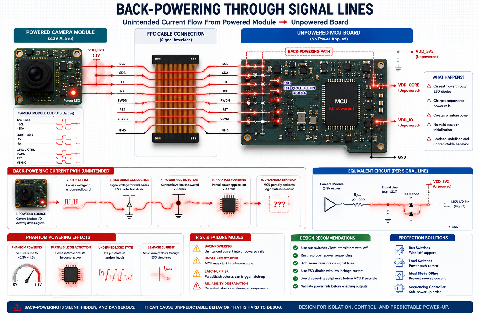
One of the most notoriously common examples is back-powering through signal lines.
Imagine a high-resolution camera board connected to a mainboard via a flexible printed circuit (FPC) cable. The processor board is currently unpowered, but the camera module receives auxiliary power first during a specific bench test. If communication lines like UART, I2C, or CSI lanes contain standard internal Electrostatic Discharge (ESD) protection diodes tied to their local internal rails, current can flow backward from the camera, through the signal lines, across the ESD diodes, and into the processor's power domain.
The processor is technically turned "off," but isolated portions of its internal silicon become partially energised. This phantom powering leads to severe consequences:
- Undefined logic states: Internal gates sit at intermediate voltage levels.
- Incomplete resets: Watchdog timers and power-on resets fail to trigger cleanly.
- High leakage currents: Components draw excessive power, leading to localised heating.
- Boot ROM corruption: The processor boots into unknown or test states.
- Bus contention: Multiple devices attempt to drive the same lines simultaneously.
- Latch-up risks: Parasitic thyristors in the CMOS structure can short VDD to ground.
The failure may disappear entirely once full assembly happens in the intended order, making root-cause debugging incredibly difficult. The board appears inherently unreliable, even though the real culprit is a lack of sequencing tolerance.
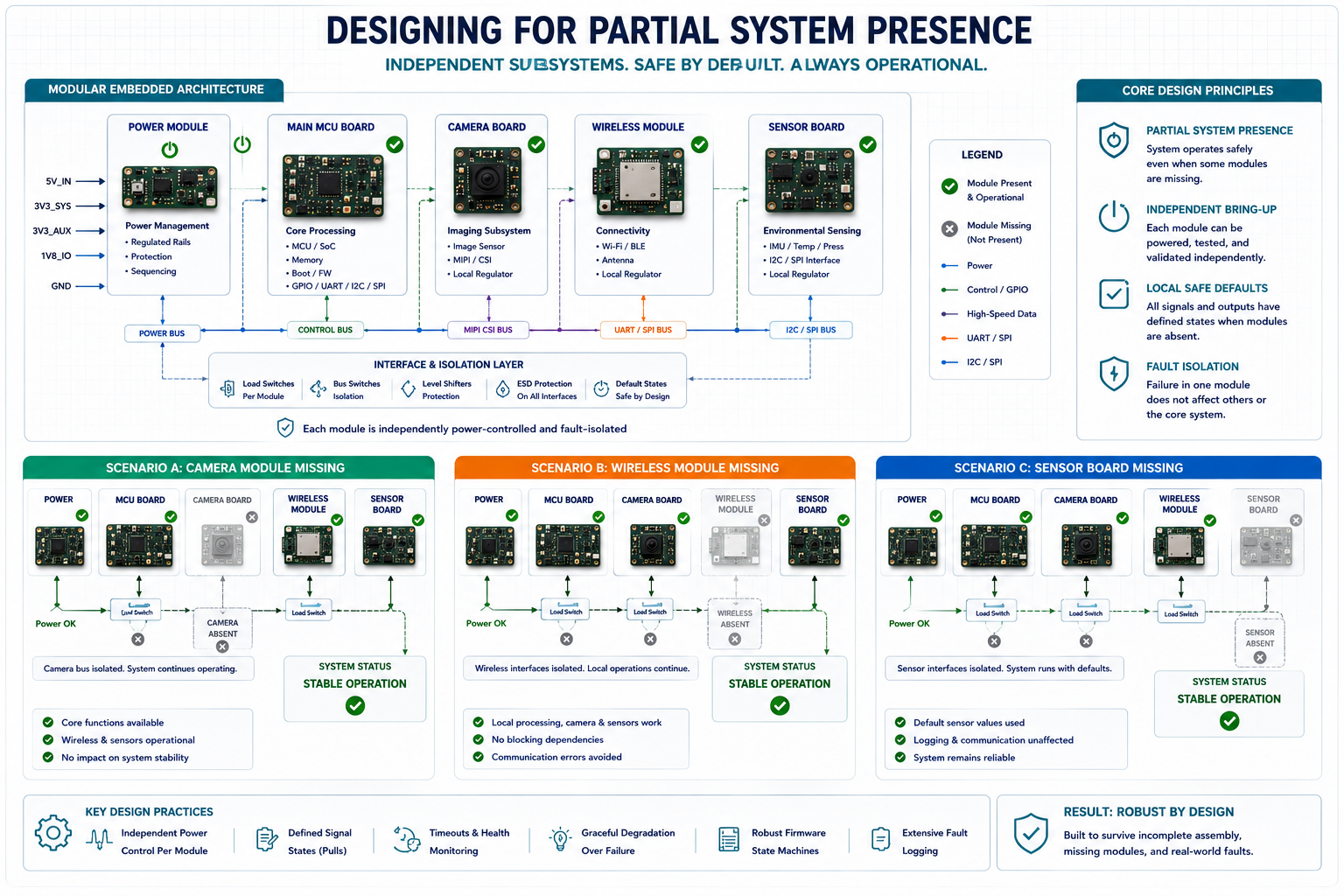
Designing for Partial System Presence
One of the most vital mindset shifts a hardware engineer can make is designing for partial presence. Every single subsystem must behave safely—electrically and logically—even if its neighbouring subsystems are entirely absent, significantly delayed, unpowered, or only partially connected.
This core principle fundamentally changes how hardware interfaces are designed. Instead of assuming a connected peripheral will always be there, the hardware must be hardened to tolerate:
- Floating communication buses
- Delayed power rail arrival
- Connector hot-plugging during active debug sessions
- Partial or incomplete harness assembly
- Total absence of application firmware
- Uninitialized or high-impedance GPIO states
- Missing companion modules during the manufacturing flow
In EverBowl’s highly modular architecture, several development boards were intentionally designed to operate fully independently long before full-stack integration occurred. That meant each discrete subsystem required deeply stable, localised defaults rather than relying on the main application firmware to set the rules.
The difference in system stability was staggering. Boards became testable weeks earlier. Manufacturing line diagnostics vastly improved. Complex integration failures became trivial to isolate. Most importantly, those dreaded, unstable "sometimes" failures were reduced dramatically.
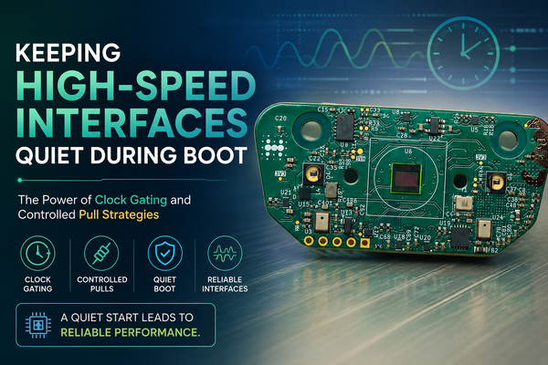
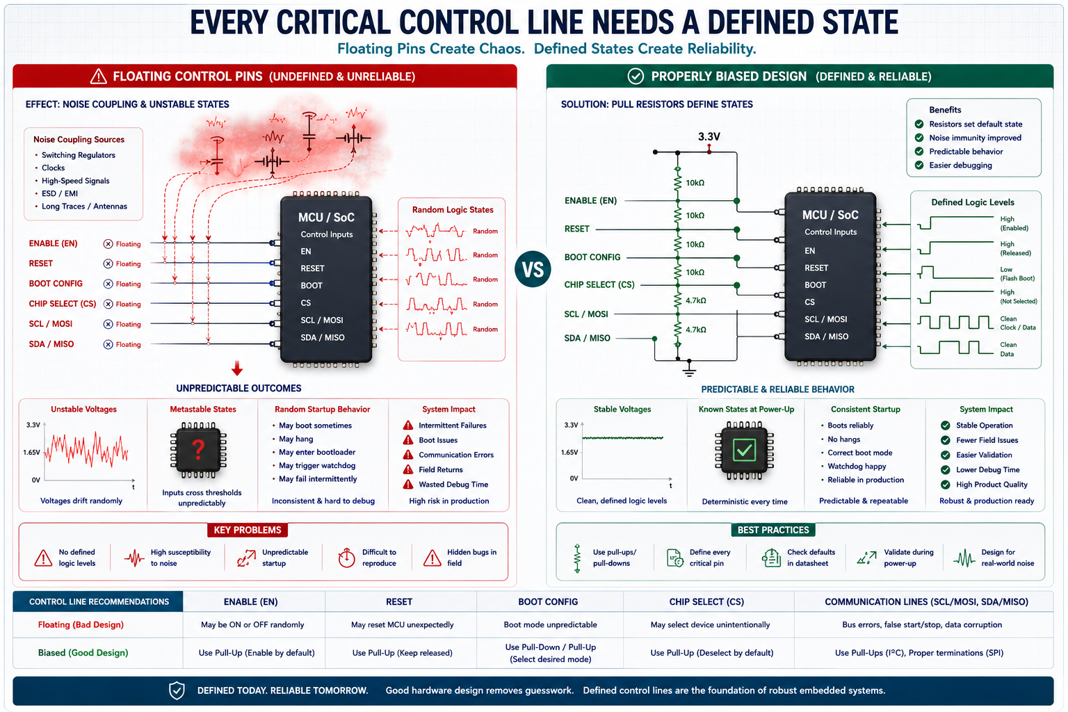
Mitigating the Danger of Floating Control Lines
Assembly-order instability frequently originates from a single, uncontrolled logic pin. Enable pins, system reset lines, boot mode selectors, interrupt outputs, and power-good signals are almost always assumed to be actively driven by a master controller. During real-world manufacturing conditions, however, these lines may float in a high-impedance state for seconds, minutes, or even hours.
Floating control pins create incredibly unpredictable states because standard CMOS inputs consume virtually zero current. Their internal gate capacitance can easily drift toward undefined middle-voltage thresholds due to ambient electromagnetic noise or microscopic board leakage.
This directly causes wildly inconsistent startup behaviour. A floating enable pin on a buck regulator may cause it to oscillate violently during a rail ramp-up. A floating reset line may keep critical peripherals trapped in a half-initialised zombie state. A floating boot configuration pin might accidentally place a production MCU into a factory programming mode.
The solution to this is deceptively simple, yet frequently overlooked: Every critical control line must have a rigidly deterministic default state.
| Design Element | Best Practice Implementation |
| Enable Pins | Always include physical pull-ups or pull-downs to establish an "off" or safe default. |
| Reset Lines | Bias heavily toward the active-reset state until explicitly released by a stable source. |
| Boot Configuration | Hardwire defined boot defaults using physical resistor strapping. |
| Chip Selects (CS) | Ensure SPI or memory CS lines are pulled to their inactive state locally. |
| Comms Interfaces | Design idle-safe communication lines that do not trigger false start bits. |
The most critical detail here is that these defaults must exist electrically. They cannot depend on firmware execution. Stability must exist physically before a single line of software begins to run.
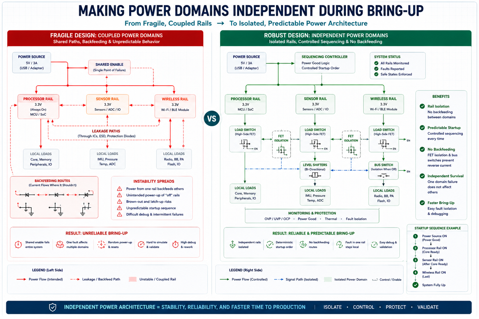
Making Power Domains Independent During Bring-Up
A major cause of sequencing-related catastrophic failures is excessive, undocumented coupling between different power domains. In poorly isolated architectural layouts, one power rail indirectly controls or influences another through signal line leakage, shared enable logic trees, or internal protection structures.
When domains are tightly coupled, power-up timing becomes incredibly fragile. Partial startup states become physically dangerous to the silicon. Debugging becomes inconsistent, and eventual field servicing becomes a high-risk operation.
A much more resilient design treats every power domain as independently survivable. Rails should never backfeed one another. Disabled domains must remain electrically quiet. Interfaces must tolerate one side being fully unpowered without drawing current, and signal paths must aggressively avoid parasitic powering.
To achieve this level of isolation, engineers should utilise:
- Series resistors: Placed on inter-board signals to limit potential back-drive current.
- Level shifters: Specifically choosing models with guaranteed high-impedance isolation when power is lost on either side.
- Bus switches: To physically disconnect I2C or SPI lines until both sides are verified ready.
- Power sequencing supervisors: Dedicated hardware ICs to manage rail timing reliably.
- FET-based domain isolation: Using MOSFETs to physically cut off power to entire subsystems.
The goal is not merely to prevent permanent hardware damage. The true goal is maintaining absolute predictability. A predictable, hard failure is infinitely easier to diagnose and fix than an intermittent, occasional success.
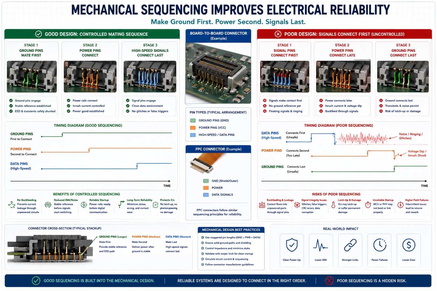
The Physical Interface: Connector Sequencing Matters
Connectors introduce an entirely separate layer of assembly-order complexity. In many systems, connectors are mated physically in ways the designer never anticipated. Ground pins may make contact milliseconds after active signal lines. High-current power may arrive before the reference return paths have stabilised. Long FPC cables can capacitively inject sharp voltage transitions into neighbouring sensitive lines during the physical act of insertion.
Professional, high-reliability systems often solve this by utilising staged (or sequenced) connectors.
Standard Staged Connector Mating Sequence:
- Ground pins mate first: Establishing a common reference and safe return path for ESD.
- Power pins mate second: Energising the circuitry safely.
- High-speed signals mate last: Ensuring data lines only connect when the transceivers are fully powered and stable.
This mechanical sequencing dramatically improves hot-plug tolerance and completely eliminates transient instability. Even if your budget does not allow for specialised staged connectors, engineers can heavily improve robustness through strategic PCB layout decisions.
Place your grounds immediately adjacent to sensitive signals. Physically separate high-current power lanes from high-speed data lanes. Avoid routing exposed, sensitive control pins near the physical edges of a connector where they might be touched first. Add inline damping resistors near interfaces, and generously use Transient Voltage Suppression (TVS) diodes wherever insertion transients are expected.
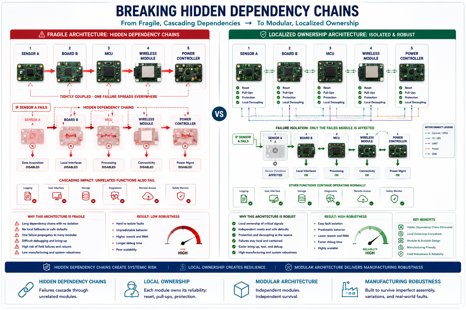
Breaking Hidden Dependency Chains
One of the most dangerous, insidious patterns in embedded hardware is the hidden dependency chain. This occurs when subsystem A silently depends on subsystem B being perfectly initialised first, even though this critical relationship is entirely undocumented in the schematic.
Examples of fragile dependency chains include routing a sensor's reset line through a completely separate, unrelated module, or requiring a third, optional board to provide the physical pull-up resistors for an I2C bus.
These highly coupled architectures may appear efficient on paper, saving a few resistors or routing channels, but they become terrifyingly fragile during manufacturing variations. If one single board is delayed on the assembly line, temporarily disconnected for rework, or partially assembled, entirely unrelated sections of the product will stop functioning.
The superior approach is localised ownership. Each discrete subsystem should ideally own its own reset defaults, its own pull-up/pull-down structures, its own local bulk decoupling, and its own protection behaviour. Distributed dependency chains destroy modularity and drastically increase a product's sensitivity to the manufacturing environment.
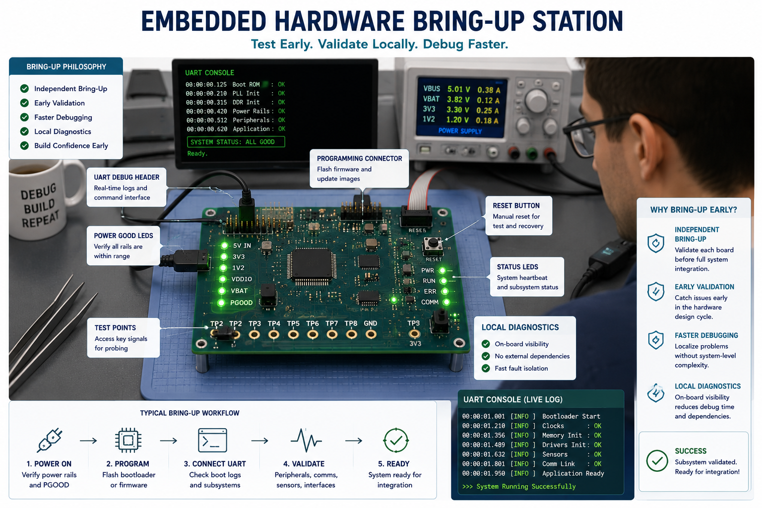
Designing for Debugging Before Full Integration
Far too many boards are validated only after complete, final integration. This creates a massive bottleneck because when the system fails to boot, the failures are nearly impossible to isolate. A much more scalable approach is designing each subsystem for immediate, independent bring-up.
A well-designed board should expose enough physical observability to answer basic diagnostic questions even before the rest of the system is plugged in.
Consider adding local power-good indicator LEDs for every major rail. Expose accessible UART test points that stream status data immediately. Include independent programming headers for secondary MCUs. Add physical tactile buttons for local resets, and ensure default boot modes can be triggered without relying on upstream software.
During the EverBowl development cycle, early hardware bring-up became exponentially faster once individual modules could self-identify their power state without waiting for the host processor to ask them. Instead of the team sitting around a bench asking, "Why doesn’t the system boot?" they could instantly look at the boards and ask, "Why did the vision subsystem fail to achieve power-good?"
That distinct shift in observability changes debugging efficiency completely.
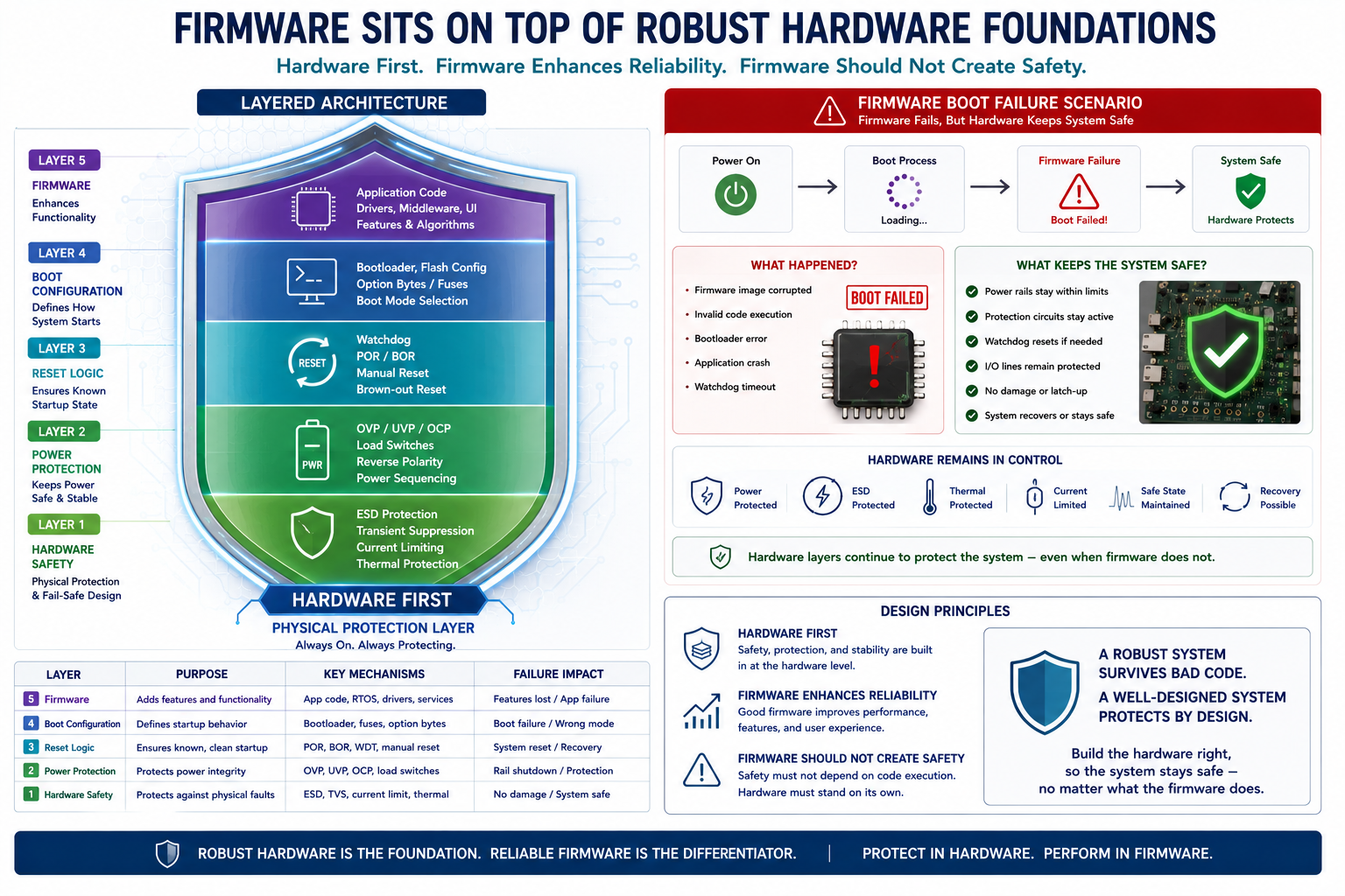
Firmware Cannot Be Your Only Safety Layer
A deeply entrenched trap in electrical engineering is assuming that the firmware team will simply initialise the hardware correctly and fix any floating states in software.
During assembly-order variations and manufacturing hiccups, the firmware may never even execute.
Voltage brownouts, unstable crystal oscillators, undefined hardware reset states, and partially powered MCU domains can easily prevent the bootloader from ever running. Therefore, the hardware itself must remain intrinsically safe prior to any firmware intervention.
Regulators must default to safe, low-voltage, or "off" states. Boot selector pins must never be allowed to float. Communication interfaces should never actively drive unknown logic levels into sleeping chips. Current paths must remain strictly bounded by hardware limits.
Firmware is there to enhance system robustness and provide features. It should never be tasked with creating the first and only layer of physical hardware safety.
Embracing Graceful Imperfection in Manufacturing
Perhaps the biggest lesson in hardware engineering is the realisation that manufacturing environments are fundamentally human systems.
Circuit boards are handled by human technicians working under strict time pressure. Complex assemblies are interrupted by breaks or shift changes. Board reworks happen mid-process. Ribbon cables are inserted slightly askew. Modules are swapped and replaced individually to test failures.
The absolute best hardware acknowledges this messy, human reality rather than stubbornly resisting it. A truly resilient board does not demand perfectly sterile handling and flawless sequencing to survive the day.
At Hoomanely, some of the most incredibly valuable architectural improvements did not come from running SPICE simulations. They came from standing on the factory floor, observing exactly how real technicians interacted with prototype hardware during bring-up, testing, and debugging. The overarching goal was never simply electrical correctness. It was operational, real-world tolerance.
Perfect assembly order is a complete illusion. Real-world systems will always experience delayed power rails, missing peripherals, temporarily unstable interfaces, and inconsistent sequencing throughout their entire lifecycle. Boards designed strictly for the pristine conditions of an engineering lab will inevitably become fragile nightmares in the field. But boards explicitly designed to handle imperfect conditions? Those become legendary, scalable products.