Designing Hardware Crosstalk Budgets for Dense High-Speed Connector Pinouts
Why pin assignment is not just routing convenience
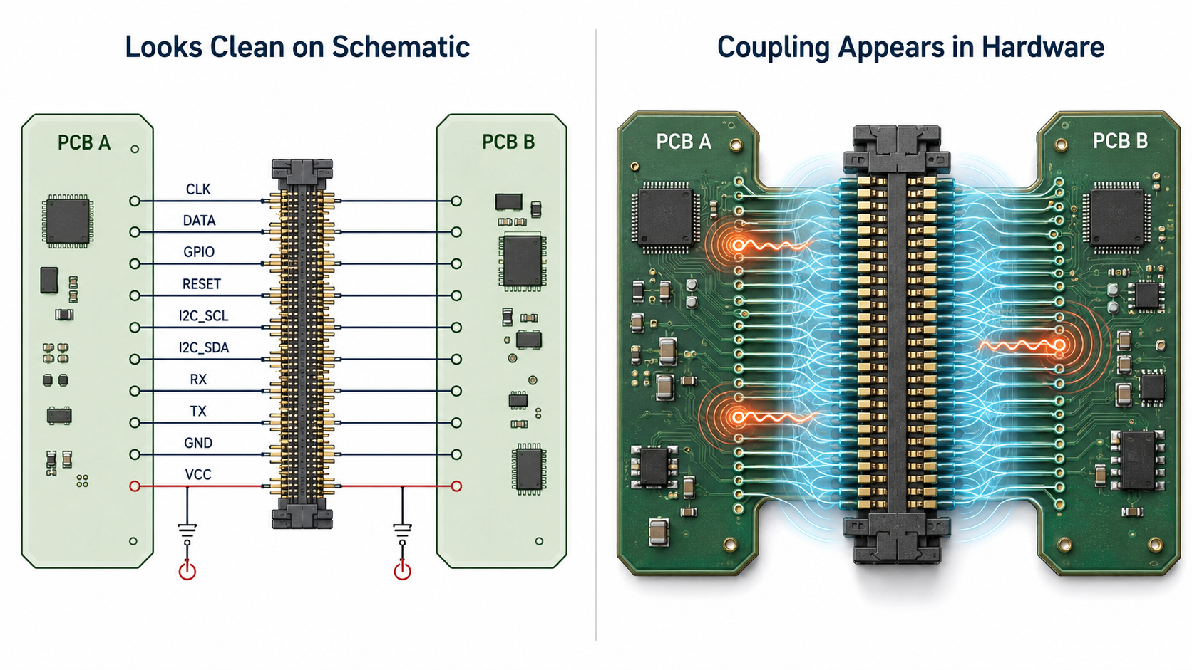
Dense connectors look harmless on a schematic.
A row of pins.
A few high-speed lanes.
Some power.
Some ground.
A few control signals.
Maybe an I2C bus, reset, interrupt, enable lines, and one or two spare pins.
Everything fits.
Then the board comes back.
The interface works most of the time, but not always. Camera frames drop occasionally. A high-speed link trains at a lower rate. A sensor board fails only with a longer cable. A reset line gets false pulses when data traffic starts. A low-speed configuration bus behaves differently when the high-speed interface is active.
At that point, the issue is no longer whether the connector has enough pins.
The issue is whether the connector pinout was designed with a crosstalk budget.
At Hoomanely, we treat connector pin assignment as part of the electrical architecture, not as a late-stage routing decision. In modular systems, the connector is not just a mechanical bridge. It is where power integrity, signal integrity, return paths, assembly tolerance, and system ownership all meet.
A dense connector can make a product elegant.
A careless dense connector can make the product unreliable in ways that are extremely difficult to debug.
A Connector Pinout Is an Electrical Layout
One mistake we avoid is treating connector pinout as a table-filling exercise.
It is easy to start with a list of required signals and simply assign them to available pins. But high-speed connector design does not work that way. Every pin has electrical neighbours. Every signal has a return path. Every fast edge has fields around it. Every ground pin affects the quality of multiple nearby signals.
The connector is effectively a miniature transmission-line environment.
If a fast clock is placed beside a reset line, the reset line may see unwanted coupling. If two high-speed lanes sit next to each other without a clean return structure, their edges can influence each other. If a low-speed interrupt line is routed through a noisy connector region, it may behave cleanly in firmware logs but fail electrically during transitions.
This is why pinout must be planned before layout pressure begins.
Once the board is routed and the connector is selected, fixing crosstalk problems often means painful changes: connector remapping, cable changes, impedance adjustments, shielding changes, or full PCB revision.
Good architecture prevents that early.
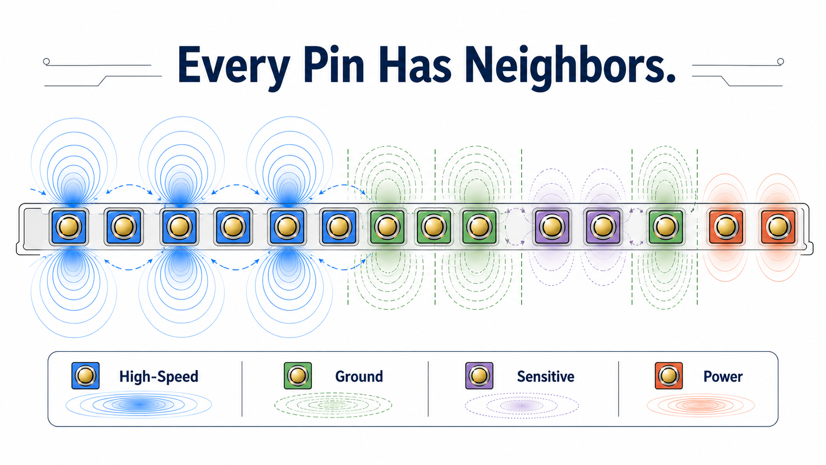
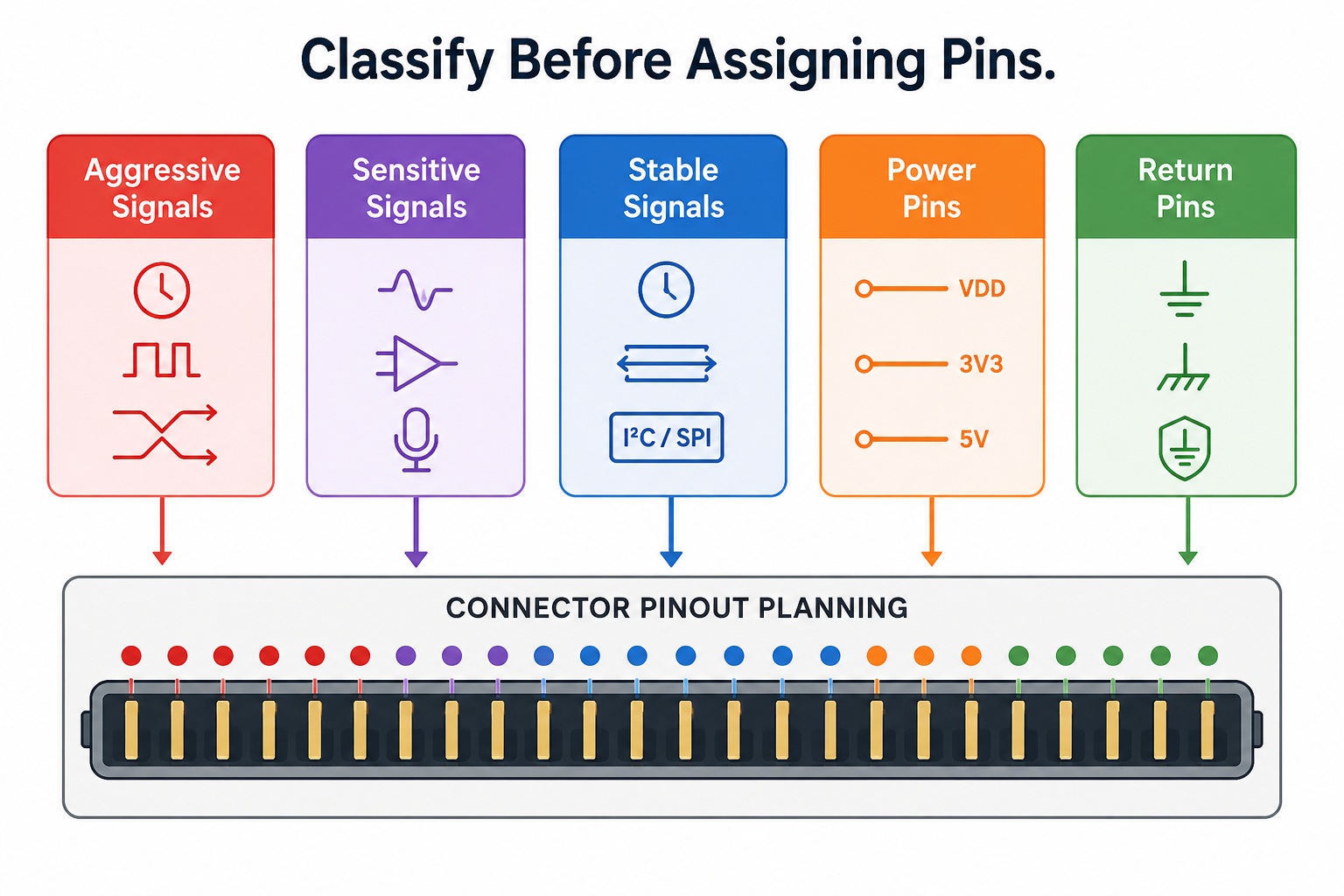
Crosstalk Budgeting Starts With Signal Classification
Before assigning connector pins, we classify signals by behaviour, not just name.
A line called “CLK” is not just a clock. It has edge rate, frequency, duty cycle, swing, source impedance, and sensitivity around it. A line called “RESET” may be low speed, but it may be extremely sensitive because a short disturbance has system-wide consequences.
A practical Hoomanely-style connector review separates signals into groups:
- Aggressive signals: clocks, high-speed data, fast switching enables, PWM, high-current control edges.
- Sensitive signals: reset, boot straps, interrupts, analog references, detect pins, sensor timing lines.
- Stable signals: static configuration, presence detect, ID pins, slow status lines.
- Power pins: input rails, switched rails, sensor rails, auxiliary rails.
- Return pins: ground, shield, chassis reference, domain-specific returns.
This classification changes the pinout.
Fast signals do not get placed randomly. Sensitive signals do not sit beside aggressors without protection. Power pins do not interrupt return-path continuity without reason. Ground pins are not added only where space remains.
The connector becomes a designed field environment.
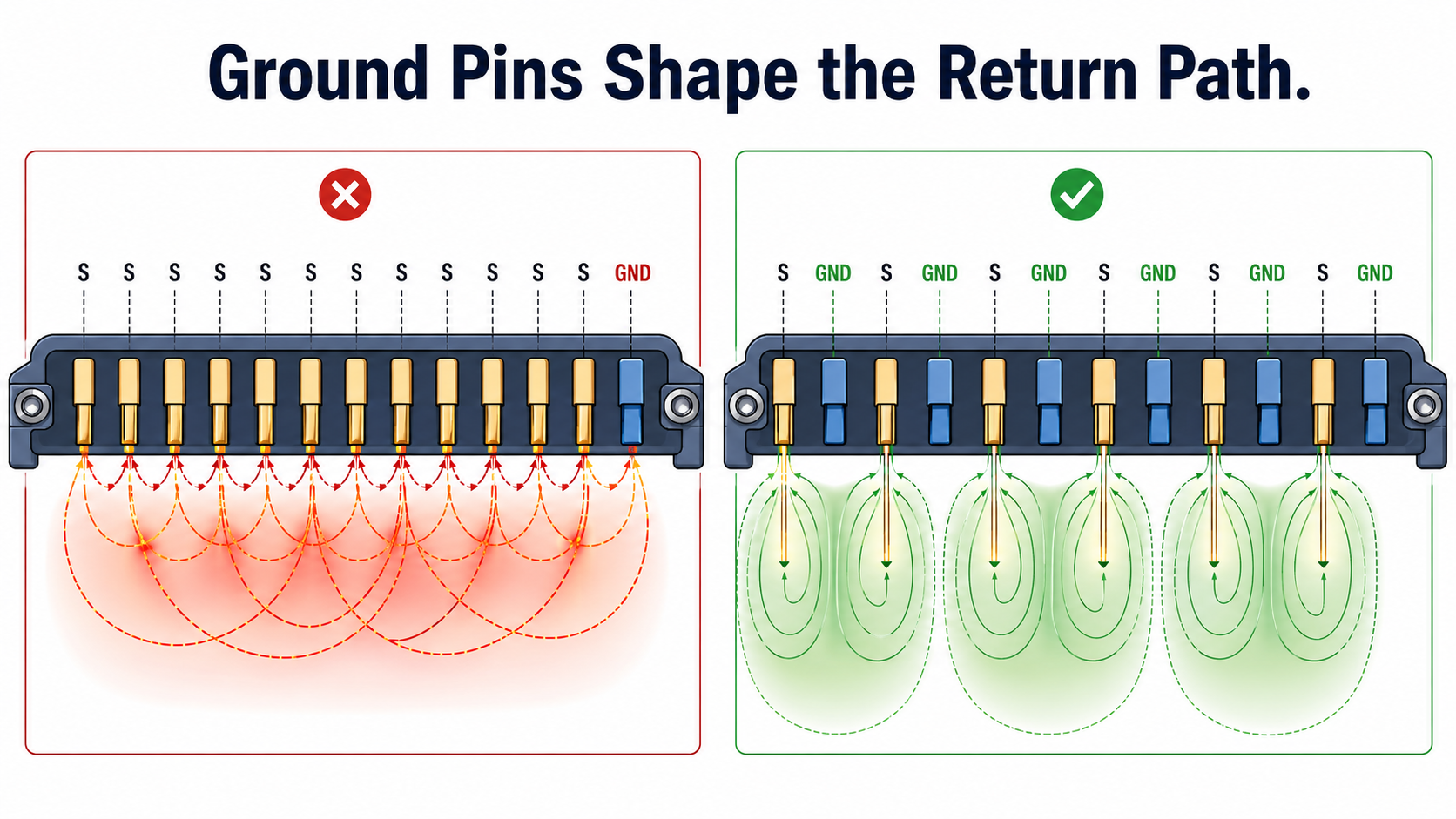
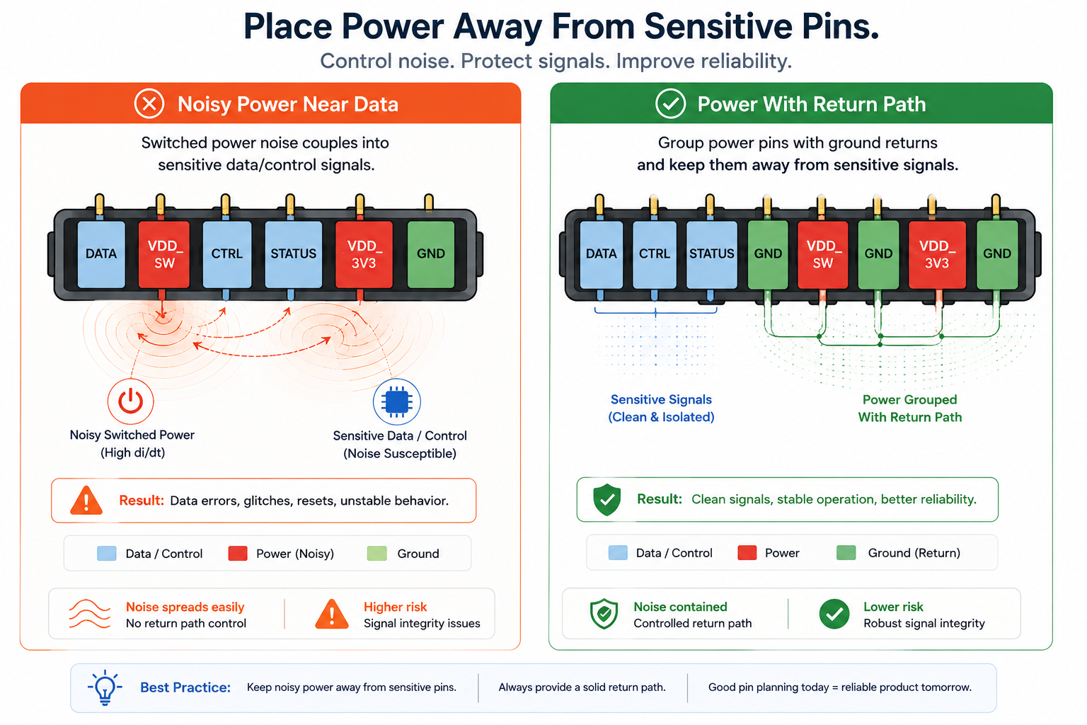
Ground Pins Are Not Filler
Ground pins are often the first thing sacrificed when the pin count gets tight.
That is usually a mistake.
In dense connectors, ground pins are not passive filler. They provide local return paths, reduce loop area, improve impedance consistency, and help contain coupling between neighbouring pins.
For high-speed interfaces, ground interleaving is one of the most effective crosstalk-control tools.
A simple pattern such as:
Signal – Ground – Signal
is far better than:
Signal – Signal – Signal – Ground
Especially when the signals are fast, unrelated, or travelling between boards through a cable or FPC.
The same concept applies to differential pairs. A pair should have a clean return environment around it. Placing a noisy single-ended control line immediately beside a high-speed pair can create intermittent behaviour that only appears under traffic.
At Hoomanely, ground placement is treated as an intentional part of connector design. If we cannot afford enough ground pins, that is not a routing inconvenience. It is a system-level warning that the connector may be undersized for the interface mix.
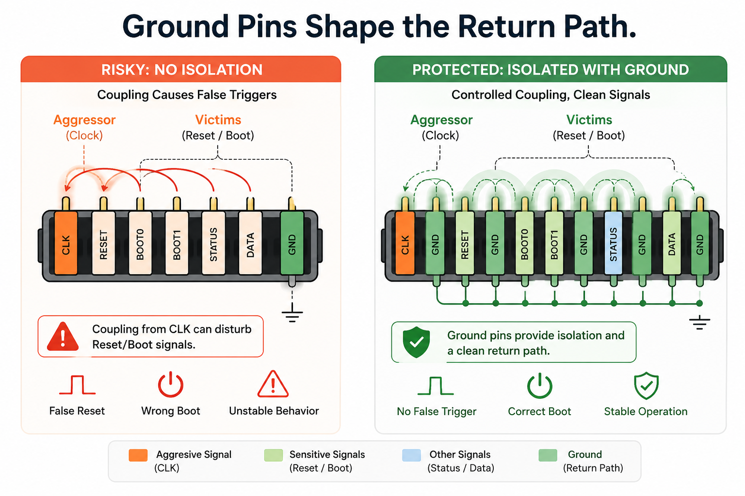
Separate Aggressors From Victims
Every dense connector has aggressors and victims.
Aggressors are the signals that inject noise into the connector environment. Victims are the signals that may misbehave when disturbed.
The mistake is assuming low-speed signals are always safe.
A reset line may change only once, but a coupled glitch can reboot the system. A boot-mode strap may be sampled only during startup, but if a nearby high-speed lane toggles during that sampling window, the board may enter the wrong mode. A presence-detect pin may be slow, but a false transition can trigger an incorrect module state.
A good connector pinout deliberately separates these categories.
For example:
- Do not place reset beside clocks.
- Do not place boot straps beside fast data lanes.
- Do not place analog references beside switching power.
- Do not place detect pins beside PWM or high-current enable signals.
- Do not place low-speed configuration buses in the middle of high-speed lanes unless protected by ground.
This is not about fear. It is about respecting edge energy.
A quiet signal does not stay quiet just because the schematic says it is low frequency.
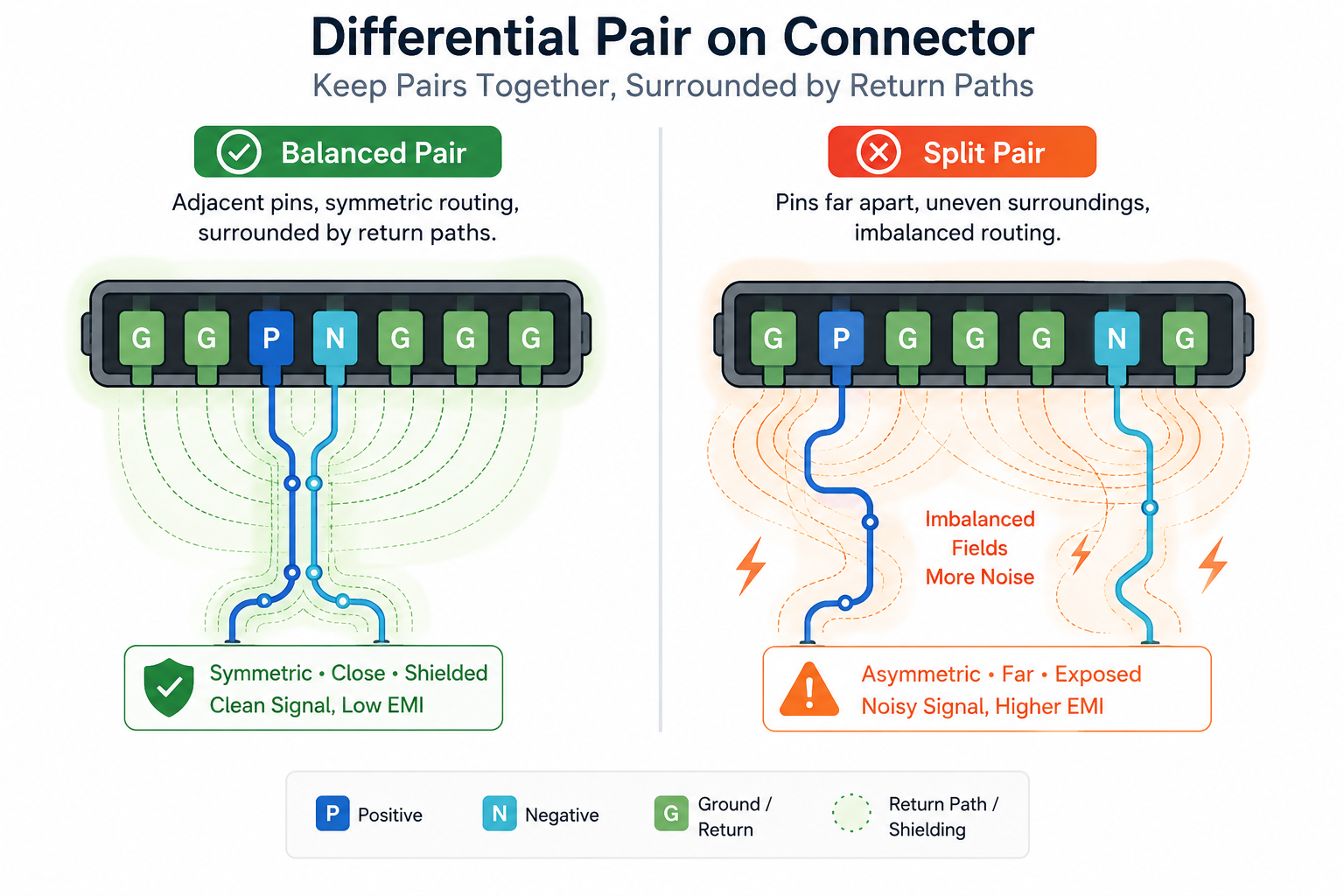
Differential Pairs Still Need Discipline
Differential signaling helps, but it does not excuse poor connector design.
A differential pair can reject common-mode noise, but only when the pair remains balanced. If one side sees a different nearby environment than the other, the pair becomes less symmetrical. That imbalance can convert coupled noise into differential error.
This is why connector pin assignment for differential pairs should maintain symmetry.
The two pins of a pair should stay adjacent, length-matched, and surrounded by a similar return environment. If possible, place grounds beside the pair or between unrelated pairs. Avoid splitting pairs across connector regions with different reference conditions.
A poor differential connector pinout may still pass short bench tests but fail under cable movement, temperature variation, or manufacturing spread.
That is the kind of failure we try to prevent through architecture rather than chase later with patches.
Power Pins Can Also Create Crosstalk Problems
Power pins are not automatically quiet.
A switched rail, LED supply, radio supply, or high-current sensor rail can inject noise into nearby connector pins. During startup or feature activation, these rails may carry fast current changes. If they sit beside sensitive data lines, they can disturb them capacitively or through shared return paths.
Power pin placement should therefore follow intent.
Stable supply pins can be grouped with nearby ground returns. Noisy or switched power should be separated from sensitive controls. High-current pins may require multiple pins, local grounds, and clear return paths to avoid forcing current through connector regions used by data.
In compact products, power and data often share the same connector. That is acceptable only when the pinout makes their relationship explicit.
A connector carrying both power and trust must be designed like it carries both power and trust.
Budgeting Means Choosing Limits Before Problems Appear
A crosstalk budget is not always a complex spreadsheet.
At the hardware architecture level, it is a set of design limits that guide decisions before layout begins.
For example:
- How many high-speed signals can sit together before a ground pin is required?
- Which signals are never allowed beside clocks?
- Which pins require ground adjacency?
- Which low-speed signals need filtering if placed near fast lanes?
- Which power pins must be isolated from sensor or reset signals?
- Which connector regions are reserved for quiet control and identity pins?
These rules do not need to be excessive. They need to be consistent.
Without a budget, every connector pinout becomes a negotiation. With a budget, the team has a standard.
That standard protects the product when pressure increases.
Because pinout decisions often happen under constraint: limited connector size, fixed mechanical envelope, available cable family, board outline limitations, or legacy compatibility. A crosstalk budget keeps those constraints from quietly damaging reliability.
The Cable or Mating Board Is Part of the Pinout
A connector does not exist alone.
The mating board, cable, FPC, harness, or flex path continues the electrical environment.
A pinout that looks reasonable on the PCB may become weaker through the cable if return paths are not preserved. For example, placing grounds near high-speed pins on the connector helps only if the cable or flex maintains that relationship through its length. If the mating cable rearranges or spreads signals poorly, the connector discipline is lost immediately.
This is why pinout review should include the complete path:
source device, PCB routing, connector pinout, cable or flex geometry, mating connector, receiving board layout, termination, and return path.
At Hoomanely, this complete-path thinking matters because modular boards often communicate through compact interconnects. The failure rarely belongs to only one board. It belongs to the interface as a system.
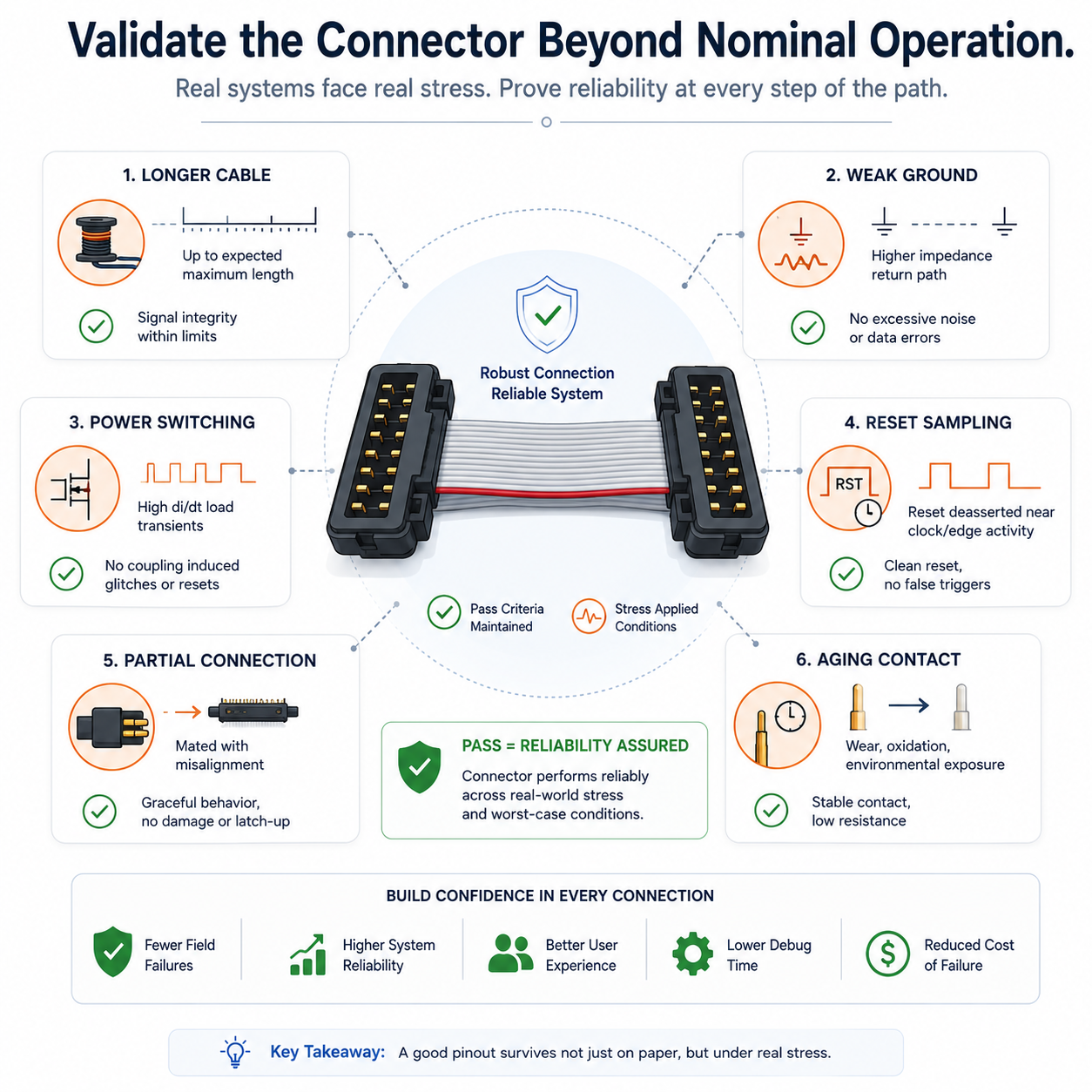
Test the Pinout Like a Failure Boundary
A good connector pinout should be reviewed not only for function, but for failure behavior.
We ask:
What happens if the cable is longer than expected?
What happens if the return connection is weak?
What happens during high-speed traffic and reset sampling?
What happens when power rails switch while data is active?
What happens if the mating board is partially connected?
What happens when the connector ages or contact resistance increases?
These questions expose weak pin assignments early.
A connector that passes nominal operation but fails under edge cases is not robust enough for product architecture. It may be acceptable for a prototype. It is not acceptable for a design standard.
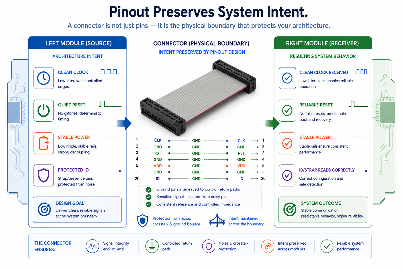
Hoomanely’s View: Pinouts Preserve Intent
A connector pinout is one of the few places where architecture becomes physical immediately.
The schematic may show clean blocks. The firmware may have clean ownership. The mechanical design may have a neat module boundary. But the connector decides whether those boundaries remain electrically true.
If high-speed signals are not given return paths, the boundary becomes noisy. If sensitive lines are placed beside aggressors, the boundary becomes fragile. If power pins are mixed carelessly with data pins, the boundary becomes unpredictable.
That is why we treat connector pinouts as design a worth reviewing carefully.
A good pinout tells the next engineer what the system values:
quiet resets, stable clocks, protected configuration, clean return paths, safe power, and predictable module behaviour.
A poor pinout only tells them that the signals fit.
Fitting is not enough.
Final Thoughts
Dense high-speed connectors are powerful because they let small products become modular, serviceable, and scalable.
But density creates responsibility.
The closer the pins, the more important the electrical relationships become. Every fast signal needs a return path. Every sensitive signal needs protection. Every power pin needs context. Every differential pair needs symmetry. Every connector needs a crosstalk budget before layout locks the design in place.
At Hoomanely, we do not see connector pinout as an administrative step.
We see it as a product-reliability decision.
A well-designed connector keeps modules understandable, interfaces quiet, and failures rare.
A careless connector makes the product depend on luck.
And luck is not an architecture standard.