
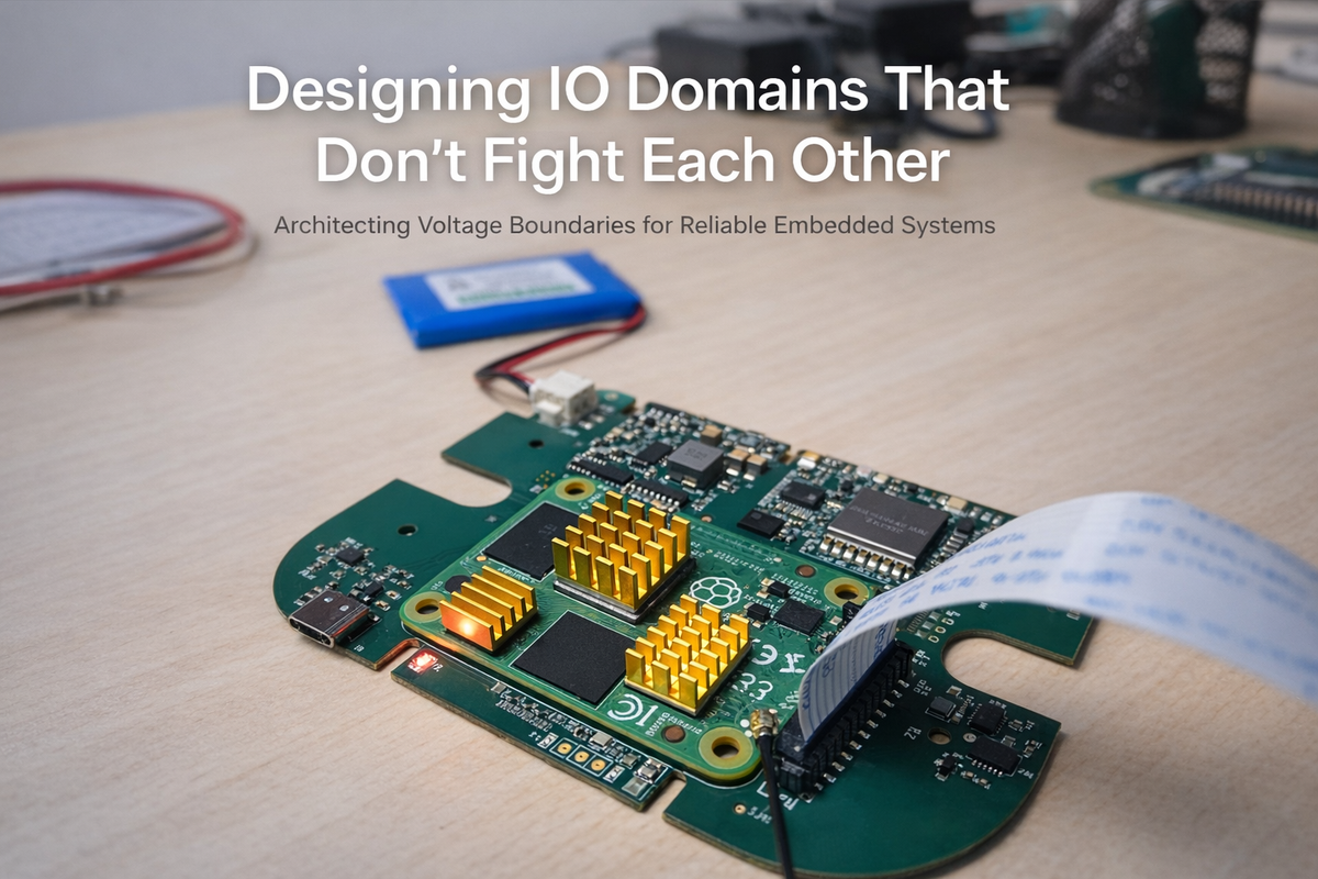
Designing IO Domains That Don’t Fight Each Other
In multi-voltage embedded systems, the most common instability doesn't come from firmware bugs. It comes from IO domains quietly fighting each other. Modern boards rarely operate on a single logic level. A typical sensor platform may include a 3.3V MCU domain, a 1.8V sensor IO domain, a 2.8V analogue sensor rail, open-drain buses, and high-speed digital interfaces.
If these domains aren't deliberately isolated and sequenced, they interact in subtle, damaging ways. The system may appear functional, until temperature shifts, brownouts occur, or startup timing changes slightly. At Hoomanely, we stopped treating IO voltage compatibility as a checkbox. We treat it as architecture. Because voltage domains aren't just electrical levels. They're behavioral boundaries.
The hidden problem: mixed-voltage assumptions
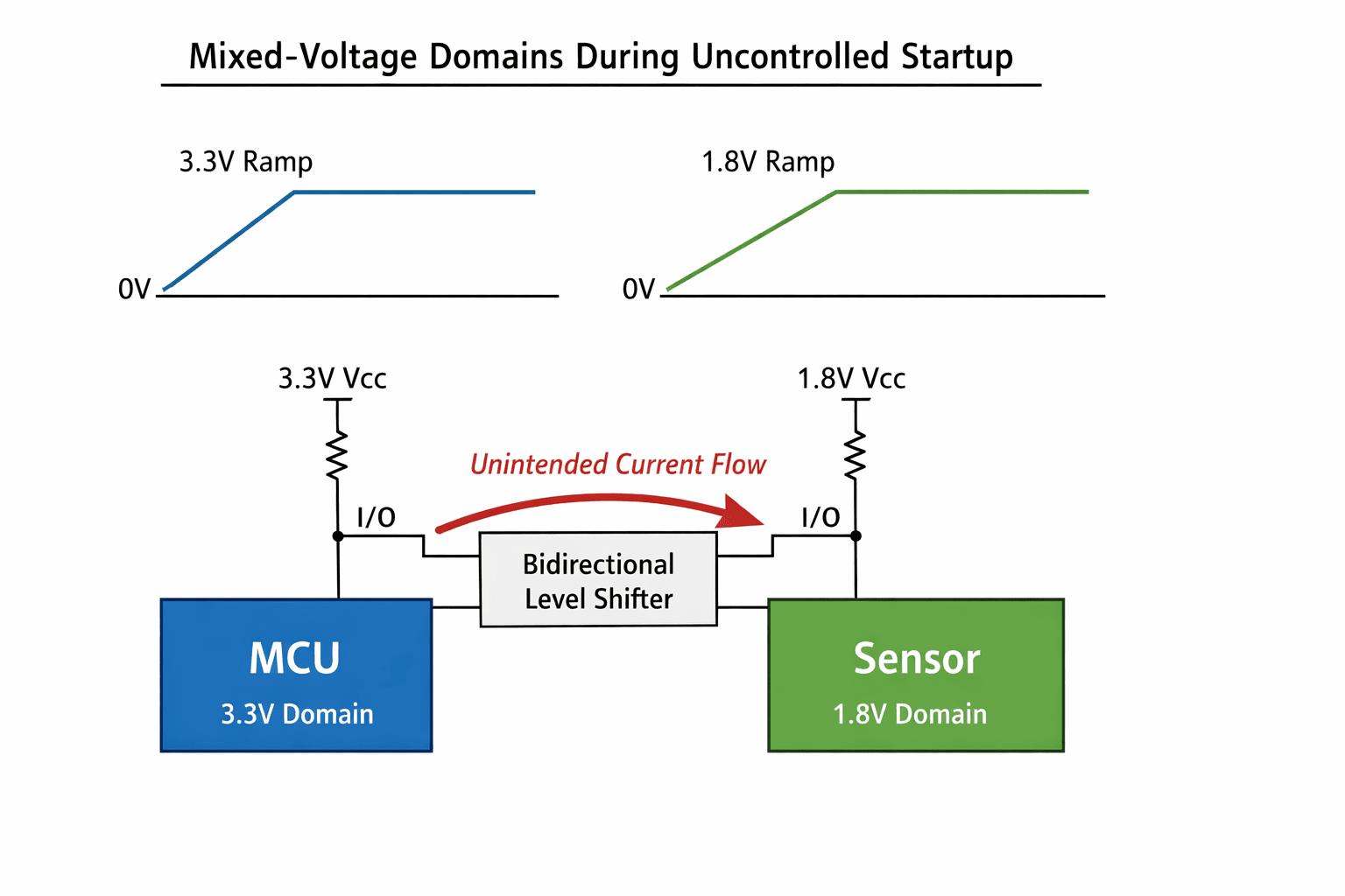
In many conventional designs, a level shifter is placed between 3.3V and 1.8V, pull-ups are added, the schematic passes review, and the board boots. But during real operation, IO pins power up at different times, pull-ups activate before rails stabilize, sensors partially bias through protection diodes, bidirectional buses experience injection currents, and edge rates differ across domains.
The issue is rarely visible in static design review. It emerges during transient states. And transient states define reliability.
IO injection: the silent silicon stress
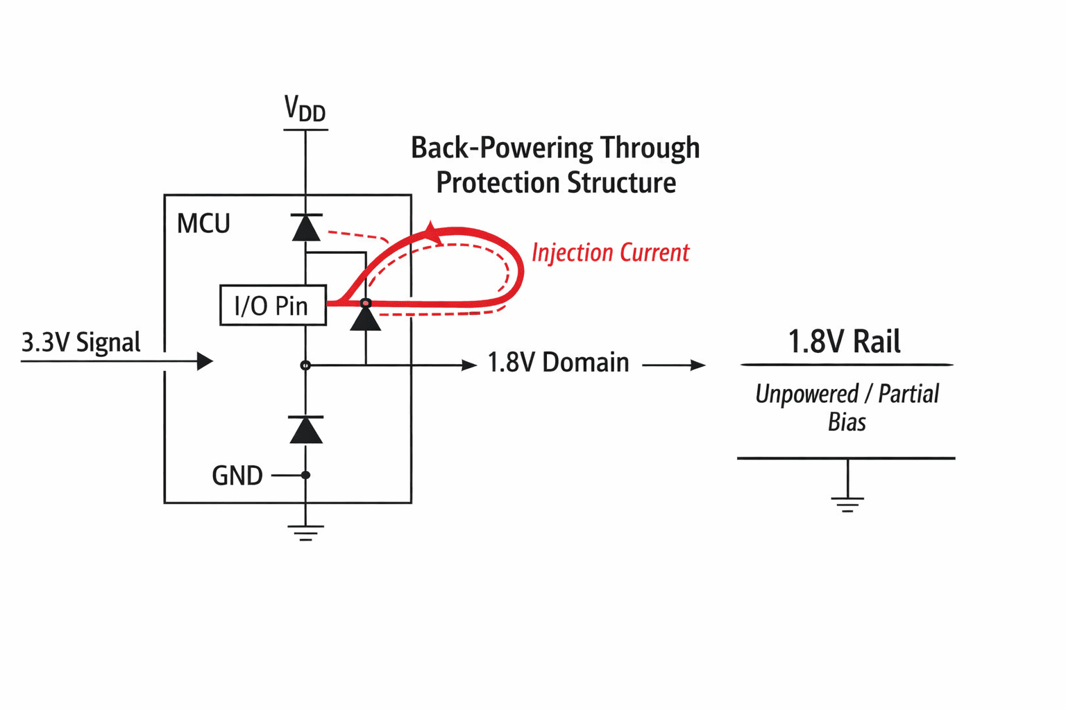
When a higher-voltage domain drives a signal into a lower-voltage domain that isn't yet powered, current flows through internal protection structures, causing back-powering of unpowered rails, partial biasing of analogue blocks, increased leakage current, long-term silicon stress, and in extreme cases latch-up. The system may still function, but the stress accumulates. We eliminated this by designing IO boundaries deliberately.
Level shifting is not enough
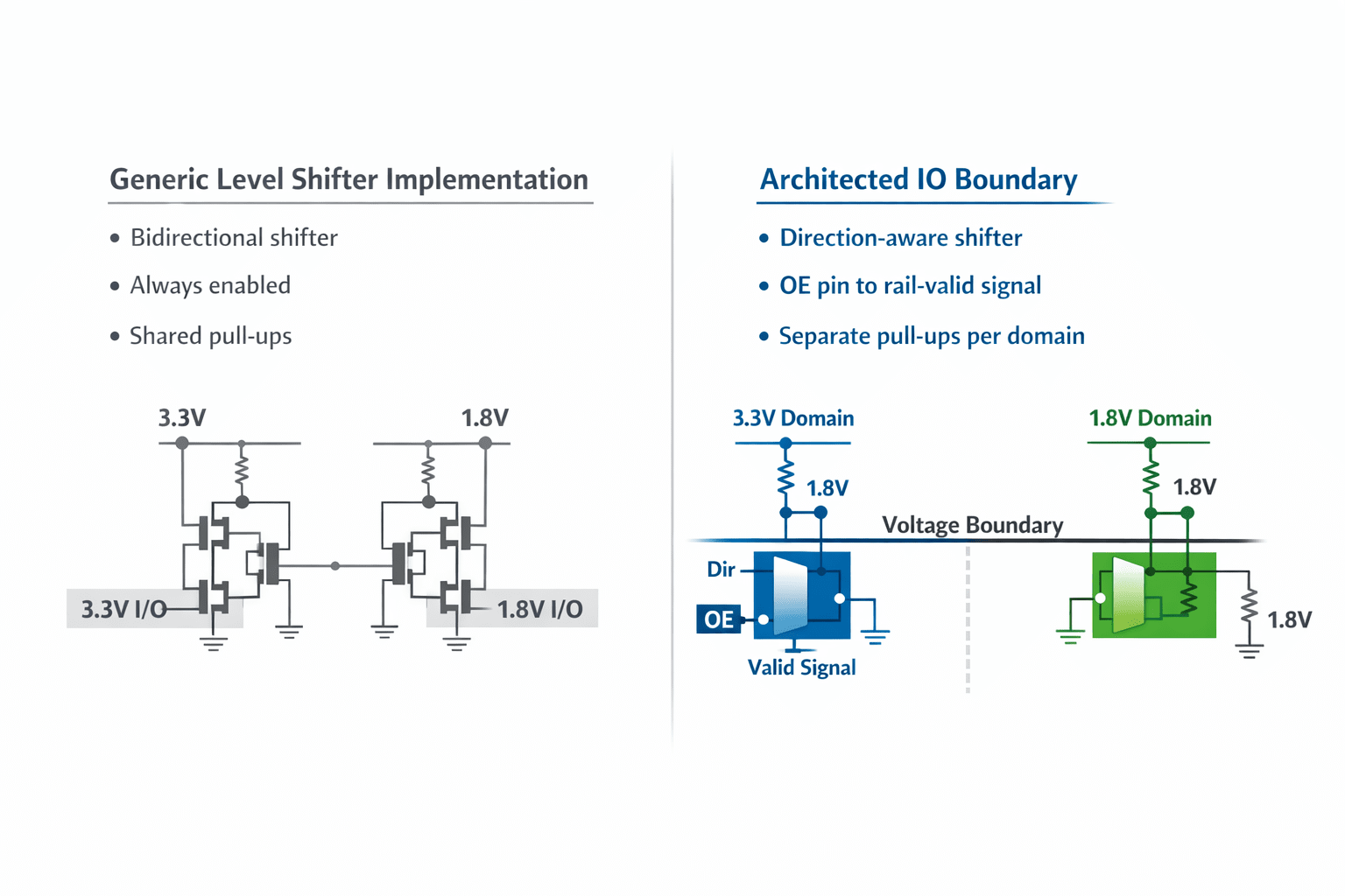
A level shifter alone doesn't guarantee isolation. Key considerations we implement:
- Direction-aware translators instead of passive bidirectional devices
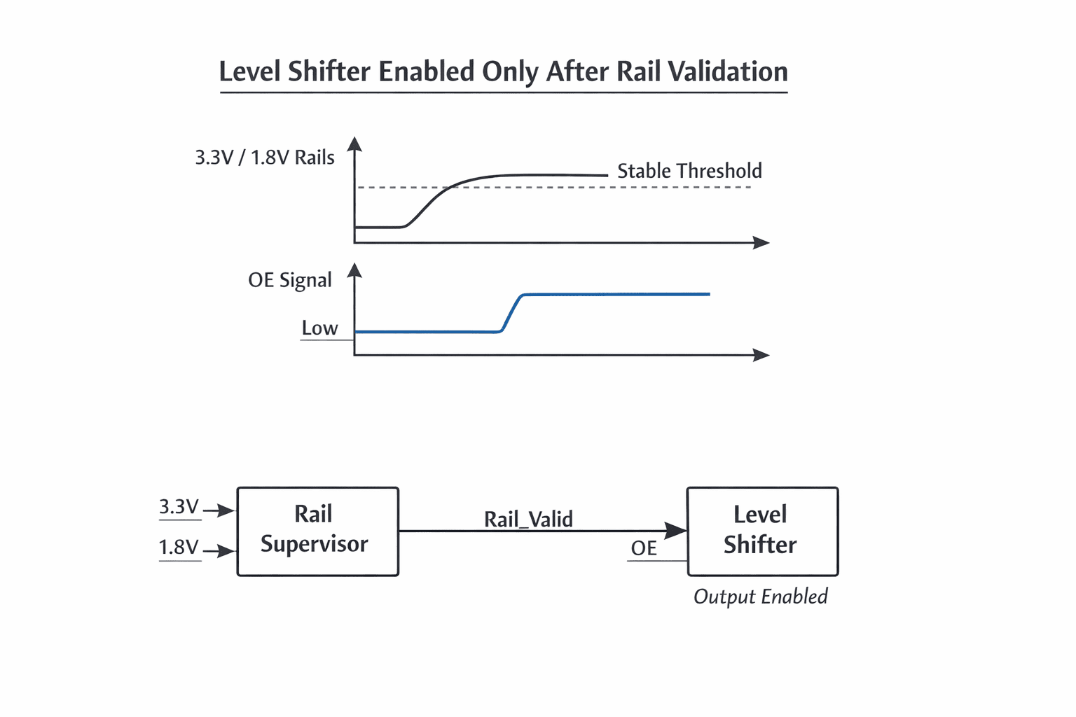
- OE (output enable) gating tied to rail validity
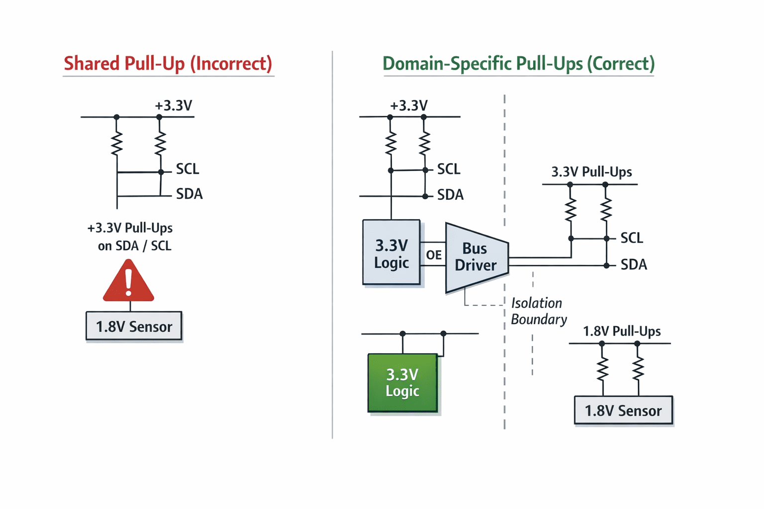
- Separate pull-ups per voltage domain
- Controlled edge rate where necessary
- Clear ownership of bus mastership
This transforms IO from "connected" to "architected.".
OE gating: enabling only when valid
We ensure level shifters are enabled only when both source and destination rails are stable, reset domains are in defined states, and downstream sensors aren't in partial bias conditions. This prevents phantom powering during ramp, bus contention during reset, and glitch propagation across domains. The IO path exists only when both domains are electrically valid.
Open-drain buses and pull-up discipline
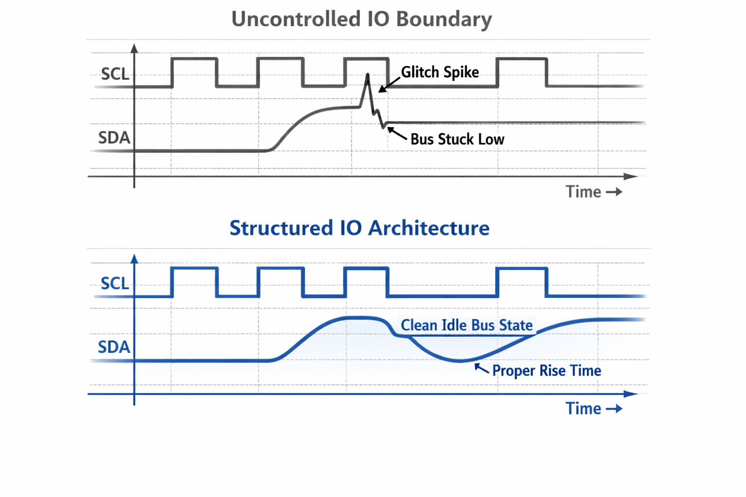
I2C buses are especially vulnerable. Common mistakes include shared pull-ups across domains, pull-ups connected to a rail that ramps slowly, and no consideration of rise-time versus voltage threshold. We implement domain-specific pull-ups, pull-up rails validated before release, clean routing to minimize parasitic capacitance, and explicit bus idle state validation during boot. This eliminates bus lockups that originate before firmware runs.
Physical layout reinforces logical isolation
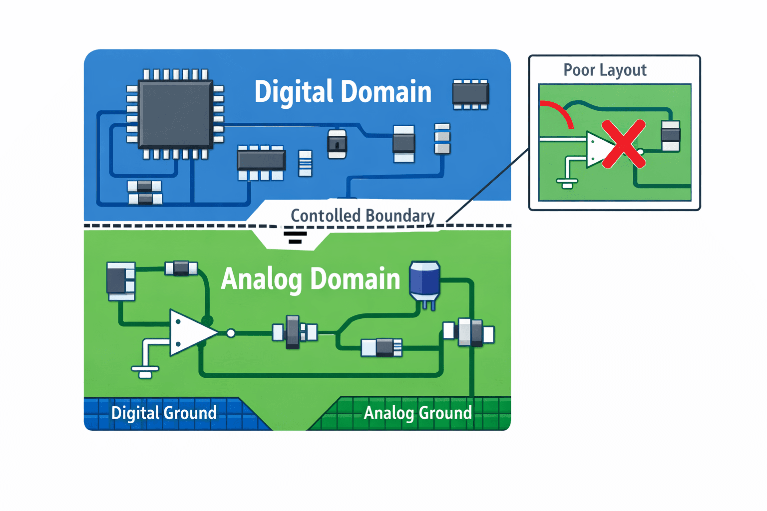
Voltage domain separation isn't only schematic-level. We reinforce isolation through clear analog versus digital ground strategy, dedicated return paths, minimal cross-domain trace coupling, and avoidance of shared high-speed and low-speed reference planes. Electrical behavior follows physical routing. A well-drawn schematic with poor layout is not isolation.
Practical improvements we observed
After restructuring IO domain architecture, we measured reduced startup bus errors, since I2C and sensor initialization failures during cold boot were eliminated. Lower leakage during partial power, since back-power injection currents were removed. More predictable brownout recovery, since when rails dip momentarily, domains return cleanly without undefined latch states. Cleaner signal integrity, since edge rates stabilized due to proper domain separation. And reduced long-term stress on MCU pins, with no more repeated injection through protection diodes during ramp cycles. These improvements don't show up in a feature list. They show up in durability.
Conventional IO design vs structured IO architecture
The conventional approach adds a generic level shifter, connects pull-ups, assumes compatibility, and handles glitches in firmware. The Hoomanely approach defines domain boundaries clearly, gates level shifters with rail validity, separates pull-ups by voltage domain, controls IO enable timing, validates startup transitions with scope measurement, and ensures no IO path exists during partial rail states. The difference is architectural intent.
Designing for brownout and recovery
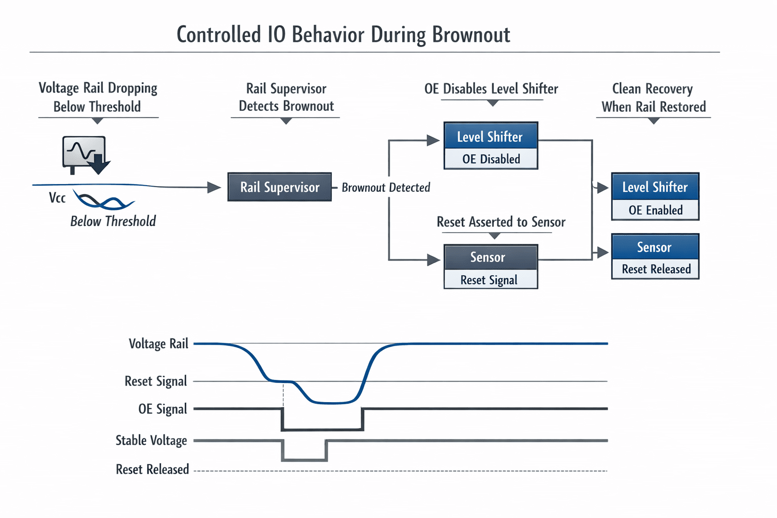
Voltage dips are inevitable in real systems. If IO domains aren't properly isolated, one domain collapses faster than another, protection structures conduct unexpectedly, buses freeze, and sensors remain in undefined states. We ensure rail supervisors enforce reset before unsafe voltage thresholds, level shifters disable automatically during rail collapse, IO lines return to known bias states, and the recovery path is deterministic. The system doesn't depend on firmware to clean up electrical instability.
Why this matters more in sensor systems
Sensor-heavy platforms combine analog bias circuits, high-speed digital lanes, precision timing blocks, and mixed-voltage logic. An unstable IO boundary can distort sensor readings, introduce timing jitter, trigger spurious interrupts, and corrupt initialization sequences. Stability at the voltage boundary preserves integrity at the data layer.
The core principle
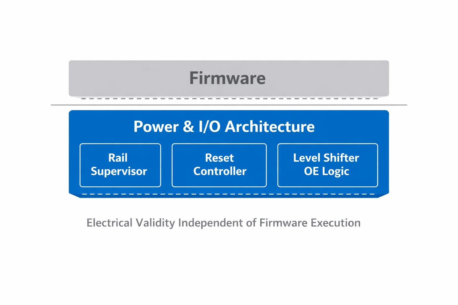
An IO connection should only exist when both sides are electrically valid. If one side is unstable, the boundary must be closed. That principle drives OE gating, reset alignment, rail sequencing, pull-up control, and brownout management. We don't rely on firmware to correct hardware ambiguity. We prevent ambiguity.
Designing IO before writing code
Our methodology enforces clear voltage domain documentation, defined rail dependencies, IO ownership mapping, startup and shutdown timing validation, and scope-based verification of ramp and release order. If firmware crashes during boot, IO must remain safe. If a sensor resets mid-operation, IO must not corrupt adjacent domains. Electrical integrity precedes software logic.
Final thought
Voltage domains are invisible in user-facing features. But they define startup reliability, long-term silicon health, brownout behavior, signal integrity, sensor accuracy, and product lifespan. Designing IO domains that don't fight each other isn't about compliance. It's about respect for electrical boundaries. And in embedded systems, respecting boundaries is the difference between a product that "works most of the time" and one that works every time.



