Keeping Data Interfaces Stable While Power Is Negotiating
Timing discipline during voltage transitions
Power does not become stable in one instant.
A board may receive input power, but the internal rails are still ramping. A regulator may be enabled, but its output has not yet reached tolerance. A level shifter may see one side alive before the other. A processor may start toggling pins while a peripheral is still held in reset. A communication transceiver may be electrically connected before its local supply is valid.
During this window, data interfaces are vulnerable.
The system is not fully off.
It is not fully on.
It is somewhere in between.
That in-between state is where many intermittent embedded failures begin.
At Hoomanely, this problem shows up frequently in modular, multi-domain hardware. A sensor board may wake before the main processor. A carrier board may apply power before firmware is ready. A camera interface may see voltage on one side while the other side is still ramping. A CAN transceiver, level translator, sensor bus, or high-speed interface may become electrically present before it should be allowed to communicate.
The mistake is assuming that once power negotiation begins, data communication can also begin.
It should not.
Power negotiation and data communication need a disciplined handoff.
Until the voltage environment is valid, interfaces should remain quiet, isolated, or explicitly held in safe states.
Voltage Transition Is Not a Communication State
A common design weakness is allowing data lines to behave normally during voltage movement.
The input supply rises.
A regulator starts.
A peripheral receives partial voltage.
The MCU boots.
GPIOs wake in whatever state the silicon default provides.
If an interface is connected during this phase, it may begin producing signals before either side is ready.
This is especially dangerous because digital signals look deceptively simple. A logic high is a logic high only when both devices agree on supply voltage, threshold, reference ground, and valid operating range.
During voltage transition, those assumptions may not hold.
A 1.8 V signal may reach a device whose IO rail is not yet valid. A 3.3 V pull-up may bias a line connected to an unpowered sensor. A UART line may look like a start bit while the receiver is still crossing its threshold region. An I2C pull-up may keep a partially powered device alive through its IO structure.
The interface may not be communicating in any meaningful sense, but electrically, it is already active enough to cause trouble.
The first discipline is simple:
Voltage transition should be treated as a no-communication state.
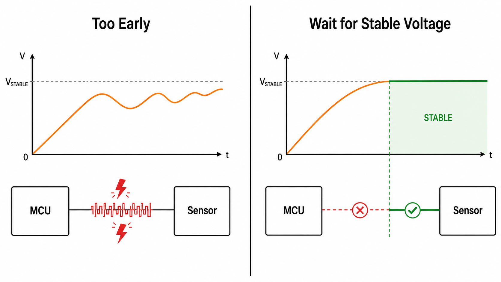
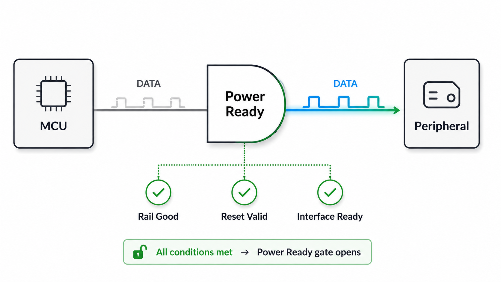
Stable Power Must Own the Right to Communicate
A data interface should not become active just because two pins are connected.
It should become active only after the system confirms that the electrical environment is valid.
That usually means:
- the relevant rails are within tolerance,
- the reset state is defined,
- both sides of the interface are powered,
- level shifters are enabled intentionally,
- pull-ups are tied to the correct domain,
- bus owners are known,
- and the firmware has configured the pins.
Until these conditions are true, the interface should remain inactive.
This is not about making the design slow. It is about giving communication the proper authority.
In a Hoomanely's vBus architecture, power readiness and interface readiness are separate milestones. A rail becoming valid does not automatically mean a bus may start. A peripheral leaving reset does not automatically mean it may drive lines. A connector receiving power does not automatically mean traffic is allowed.
Communication is a privilege that begins after electrical readiness, not during it.
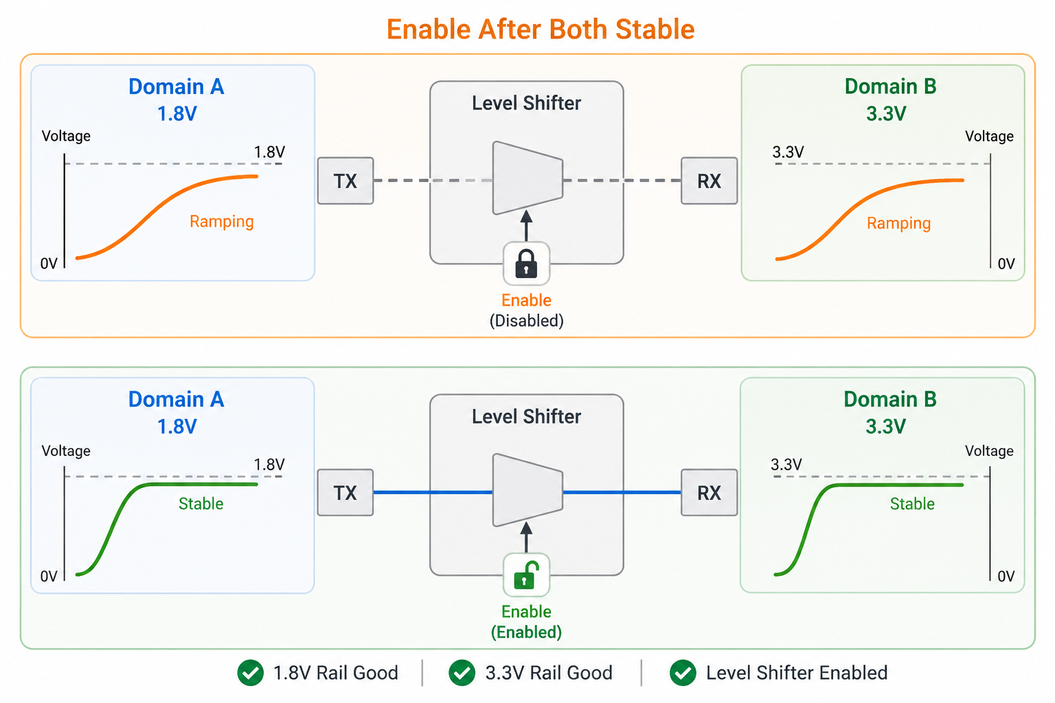
Level Shifters Need Timing Discipline
Level shifters are often added to solve voltage mismatch, but they can create problems if their enable timing is not controlled.
Many systems include 1.8 V logic on one side and 3.3 V or 2.8 V logic on the other. During power-up, one rail may arrive earlier than the other. If the translator becomes active too early, it can pass undefined states, leak current, or back-power one domain from another.
This is especially true for automatic bidirectional level translators. They can be convenient during normal operation but less predictable during partial-power conditions.
A safer design gives the translator a defined enable policy.
The translator should stay disabled until both voltage domains are stable. Its output enable should have a safe default state. The signals passing through it should not be trusted until the related power-good conditions are satisfied.
In practice, this means the OE pin of the translator is not just a convenience. It is part of the power sequencing architecture.
If OE floats, the interface is uncontrolled.
If OE is tied directly high, the interface may become active before the domains are ready.
If OE is held inactive until both domains are valid, the interface behaves like a controlled boundary.
That boundary is what keeps data lines quiet while power is still negotiating.
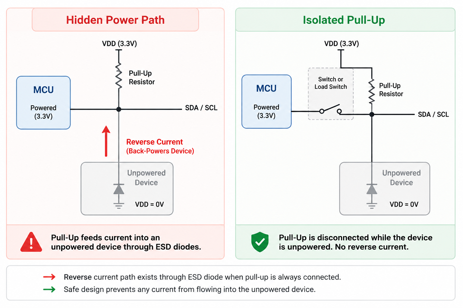
Pull-Ups Can Accidentally Become Power Paths
Pull resistors are not just logic-state helpers. During voltage transitions, they can become unintended power sources.
For example, an I2C bus may use pull-ups to a 3.3 V rail while a connected 1.8 V device is still unpowered. Current may flow through the device’s IO protection structures. The device is not properly powered, but it is no longer fully off either.
That partial condition can cause unpredictable behaviour.
The device may hold the bus low.
It may consume unexpected current.
It may fail to reset cleanly.
It may wake into an invalid state.
This is why pull-up placement matters.
A bus pull-up should be tied to the domain that truly owns the bus during that phase. If multiple voltage domains share a bus, the pull network should not accidentally power the wrong side. In some cases, switched pull-ups, bus switches, or level-shifter-controlled isolation are cleaner than permanent pulls.
The question to ask is not only:
“Does this pull resistor create the right idle level?”
The better question is:
“Where does this pull resistor source current when another domain is off?”
That question catches many hidden boot and shutdown problems.
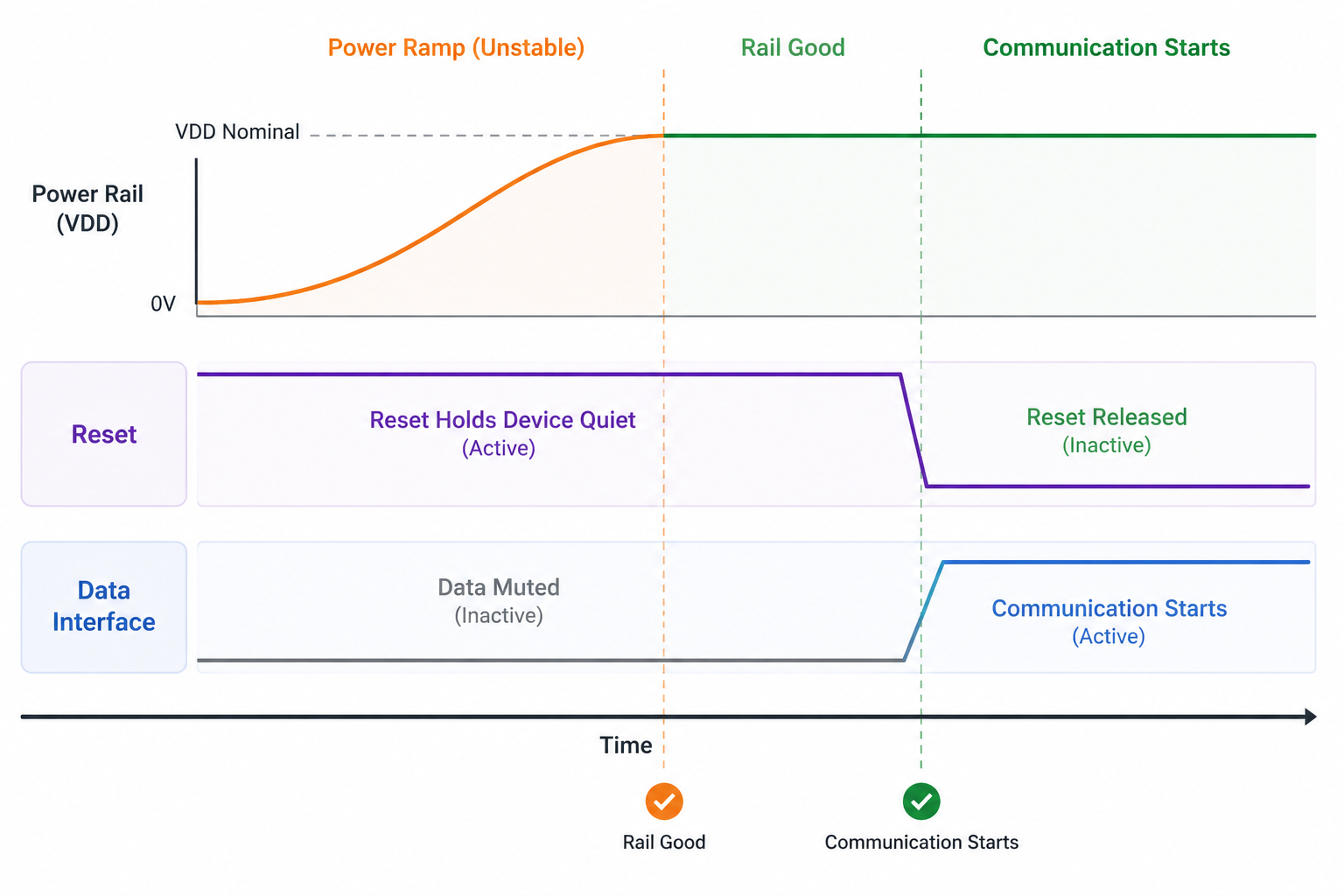
Reset Should Beat Communication
Reset timing is one of the simplest ways to keep interfaces stable.
A peripheral should not drive a bus while it is still in a power-transition zone. Holding that peripheral in reset until its rail is stable prevents many false transactions and bus conflicts.
But reset is only effective when it is properly referenced to the same electrical reality as the device being controlled.
If reset releases too early, the device may wake before the interface is safe. If reset is driven from a different power domain, it may back-power or mis-bias the device. If reset floats while the MCU is booting, it may release unpredictably.
Good reset design is not only about asserting reset at startup.
It is about ensuring that reset remains valid while voltage is invalid.
In practical terms:
- reset should have a safe default,
- reset should be supervisor-controlled when needed,
- reset should not depend only on firmware,
- reset should release after rail-good, not merely after delay,
- and reset should align with interface enable timing.
A clean interface starts with a quiet peripheral.
A quiet peripheral usually starts with disciplined reset.
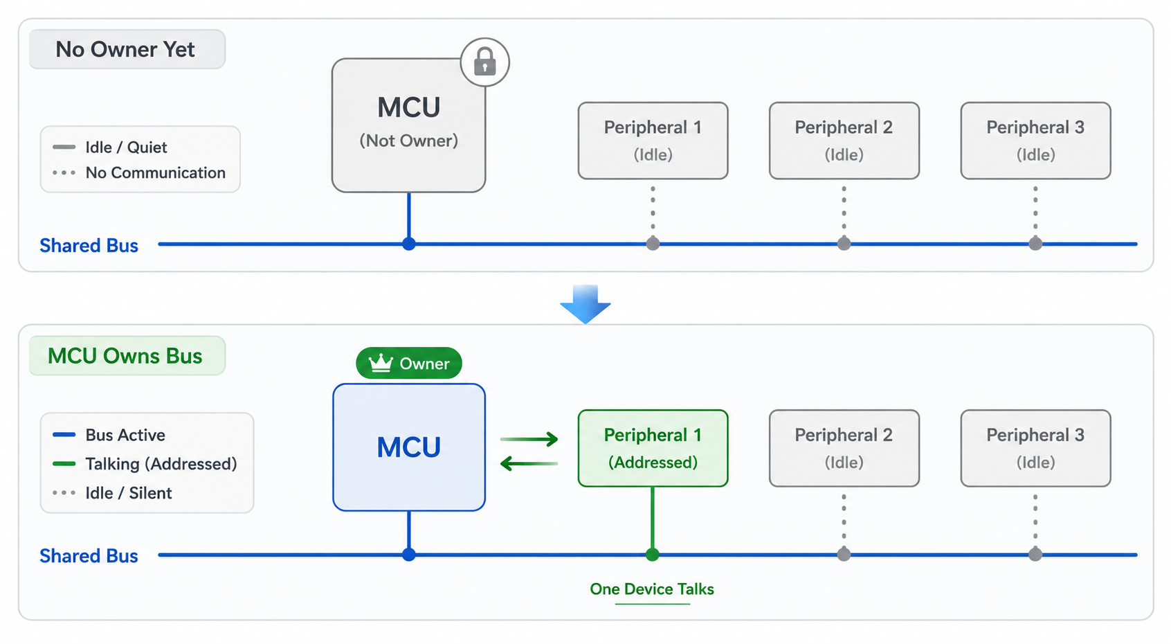
Bus Ownership Must Be Delayed Until Rails Are Valid
Many data interfaces fail during startup because ownership is unclear.
An MCU may wake and configure pins while the peripheral side is still powering. A sensor may pull an interrupt line before the host is ready. A transceiver may drive a bus before standby control is valid. A secondary processor may attempt communication before the main system has completed negotiation.
The result is not always immediate failure. More often, it becomes intermittent behaviour:
- first boot fails, second boot works,
- bus scan sometimes misses a device,
- UART receives garbage characters,
- I2C starts with SDA held low,
- SPI peripheral latches a false command,
- or CAN enters an unexpected bus state.
The fix is not simply adding more delays.
The fix is assigning ownership based on readiness.
The controller should not start a transaction until the physical bus is idle and the connected domain is valid. Peripherals should not assert interrupts until the host is ready to receive them. Transceivers should remain in standby until the controller enables them intentionally.
Ownership should be granted after voltage negotiation, not during it.
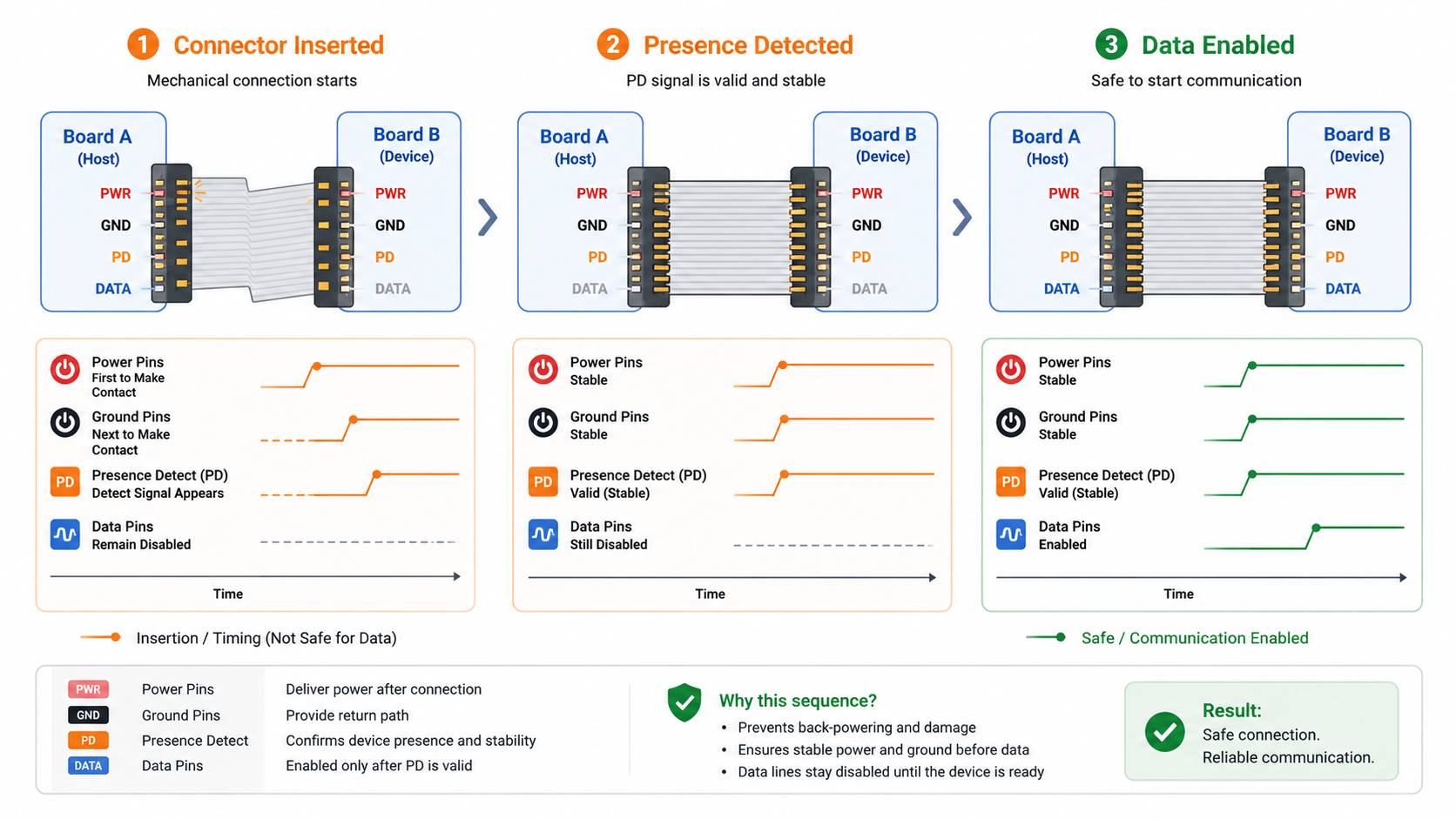
Connectors Make Timing More Complicated
Connectors introduce real-world timing uncertainty.
A cable or module may be attached while one side is powered. Ground may mate slightly before or after signal pins. Power may arrive through one path while data lines make contact through another. A ribbon cable may flex during insertion and briefly connect/disconnect signals.
Even if the product is not designed as hot-swappable, manufacturing and servicing often create hot-plug-like situations.
This means every connector that carries both power and data should be reviewed as a timing boundary.
Important questions include:
- What happens if data pins connect before power?
- What happens if power appears before ground is solid?
- What happens if the far-end board is unpowered?
- What happens if only one side of a level shifter is alive?
- What happens if the connector is partially inserted?
The goal is not to make every interface fully hot-swappable. That may not be necessary.
The goal is to prevent an ordinary assembly or service variation from creating a dangerous electrical state.
Sometimes this requires only simple changes: series resistors, enable gating, connector presence detection, better pull placement, or ensuring the bus stays idle until a presence signal is valid.
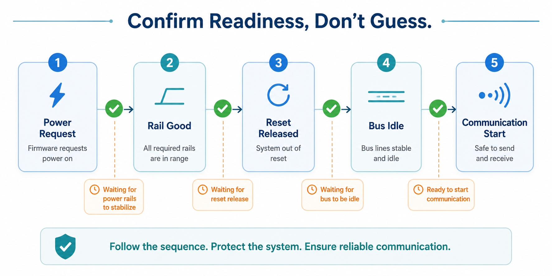
Firmware Should Confirm, Not Guess
Firmware often compensates for unstable voltage transitions with delays and retries.
Some delays are necessary. But if firmware is guessing how long hardware needs, the system remains fragile.
A better approach is for firmware to confirm readiness.
Before enabling communication, firmware should check what the hardware can expose:
- rail-good signals,
- power-sequence status,
- reset-complete status,
- presence detect,
- interrupt idle state,
- bus idle state,
- and peripheral acknowledgement.
This does not mean firmware becomes complicated. It means firmware stops pretending voltage transitions are invisible.
A disciplined firmware bring-up flow may look like this:
Power request issued.
Rail-good confirmed.
Reset held.
Interface isolation released.
Peripheral reset released.
Bus idle verified.
Communication begins.
The system feels more predictable because each step depends on a real condition rather than a hope that enough time has passed.
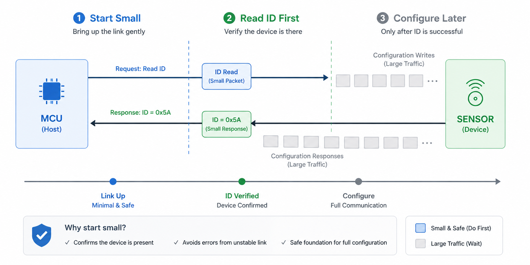
Keep Early Boot Traffic Minimal
Even after rails become valid, the first communication should be modest.
Do not start with the heaviest transaction.
A sensor bus scan, camera configuration burst, storage write, wireless negotiation, and debug log stream should not all begin at once. This creates both power and timing stress immediately after voltage negotiation.
The first interface activity should be low-risk.
Read an ID register.
Confirm presence.
Check status.
Then proceed to configuration.
This staged approach helps catch incomplete readiness without causing larger failures.
If the ID read fails, the system can retry, keep the peripheral isolated, or mark the feature unavailable. If a large burst transaction fails, the failure may leave the peripheral in a much less recoverable state.
Quiet startup is not only about keeping lines still.
It is also about starting communication gently.
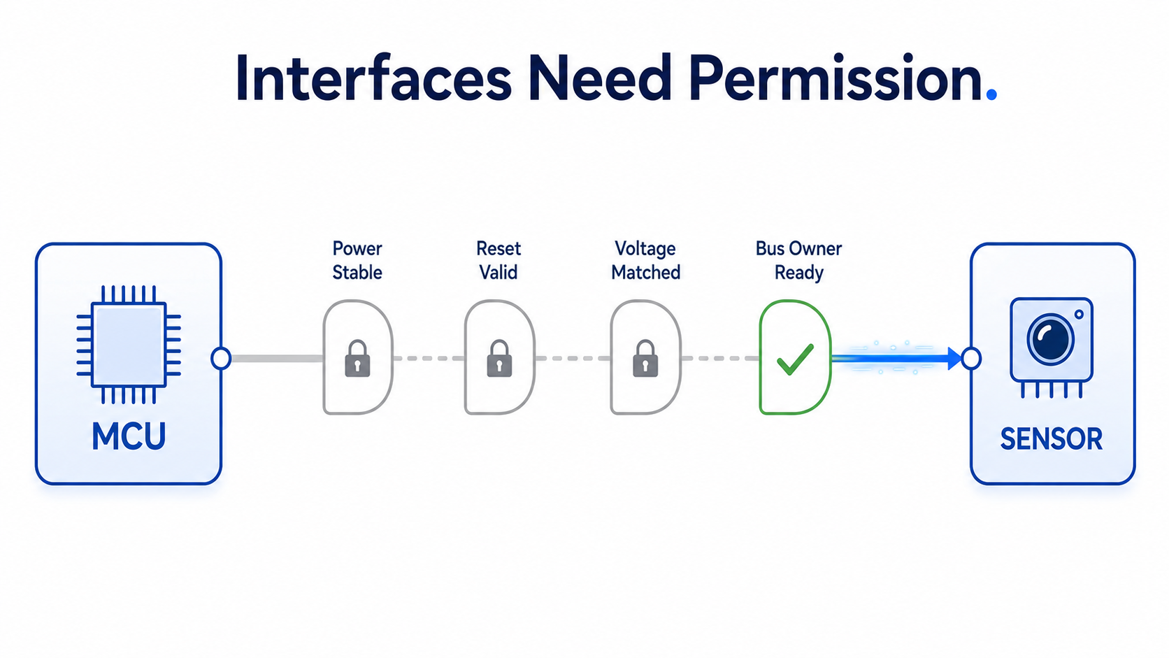
Hoomanely’s View: Interfaces Need Permission, Not Just Pins
At Hoomanely, we think of data interfaces as controlled relationships between power domains.
A bus is not just a group of traces.
It is a contract between two or more subsystems that says: both sides are powered, both sides agree on voltage, reset state is valid, ownership is known, and communication is now allowed.
This perspective is especially important in modular sensing platforms where power rails, connectors, level translators, sensors, and host processors may all wake at different moments.
The hardware should make invalid communication difficult.
The firmware should make valid communication intentional.
That combination is what prevents random startup issues from becoming recurring engineering distractions.
Final Thoughts
Data interfaces are most vulnerable while power is still negotiating.
During voltage transitions, logic thresholds move, rails ramp at different speeds, devices enter partial states, pull-ups can become power paths, and level shifters can unintentionally connect domains that are not ready to talk.
Reliable systems do not let communication begin just because power has started moving.
They wait for electrical reality to become valid.
That requires timing discipline: controlled resets, gated level shifters, safe pull placement, delayed bus ownership, connector-aware design, firmware readiness checks, and gentle first transactions.
The goal is not to slow the product down.
The goal is to prevent the system from talking before it understands its own electrical state.
Because in embedded hardware, stable communication begins before the first byte.
It begins with knowing when not to communicate.