
Making Sensor Power-Up Order Enforceable in Hardware
In embedded sensor systems, the difference between a stable product and a fragile one often comes down to something users never see: the order in which sensors wake up. It may sound like a small detail. But in multi-sensor platforms, where image sensors, proximity sensors, microcontrollers, and communication interfaces all share power domains and buses, startup order determines whether the system behaves predictably.
If the sequence is wrong, the result is rarely a catastrophic failure. Instead, it becomes something far worse: intermittent instability. A sensor that fails once every few hundred boots. An I2C bus that occasionally hangs during startup. A camera that initializes correctly most of the time, but not always. Those issues aren't software bugs. They're sequencing problems.
At Hoomanely, we stopped treating sensor startup order as a firmware responsibility. Instead, we enforce it directly in hardware, so the system behaves correctly even before firmware runs.
Why sensor power-up order matters
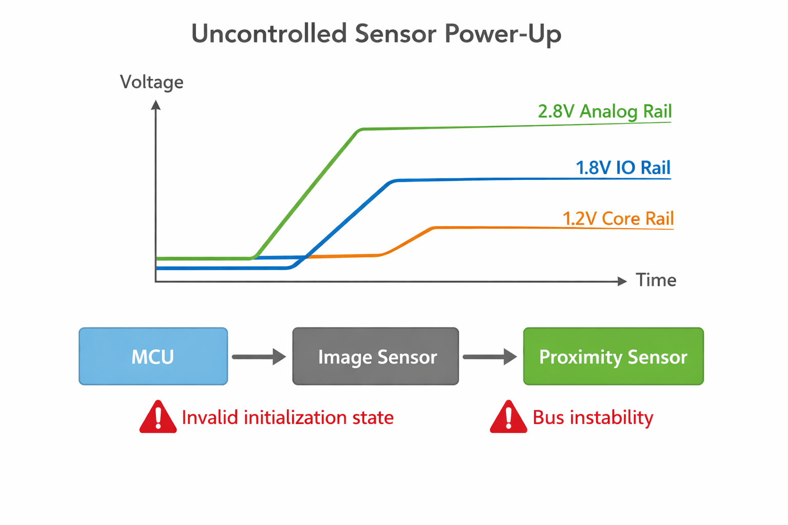
Most sensors aren't purely digital devices. Internally, they contain analogue bias generators, clock generators, internal state machines, calibration memory, and mixed-signal interfaces. These subsystems assume a defined power-up sequence. An image sensor typically requires analog rail stabilization, then IO rail stabilization, then core logic rail activation, then clock availability, then reset release.
If those events occur out of order, the sensor may latch an invalid internal state, enter a diagnostic mode, fail to respond on the bus, or generate unstable output. The problem is that many systems leave these dependencies to chance.
The common approach: let firmware handle it
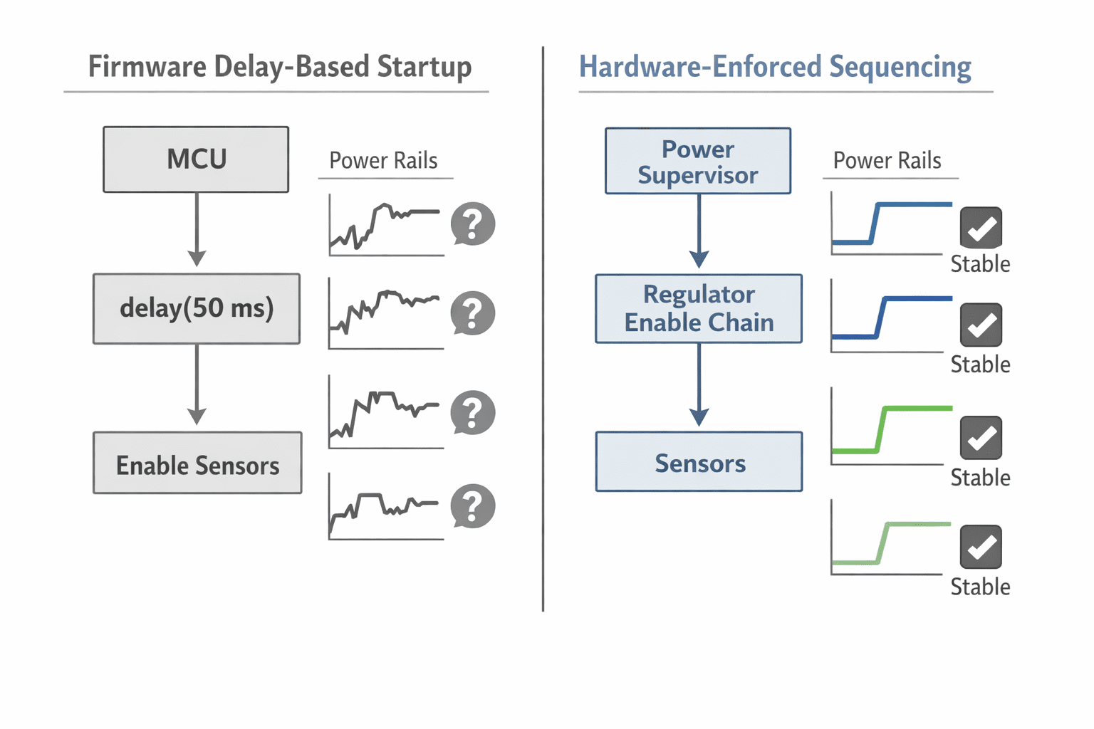
In many designs, the sensor startup flow looks like this: power rails enable together, the MCU boots, firmware delays for a few milliseconds, then sensors are initialized sequentially. This works under ideal conditions, but it assumes several things that aren't guaranteed, that rails reach stable voltage at the same rate, that sensors complete internal power-on reset within expected time, that bus lines remain stable during the ramp, and that IO pins don't inject current into partially powered domains.
In practice, these assumptions are fragile. Even small changes in temperature, power supply ramp rate, or component tolerance can alter startup timing enough to trigger intermittent behavior.
Hardware sequencing removes guesswork
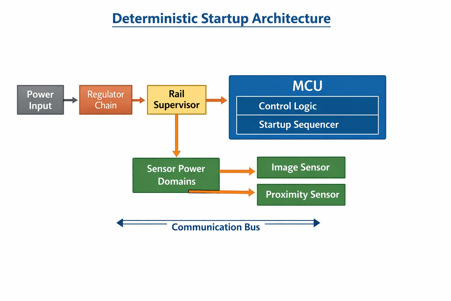
Instead of relying on firmware delays, we design the system so sensor power-up order is physically enforced. This means each stage of the system must reach a valid electrical state before the next stage is allowed to start. Typical enforcement mechanisms include regulator enable chaining, power supervisors, reset gating, and sensor shutdown pins. Each element ensures the next subsystem cannot start prematurely, so the sequence becomes deterministic.
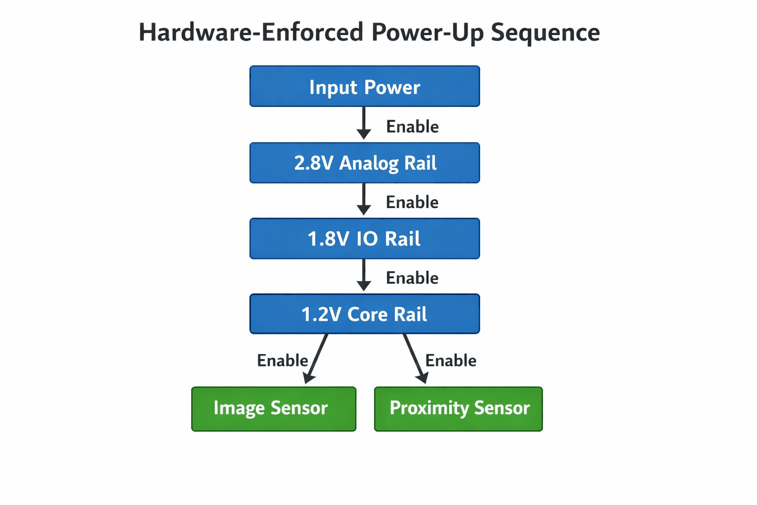
Using shutdown pins as hardware control points
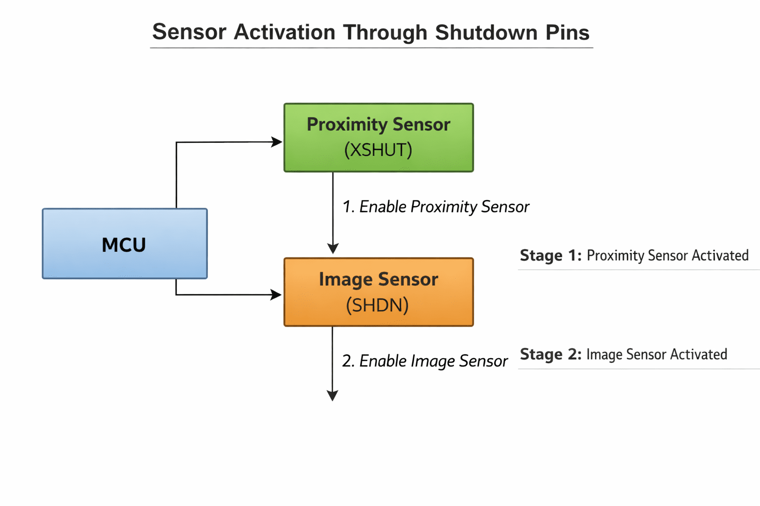
Many sensors include a shutdown or enable pin, often treated as a simple GPIO controlled by firmware. Instead, we use it as a hardware sequencing element. Power rails stabilize, the MCU completes basic initialization, firmware configures clocks and buses, and sensor shutdown pins are released in a defined order. The important detail is that these pins remain inactive until the hardware power tree is already stable. This ensures sensors never attempt to initialize in a partially powered system.
Separating power domains for sensors
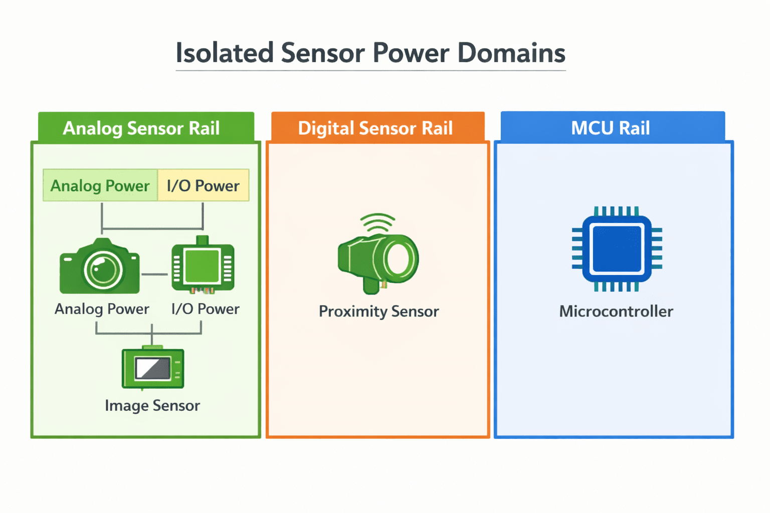
Another key technique is isolating sensor power domains. Instead of sharing the same rail across multiple sensors, we create controlled domain boundaries, letting individual sensors be enabled sequentially, preventing faulty devices from disturbing other sensors, and keeping analogue rails clean during digital ramp events. For example, an image sensor may have analog, IO, and core rails while proximity sensors share a separate controlled rail. This separation allows us to bring up devices one stage at a time.
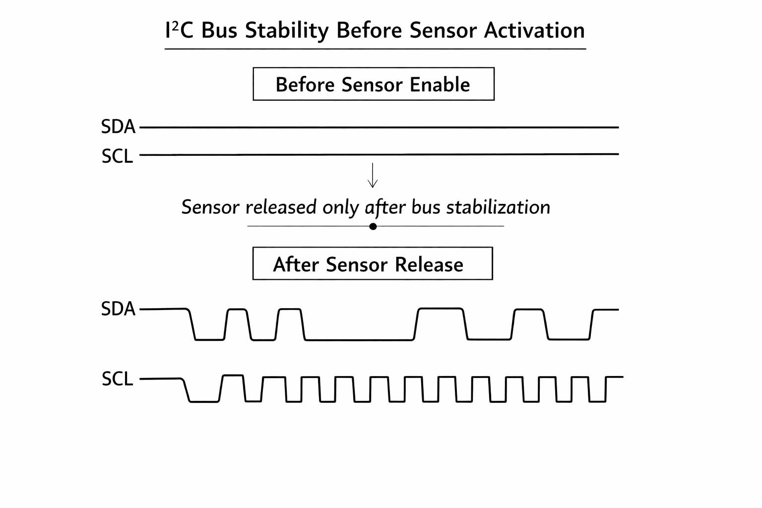
Bus stability before sensor activation
Communication buses like I2C or SPI must be stable before sensors begin transmitting. If sensors wake up before pull-ups stabilize or before the MCU configures the bus, the result can be bus contention, clock stretching deadlocks, or stuck SDA lines. To prevent this, we enforce a simple rule: sensors remain in shutdown until the bus is known to be stable. Only after the MCU configures the bus do we release sensors from shutdown, guaranteeing the first communication transaction occurs under controlled conditions.
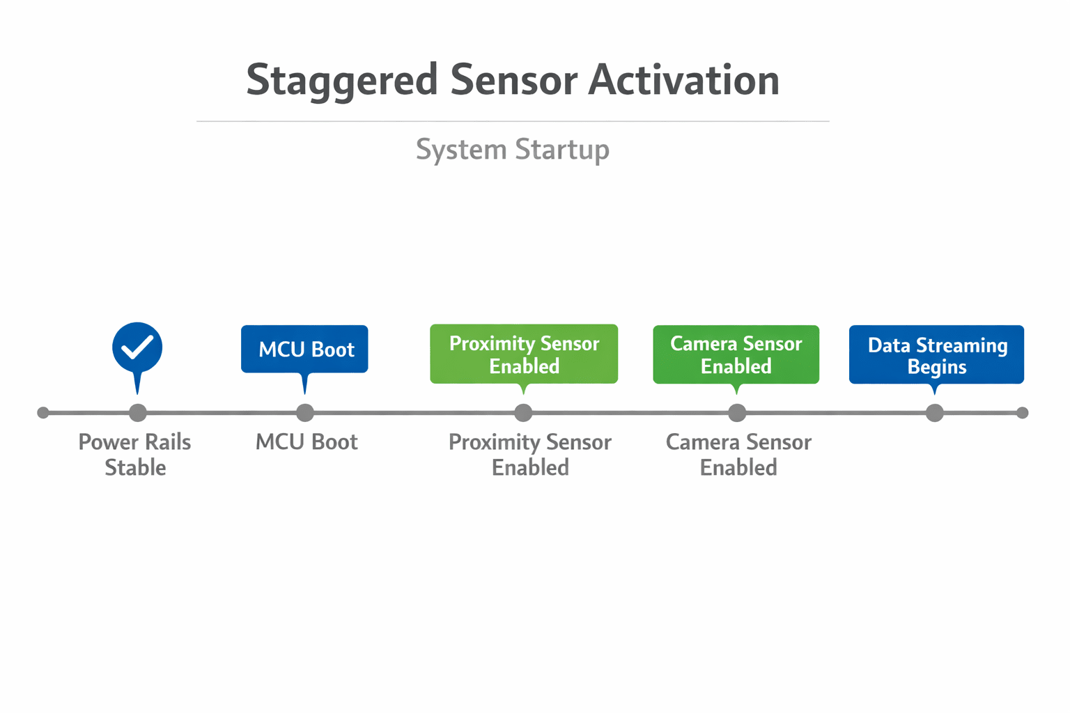
Preventing startup contention between sensors
Multiple sensors sharing a bus can compete during startup. If two devices attempt to communicate simultaneously before the MCU establishes control, unpredictable states can occur. We prevent this by staggering sensor activation, instead of powering all sensors together, we release them sequentially, proximity sensor activated, communication verified, image sensor released, data streaming enabled. This ensures only one new subsystem becomes active at a time.
Reset alignment across subsystems
Power-up order is closely related to reset behavior. If reset signals aren't aligned with rail stability, sensors may initialize incorrectly. To address this, we design a reset architecture carefully, with MCU reset controlled by the supervisor IC, sensor resets gated by power-good signals, and communication interfaces held in idle state. This ensures sensors always begin operation from a known state.
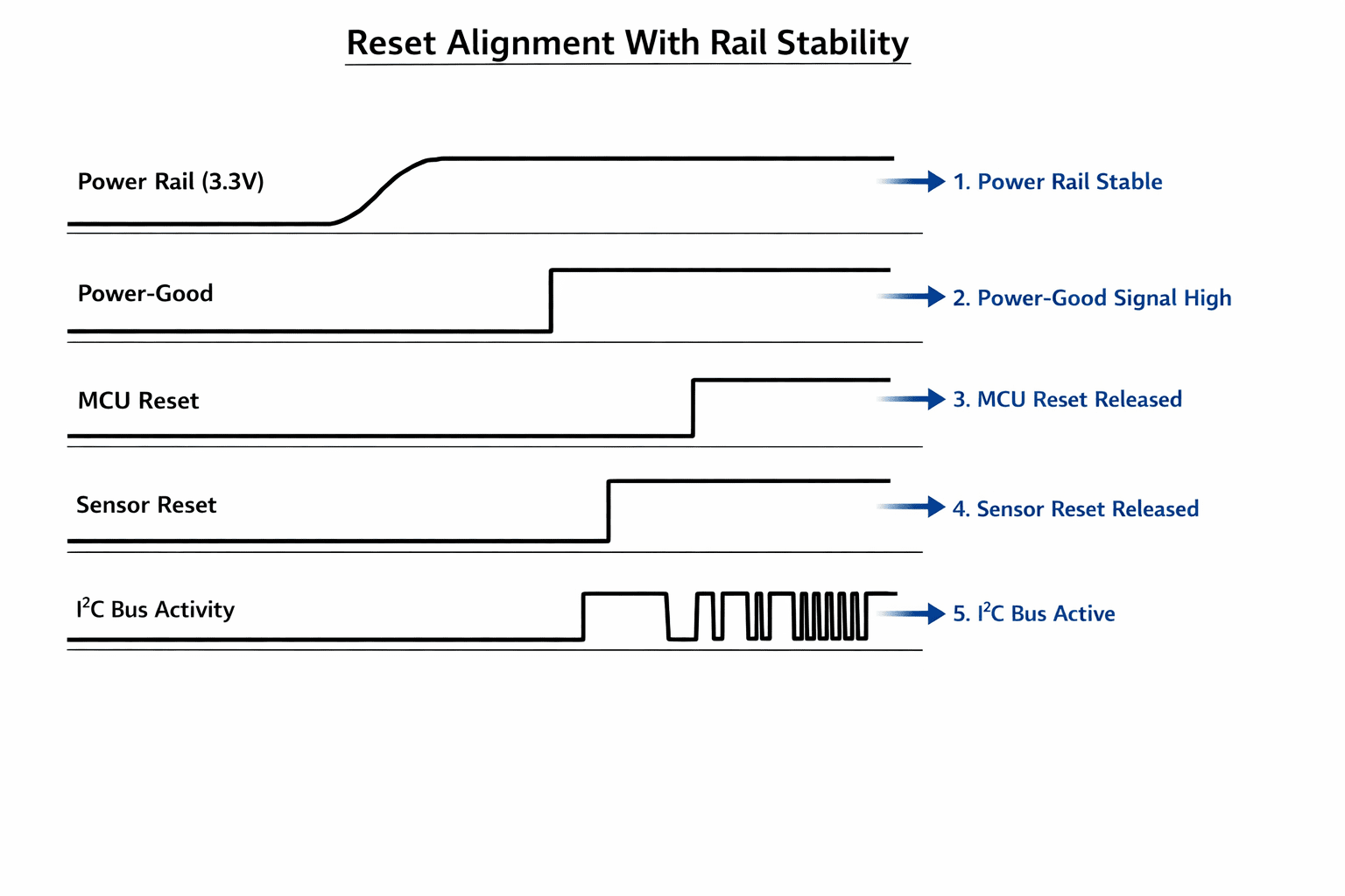
What happens when sensors are powered incorrectly
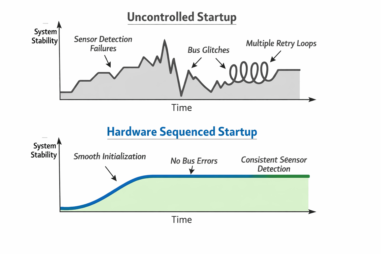
Improper startup ordering can produce sensors not responding on the bus, data streams containing invalid frames, interrupt lines stuck active, or unexpected current draw. These issues can be extremely difficult to reproduce because they depend on timing, a system might work perfectly in the lab but fail intermittently in the field. By enforcing power-up order in hardware, we eliminate those timing uncertainties.

Measuring the impact of deterministic sensor startup
After implementing hardware-enforced sensor sequencing, we observed improved boot reliability, with sensor detection during startup becoming completely repeatable and cold-start initialization errors eliminated. Faster stable initialization, since sensors started in the correct state every time and firmware no longer needed extended retry loops. Reduced bus lockups, since I2C bus errors during startup were significantly reduced. Lower startup current spikes, since staggered activation prevented multiple sensors from drawing peak current simultaneously. And more predictable debugging, since startup timing could be measured and validated with an oscilloscope.
Designing the power-up timeline
Instead of treating startup as a single event, we define it as a sequence of stages:
- Input power becomes stable
- Core MCU rail powers up
- IO rail stabilizes
- Communication buses get configured
- Sensor power domains get enabled
- Sensors get released from shutdown
- Data interfaces get activated
Each stage has clear dependencies. Nothing proceeds until the previous step is verified.
Why hardware sequencing matters in production
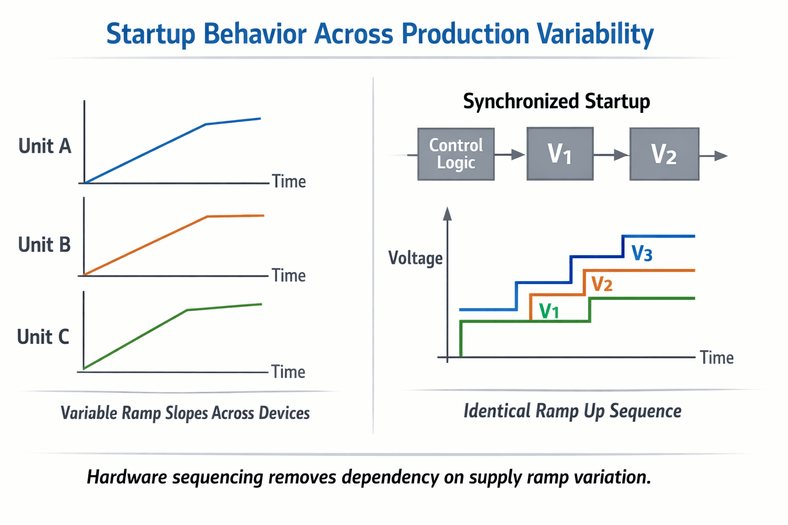
A prototype may appear stable even without strict sequencing. But production environments introduce variations, different power supplies, temperature fluctuations, component tolerance differences, aging regulators, that expose hidden weaknesses. Hardware-enforced sequencing ensures these variations don't affect startup behavior. The system behaves identically across all units.
Designing for the worst case
The true test of a startup architecture isn't ideal conditions. It's the worst case, low battery voltage, cold temperature, slow regulator ramp, brownout recovery. If sensors still initialize correctly under these conditions, the system is robust. This is why we validate sequencing with real measurements rather than assumptions.
Hardware before firmware
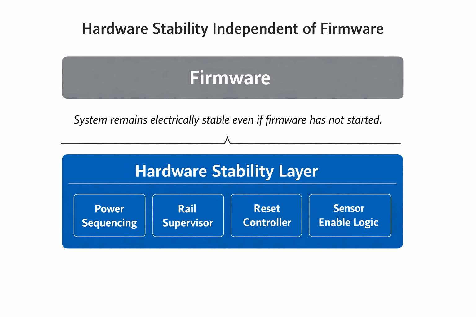
One of the key principles we follow is simple: the hardware must behave correctly even if firmware is not running. If the MCU crashes during boot, the system should remain electrically safe. Sensors shouldn't enter undefined states. Buses should remain stable. Firmware should enhance functionality, not compensate for hardware uncertainty.
The core design principle
Sensor systems aren't just collections of devices. They're coordinated electrical ecosystems, each subsystem depending on others behaving predictably. By enforcing sensor startup order in hardware, we transform boot behavior from a race condition into a controlled sequence. The result is a system that starts correctly every time, not just most of the time. And in embedded products, that difference defines the line between a prototype and a reliable product.



