
Manufacturing Intelligence: Pick-and-Place Standardization in the vBus Ecosystem
Every PCB design carries an invisible but critical responsibility: to communicate clearly with the machines that will bring it to life. The component placement list is that language. It tells automated assembly lines exactly what to place and where, converting engineering intent into manufacturing reality. When this translation is crisp, production is uneventful. When it isn't, engineers and operators spend hours debugging coordinates instead of building products.
As hardware systems become modular and manufacturing ecosystems global, the cost of inconsistent or ambiguous placement data compounds quickly. The solution isn't better guesswork at the factory, it's disciplined, predictable placement-list generation at the design stage.
The vendor portability problem
Pick-and-place machines speak different dialects. Machine formats vary, some use CSV, others proprietary formats. Origin conventions differ, board origin might be bottom-left, center, or top-left depending on the machine. Rotation standards differ too, the 0° reference varies between vendors. Units vary between metric and imperial, and column ordering varies between vendors.
The traditional approach, generate the placement list from the CAD tool, send to the manufacturer, wait for feedback on format issues, manually correct, re-send, wastes 2-5 days per design per vendor and introduces transcription errors. And we work with multiple contract manufacturers simultaneously, a quick-turn prototyping vendor, a high-volume production vendor, regional vendors for specific markets, and backup vendors for continuity, each with different equipment requiring correctly formatted data. Managing this complexity manually doesn't scale.
The vBus placement-list standard: one source, many targets
We've defined a canonical format, our internal standard from which all vendor-specific formats derive, with a clear column structure: designator, mid X, mid Y, layer, rotation, comment. Standards enforced include origin at the board geometric center, units in millimeters to two decimal places, rotation defined as 0° meaning the component marking points upward on the top layer (or downward on the bottom), increasing counter-clockwise, explicit top or bottom layer designation, designators matching the schematic exactly, and a human-readable comment field for verification.
This gives us a vendor-neutral format that's human-readable for visual verification, uses a consistent rotation reference that eliminates the most common placement error, and includes complete information any vendor might need.
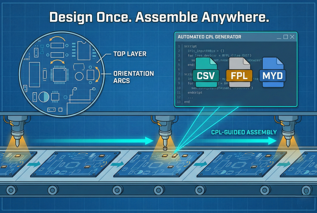
From this master format, we generate vendor-specific formats automatically through a Python-based translator that reads the master data and applies transformation rules:
- Origin translation converting from center origin to bottom-left
- Rotation conversion flipping counter-clockwise to clockwise where needed
- Column reordering mapping master columns to the vendor's template
The output is vendor-ready data in their preferred format, generated in seconds.
We maintain a profile library for each manufacturer, capturing machine format specification, origin convention, rotation standard, unit preference, and special requirements like fiducial handling or panel notation. A designer selects the vendor profile and the script generates appropriate output automatically. A new vendor just needs a profile added once, then it's usable forever.
Component library integration
Placement accuracy starts in component libraries. Each footprint includes standardized placement data:
- A pick point defining the X/Y offset from footprint origin to component center where the nozzle grabs it
- Component height for nozzle clearance
- A rotation offset correction factor if the component's 0° differs from the standard orientation
For an LQFP144 package, the pick point sits at the package center, height reflects the package thickness plus clearance, and rotation offset is zero with pin 1 at the standard position. For a 0402 capacitor, the pick point is the component center, height is the standard 0402 thickness, and rotation offset is zero since there's no preferred orientation. When a component is placed in the PCB layout, placement data flows automatically to the output, no manual entry, no transcription errors.
Consistent orientation rules get enforced for polarized components: ICs with pin 1 toward the top-left of the board, electrolytic capacitors with the positive terminal toward top or right, diodes and LEDs with the cathode marking toward right or bottom, connectors with pin 1 toward the board edge. Non-polarized components follow a standard orientation where practical, long axis horizontal, which reduces pick-and-place rotation movements for faster assembly. Design rule checks verify component orientation and flag deviations for review, ensuring the placement data reflects intentional design decisions, not layout accidents.
Fiducial management
Pick-and-place machines use fiducials, optical reference marks, for board alignment. Global fiducials are board-level references, typically three, non-collinear, establishing the board coordinate system and correcting for panel placement variation, usually positioned at corners on opposite board edges. Local fiducials are component-level references for high-precision parts like fine-pitch QFN packages or BGAs, used for sub-pixel placement accuracy. Fiducials get included in the placement data with special designation so the machine recognizes them and uses them for optical alignment before component placement.
Our vBus standard positions carrier boards with consistent fiducial placement, opposite corners, 5mm from board edges, 1mm diameter copper circles free of soldermask and silkscreen obstruction. Manufacturers familiar with our fiducial conventions need less setup time and hit fewer alignment issues.
Panelization considerations
Production volumes often use panelized PCBs, multiple boards arranged in an array on a single panel. Array generation replicates the master placement data for each panel position, calculating an offset based on panel layout, board spacing, and rail width. Components in the array receive a position prefix, board 1 gets U1, C1, R1, board 2 gets U1_2, C1_2, R1_2, and so on, enabling traceability during testing, if board 2 in the panel fails, the designators identify exactly which position. Panelized assembly also requires panel-level fiducials, located on the panel rails outside individual boards, used for panel registration on the conveyor, separate from individual board fiducials.
Quality assurance integration
Before sending data to the manufacturer, automated validation runs coordinate sanity checks confirming all X/Y coordinates fall within the board outline, rotation verification confirming polarized components sit at standard orientations, a designator cross-check confirming every schematic component has a corresponding entry and vice versa, and layer verification confirming components sit on appropriate layers. A validation report gets generated automatically and reviewed before release.
An internal CPL preview tool renders the data visually, drawing component outlines at specified coordinates with rotation shown via orientation indicator, overlaid on the PCB layout image for comparison, giving a quick visual scan that catches obvious placement errors. Modern EDA tools also generate a 3D assembly preview from the placement data, showing all components in position with rotation and orientation visible, checking for mechanical interference, and validating accuracy before manufacturing.
Manufacturing feedback loop
Manufacturers provide feedback on data quality through acceptance testing, reporting whether the import succeeded, whether coordinates align with pads on the actual board, and whether polarized parts are oriented correctly. First article inspection photographs and reviews the initial assembled board, validating placement accuracy and documenting any rotation or position errors for correction. Continuous improvement incorporates this feedback into conversion scripts and component library metadata, issues get corrected at the source, not repeated.
Placement data also informs assembly optimization. Component grouping by similar package and feeder reduces feeder changes during assembly and speeds up placement cycle time, though manufacturers can re-sequence if needed. Nozzle planning based on component heights enables batch nozzle changes and reduces assembly interruptions.
Metrics and continuous improvement
CPL first-pass acceptance rate, the percentage accepted by the manufacturer without format corrections, targets 100% with vendor profile accuracy and currently runs above 98%, with occasional edge cases for new vendors. Placement error rate runs under 2 errors per 1000 placements against an industry average of 5-10, since standardization reduces ambiguity. Assembly setup time, from data receipt to production start, dropped from 4-8 hours of manual data correction down to 30-60 minutes of machine programming only.
Time savings per design run roughly 95%, from 3-5 hours of manual generation and correction per vendor down to about 5 minutes automated. At scale, across 4 vendors and 20 designs a year, that's the difference between 240-400 manual hours annually and about 7 automated hours, savings of 230-390 engineering hours a year. Fewer placement errors also mean fewer rework cycles, fewer assembly delays, and higher first-pass yield.
Conclusion: standardization as manufacturing excellence
Pick-and-place standardization might seem like a mundane manufacturing detail, but it's fundamental infrastructure that enables our scaling strategy. By defining a canonical format, automating vendor-specific conversions, and integrating placement data into component libraries, we've transformed assembly data from a source of delays into a competitive advantage.
As our vBus ecosystem grows and we engage more manufacturing partners globally, our standardization framework scales effortlessly. New vendors integrate in hours, not days. New designs generate correct assembly data automatically. Manufacturing quality remains consistently high regardless of production location. This is manufacturing intelligence, where data standards, automation, and process discipline combine to create reliable, repeatable, scalable production capability.



