
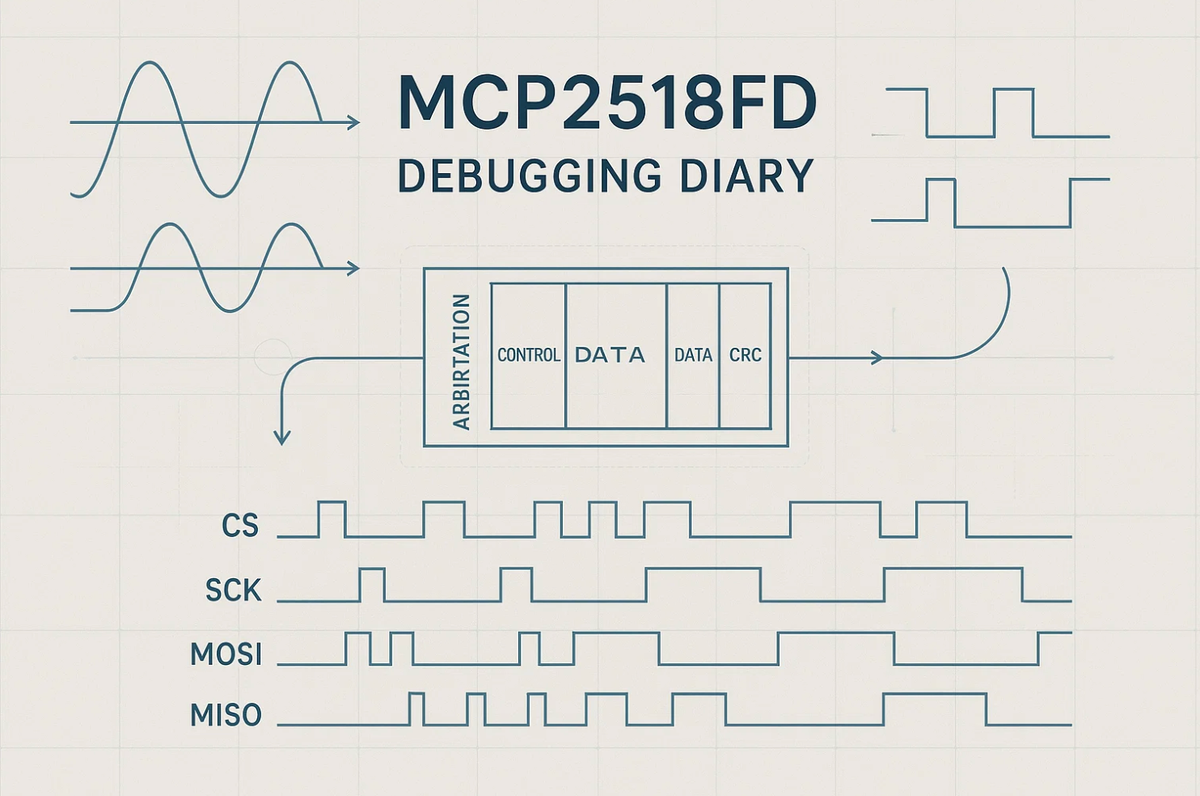
MCP2518FD Debugging Diary
The Microchip MCP2518FD is a popular external CAN-FD controller that interfaces with the host MCU over SPI. It performs well under controlled conditions, but its field reliability comes down almost entirely to the quality of the host-side driver. This post documents technical findings, failure signatures, and recovery patterns validated through lab testing, focused on SPI timing margins, interrupt consistency, and FIFO-level correctness guarantees. These patterns now form the backbone of a deterministic, fault-tolerant CAN-FD layer used inside Hoomanely's distributed embedded systems.
The real integration challenge
External SPI-based network controllers seem conceptually simple: the MCU sends configuration commands, the controller manages the CAN-FD physical layer, and interrupts notify the MCU of events. In practice, the boundary between SPI and the MCP2518FD's internal state machine creates a narrow window where timing, synchronization, and FIFO transitions have to align precisely.
During bring-up and stress testing, small deviations in timing or state sequencing can cause inconsistent RX and TX state visibility, incomplete or misaligned SPI responses, premature interrupt assertion, FIFO pointer drift, and stale frame reads. None of these are hardware defects, they're typical of a complex state machine exposed over SPI. The goal is a systematic driver design that stays correct even when communication timing shifts or FIFO state evolves rapidly.
The real integration challenge, in three parts
The MCP2518FD performs internal operations, CAN arbitration, bit timing, CRC verification, FIFO movement, asynchronously relative to the MCU's SPI domain, and that asynchrony creates three practical challenges. Temporal desynchronization, where internal controller state can shift between two SPI transactions even if they happen back to back. Partial visibility windows, since interrupt lines and registers don't always update atomically at the same instant, which isn't a flaw, it's inherent to any external peripheral with deep internal FIFO structures. And burst-read sensitivity, since SPI burst reads have to respect boundaries the controller defines, and violating them or underestimating CS timing can return data starting at an unexpected internal offset.
A robust driver has to treat all three as normal conditions, not edge cases.
SPI timing: the foundation of reliability
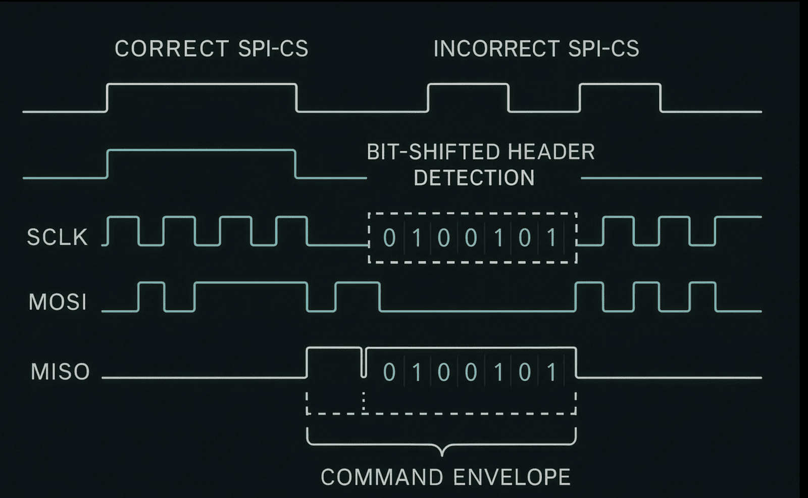
SPI timing is the most deterministic layer here, and also the most fragile when misconfigured. Common issues include insufficient CS setup time before the first SCK, DMA-driven SPI that doesn't maintain strict CS sequencing, MCU latencies violating required inter-command spacing, and overly aggressive SPI frequencies without validating device margins. These produce subtle corruption, not full transfer failure, but valid opcodes followed by invalid header bytes, header bytes followed by misaligned payload, and 0x00 or 0xFF patterns from misclocked first bits.
A driver should encapsulate every transaction inside a strict envelope controlling CS assertion timing, transfer atomicity, and post-transfer validation:
bool spi_transfer_hardened(const uint8_t *tx, uint8_t *rx, size_t len) {
    gpio_clear(CS_PIN);
    delay_cycles(CS_SETUP_CYCLES); // enforces minimum tCSS
    bool status = spi_transfer_blocking(tx, rx, len);
    gpio_set(CS_PIN);

    // MCP2518FD never uses 0x00 or 0xFF as a valid header response
    if (!status) return false;
    if (rx[0] == 0x00 || rx[0] == 0xFF) return false;

    return true;
}
This prevents the most common class of misalignment-induced failures.
Interrupt handling: consistency through multi-stage validation
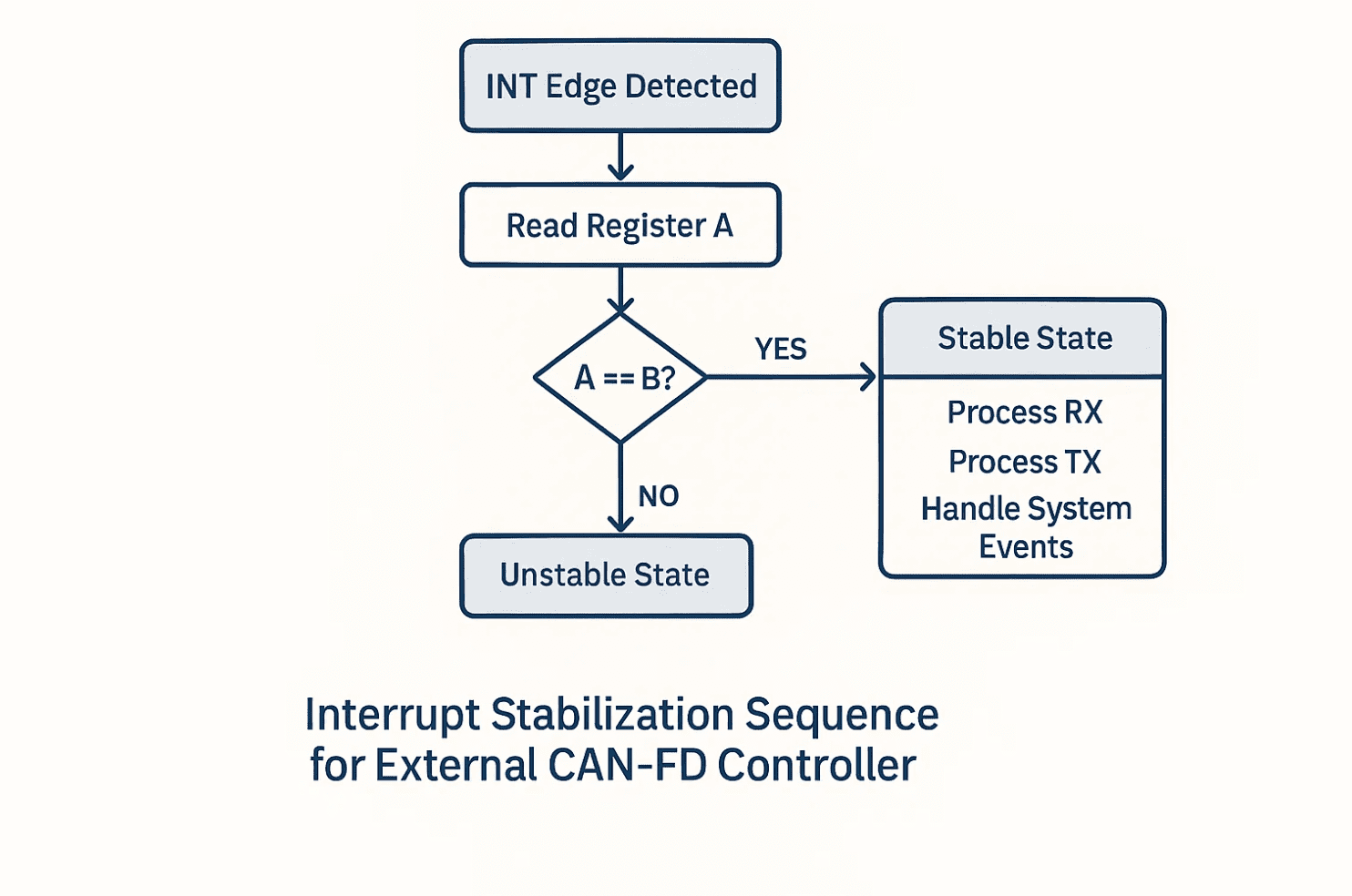
The MCP2518FD asserts an external INT pin when events occur, but INT assertion, status register update, and FIFO pointer movement aren't strictly simultaneous. Reading the interrupt register once isn't enough to confirm stability, inconsistencies between successive reads indicate a transition window, not a fault, but the driver has to handle those windows defensively:
void mcp2518fd_handle_interrupt() {
    uint32_t irq_a = read_reg(CAN_INT);
    uint32_t irq_b = read_reg(CAN_INT);

    if (irq_a != irq_b) {
        // State is changing; the safest action is a FIFO boundary re-sync
        reset_rx_tx_fifos();
        return;
    }

    if (irq_a & RX_INT) handle_rx();
    if (irq_a & TX_INT) handle_tx();
    if (irq_a & SYS_INT) handle_system_events();
}
This dual-read pattern ensures the handler only acts on stable state snapshots, never on transient conditions.
RX integrity: every frame must be proven correct
A CAN-FD frame carries several pieces of metadata, ID, flags, DLC, CRC, alongside the payload. RX corruption is rarely total, more often just the header or length field is wrong. To keep invalid frames from propagating upward, the RX pipeline needs header integrity checks, DLC-to-byte-length validation, CRC verification where applicable, and FIFO index sanity checks:
bool extract_rx_frame(can_frame_t *frame) {
    uint8_t hdr[8];
    if (!spi_transfer_hardened(cmd_read_rx_header, hdr, sizeof hdr))
        return false;

    uint8_t dlc = hdr[2] & 0x0F;
    uint16_t expected_len = dlc_to_length(dlc);
    if (expected_len > MAX_CANFD_PAYLOAD) return false;

    uint8_t payload[64];
    if (!spi_transfer_hardened(cmd_read_rx_payload, payload, expected_len))
        return false;
    if (!crc_validate(payload, expected_len))
        return false;

    assemble_frame(frame, hdr, payload);
    return true;
}
This keeps malformed frames from slipping through on subtle misreads.
A deterministic recovery pipeline
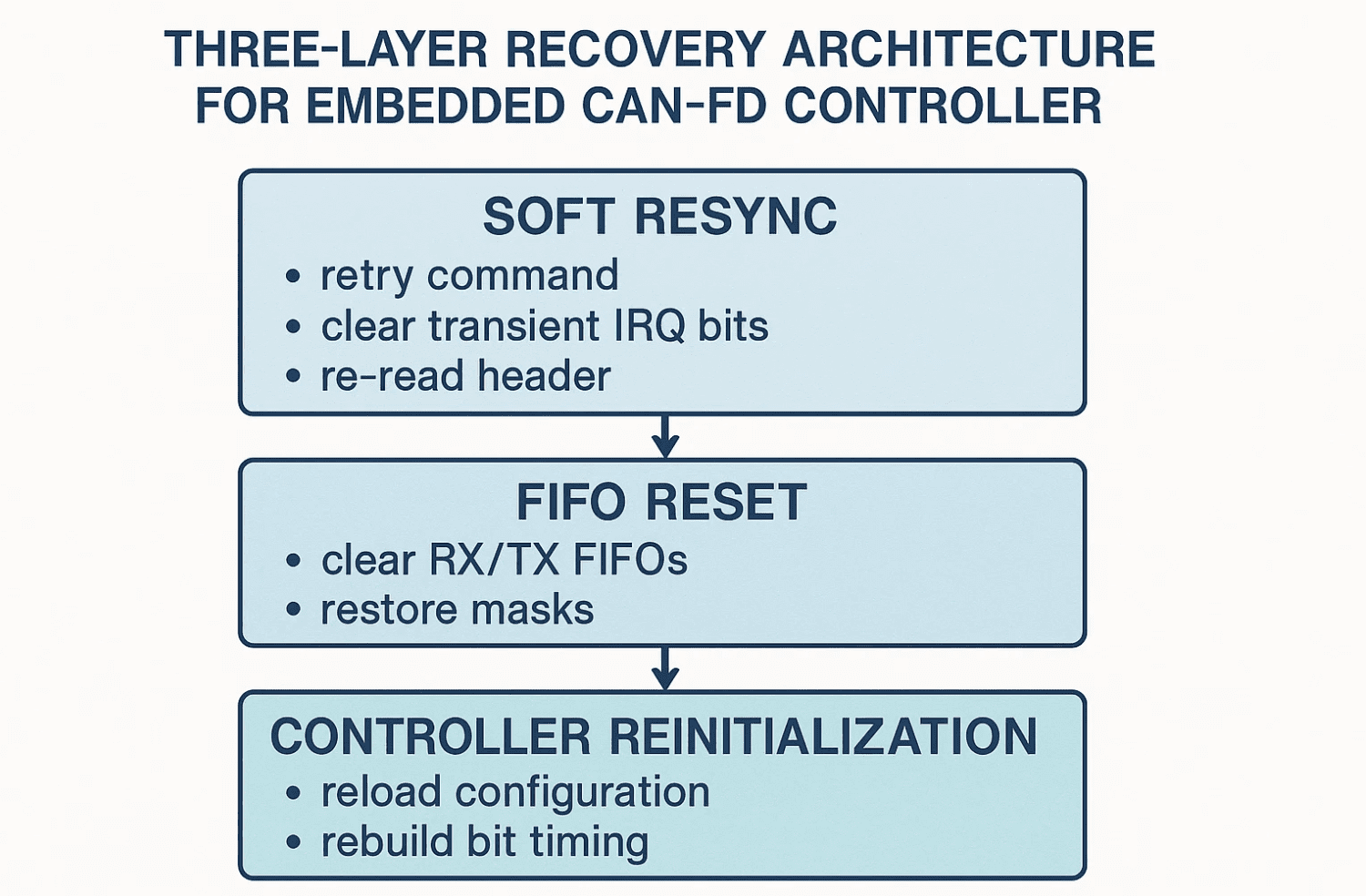
Recovery is a structured escalation, not a full controller reset for every anomaly. Soft resynchronization applies when header inconsistency or minor SPI misalignment is suspected, re-reading the header, clearing transient flags, and retrying. FIFO reset applies when RX and TX pointers desynchronize, clearing the FIFO and restoring masks. Full reinitialization applies when inconsistency persists or interrupt state stays unstable, reconfiguring the controller and rebuilding timing parameters. This keeps recovery targeted instead of destructive.
Applicability to Hoomanely's ecosystem
In our architecture, devices interact across heterogeneous power domains, varying load patterns, and noise-prone consumer environments, which makes bus-level determinism essential for coordinating state between multiple sensor modules, exchanging time-sensitive updates between local inference nodes, orchestrating peripheral subsystems fault-tolerantly, and preventing intermittent corruption from cascading in long-running systems.
The patterns here reflect real deployment constraints, where reliability isn't measured by ideal conditions but by graceful handling of non-ideal ones. By designing the MCP2518FD driver around verification, stability windows, and controlled recovery, communication integrity holds up despite fluctuating electrical or timing conditions.
Conclusion
The MCP2518FD is fully capable of stable, deterministic CAN-FD operation, but only paired with a host driver that accounts for strict SPI envelope timing, interrupt and register synchronization windows, RX validation before acceptance, and structured recovery processes. These practices, validated through lab testing and aligned with real operational realities, form the backbone of a reliable CAN-FD communication layer across Hoomanely's hardware ecosystem.



