Preventing Accidental Feature Activation in Hardware

Why gating and physical safeguards matter before firmware ever gets involved
A feature that turns on at the wrong time is not just a firmware bug.
In real embedded products, accidental activation can create electrical stress, false sensor readings, unexpected power draw, startup instability, or confusing factory-test failures. Sometimes the feature itself is harmless during normal operation, but dangerous during boot, reset, brown-out, assembly, or service handling.
This is especially true in compact multi-sensor systems where several hardware blocks share the same power source, control lines, connectors, and physical enclosure. An LED driver, camera rail, wireless interface, actuator, sensor excitation circuit, or communication transceiver may be completely valid when intentionally enabled. But if it turns on before the system is ready, it can disturb everything around it.
At Hoomanely, we treat feature activation as a hardware responsibility first and a firmware responsibility second.
Firmware may request a feature.
Hardware should decide whether that request is electrically safe.
That difference matters.
Because firmware does not exist during the earliest part of boot. It may not run during brown-out. It may crash during development. It may be absent in the factory. It may be replaced during OTA updates. If the only thing preventing a feature from activating is a line of software, then the feature is not truly controlled.
A product-grade system needs physical safeguards.
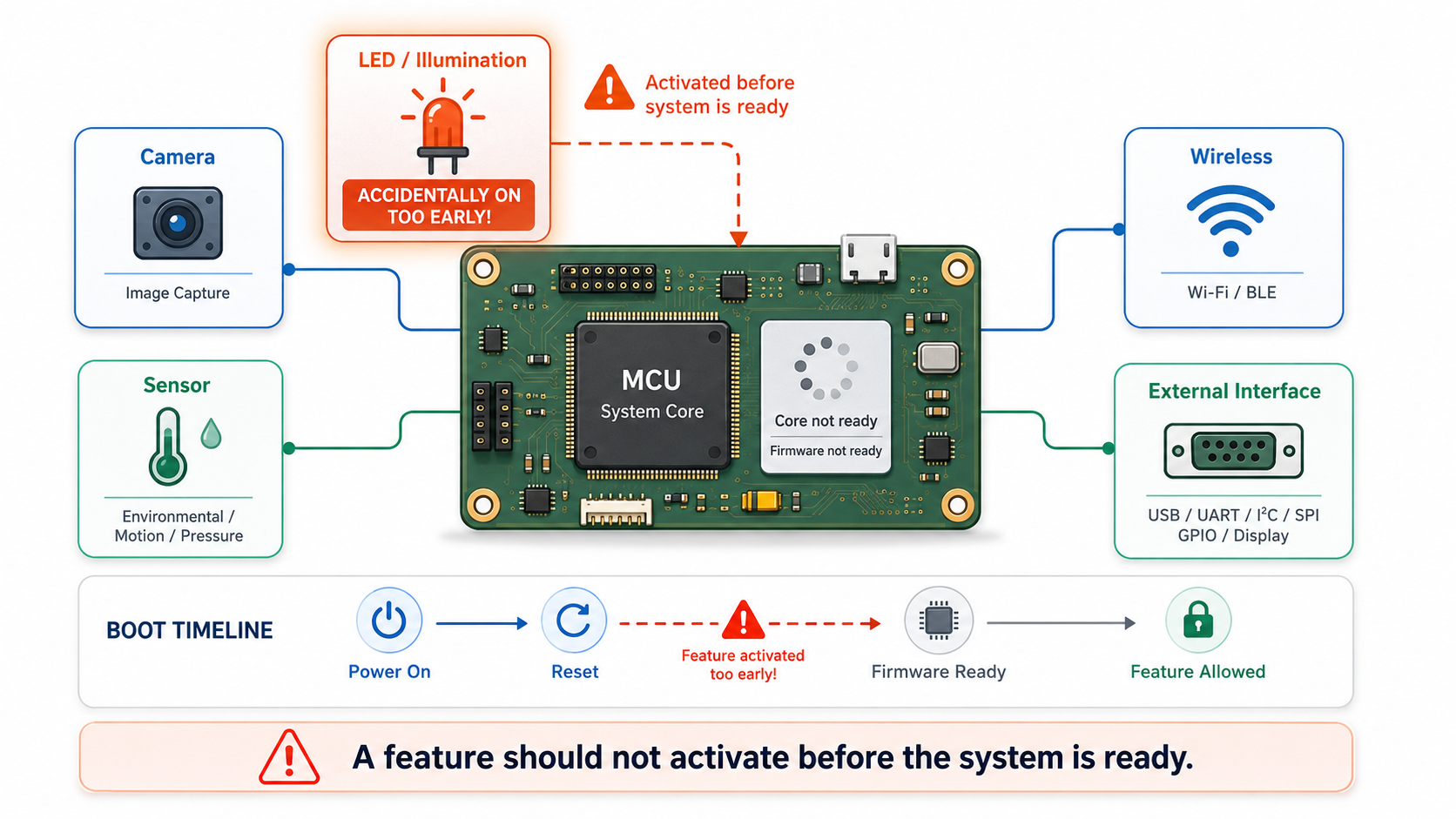
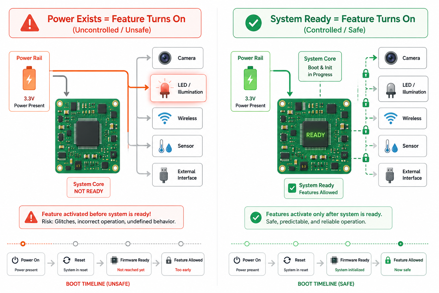
Features Should Not Wake Up Just Because Power Exists
One of the most common prototype habits is connecting a feature directly to a rail and assuming firmware will manage the rest.
The board powers up. The MCU configures GPIOs. The firmware sets enables low or high as needed. In a controlled lab environment, this usually works.
But real hardware has a period before firmware takes ownership.
During this time, GPIOs may be high impedance, reset lines may be undefined, level shifters may pass unknown states, and pull resistors may be missing or incorrectly placed. If a feature-enable pin floats into the active state, the feature can turn on without permission.
This is why every significant feature should have a safe hardware default.
For most features, the safest default is OFF.
That means:
- IR illumination should remain off until intentionally enabled.
- Camera power rails should not start randomly during boot.
- Wireless modules should not transmit before configuration.
- LED indicators should not receive false data during reset.
- External interfaces should not drive a bus before ownership is clear.
- Sensor shutdown pins should remain in a known state.
The principle is simple: power presence should not equal feature permission.
A feature should require a valid enable condition, not merely a powered rail.
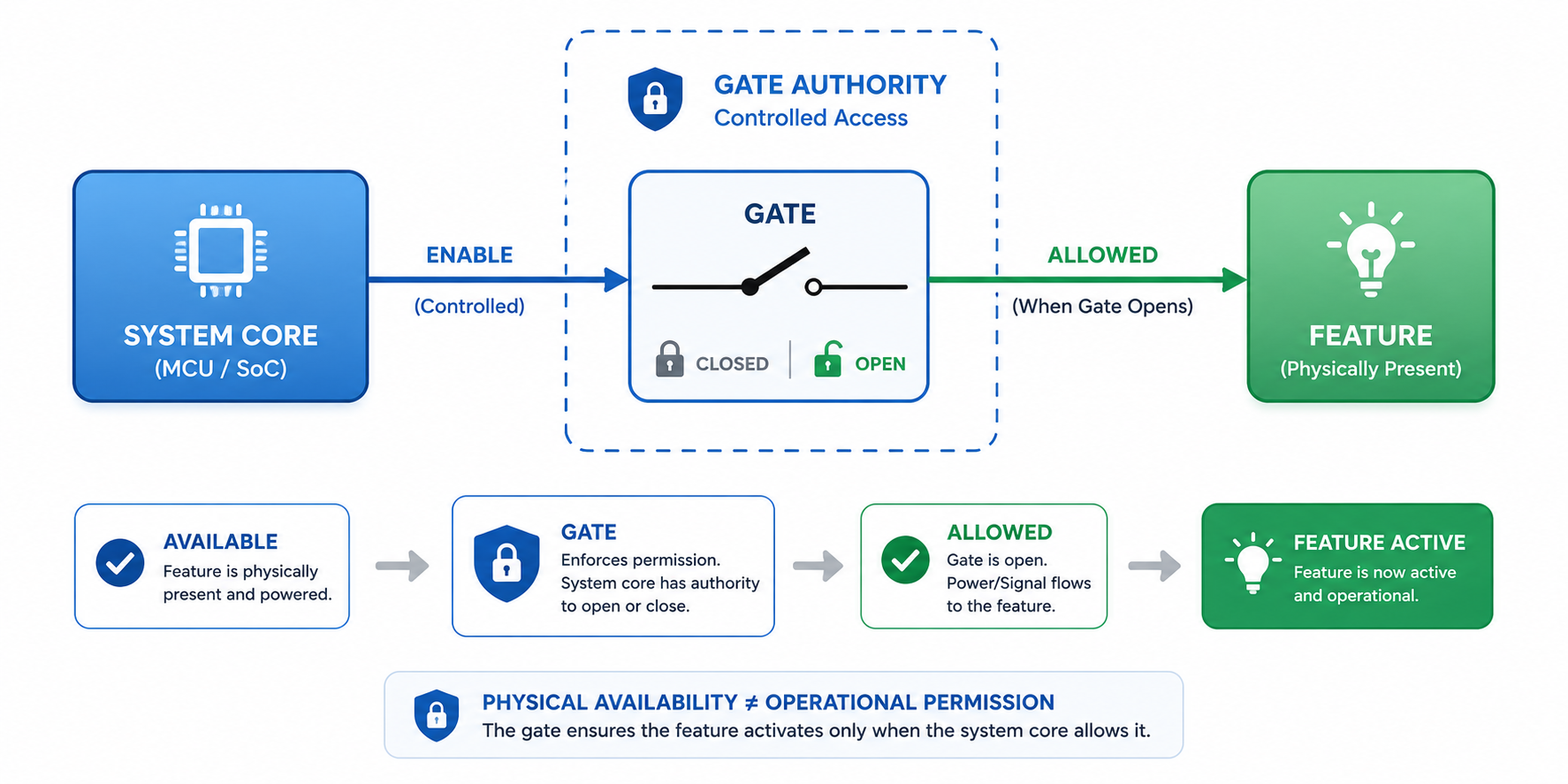
Gating Is the Boundary Between “Available” and “Allowed”
Gating is not just about saving power. It is about creating authority.
A gated feature is electrically available, but not allowed to operate until a deliberate control condition is satisfied.
This control condition can come from a GPIO, supervisor, PMIC, reset signal, latch, load switch, or combination of multiple signals. The key point is that the gate creates a hard boundary between the system core and the feature.
In a Hoomanely hardware architecture, gating is used to separate features that may disturb startup, measurement, communication, or power stability.
For example, a sensor board may contain several controlled sections: imaging power rails, proximity sensor enable, LED/illumination paths, level-shifter output enables, communication transceiver standby, and status indicator power. In the EverBowl sensor schematic, this type of multi-feature structure is visible through separate regulated domains, sensor rails, level translators, reset supervision, CAN transceiver control, and feature enable paths.
This architecture is useful because each feature can be brought into the system intentionally rather than all at once.
A good gate answers three questions:
- Who is allowed to activate this feature?
- What is the default state before firmware runs?
- What happens if the control signal becomes invalid?
If the answer to the third question is “the feature may turn on,” the gate is not safe enough.
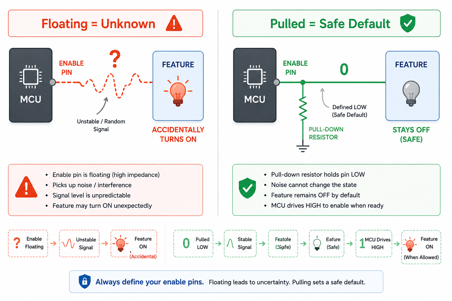
Pull Resistors Are Small Parts With Big Responsibility
Pull-up and pull-down resistors are often treated as minor components, but in feature-safety design they are one of the most important safeguards.
They define what the system does when nobody is actively driving the line.
That “nobody” condition happens often:
- during MCU reset,
- before firmware pin configuration,
- during programming,
- during brown-out,
- when a cable is disconnected,
- when a board is partially assembled,
- or when a level shifter is disabled.
A floating enable line is an invitation for accidental activation.
For feature enables, shutdown pins, chip selects, output enables, and boot-mode lines, the resistor direction should be chosen based on the safest state, not based on routing convenience.
A few practical examples:
- Active-high enable lines should usually have pull-downs.
- Active-low reset lines should usually have pull-ups or supervisor control.
- SPI chip selects should usually be pulled inactive.
- Level-shifter OE pins should default to disabled.
- Transceiver standby pins should default to a non-disruptive state.
- LED or illumination control lines should default off.
The goal is not just to prevent noise. The goal is to ensure that every feature has a physical opinion before the firmware starts speaking.
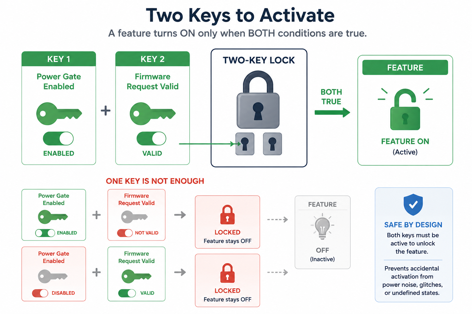
Two-Step Activation Is Better Than One GPIO
For low-risk features, one enable pin may be enough.
For features that can affect power, optics, user-facing behaviour, field safety, or measurement reliability, single-signal control is often too weak.
A better strategy is two-step activation.
The feature only turns on when two independent conditions are true. For example:
- A regulator enable must be active.
- A local feature enable must also be active.
Or:
- The system must be out of reset.
- The firmware feature command must be valid.
Or:
- The PMIC must declare rails stable.
- The MCU must request activation.
This prevents accidental activation caused by one floating line, one firmware glitch, or one partially powered logic domain.
Two-step activation is especially useful for features such as illumination, camera rails, wireless transmitters, external power outputs, or anything that should never activate during reset or factory handling.
The design does not need to be complicated. Sometimes a transistor, load switch enable, or simple logic gate is enough.
What matters is that activation requires intent, not coincidence.
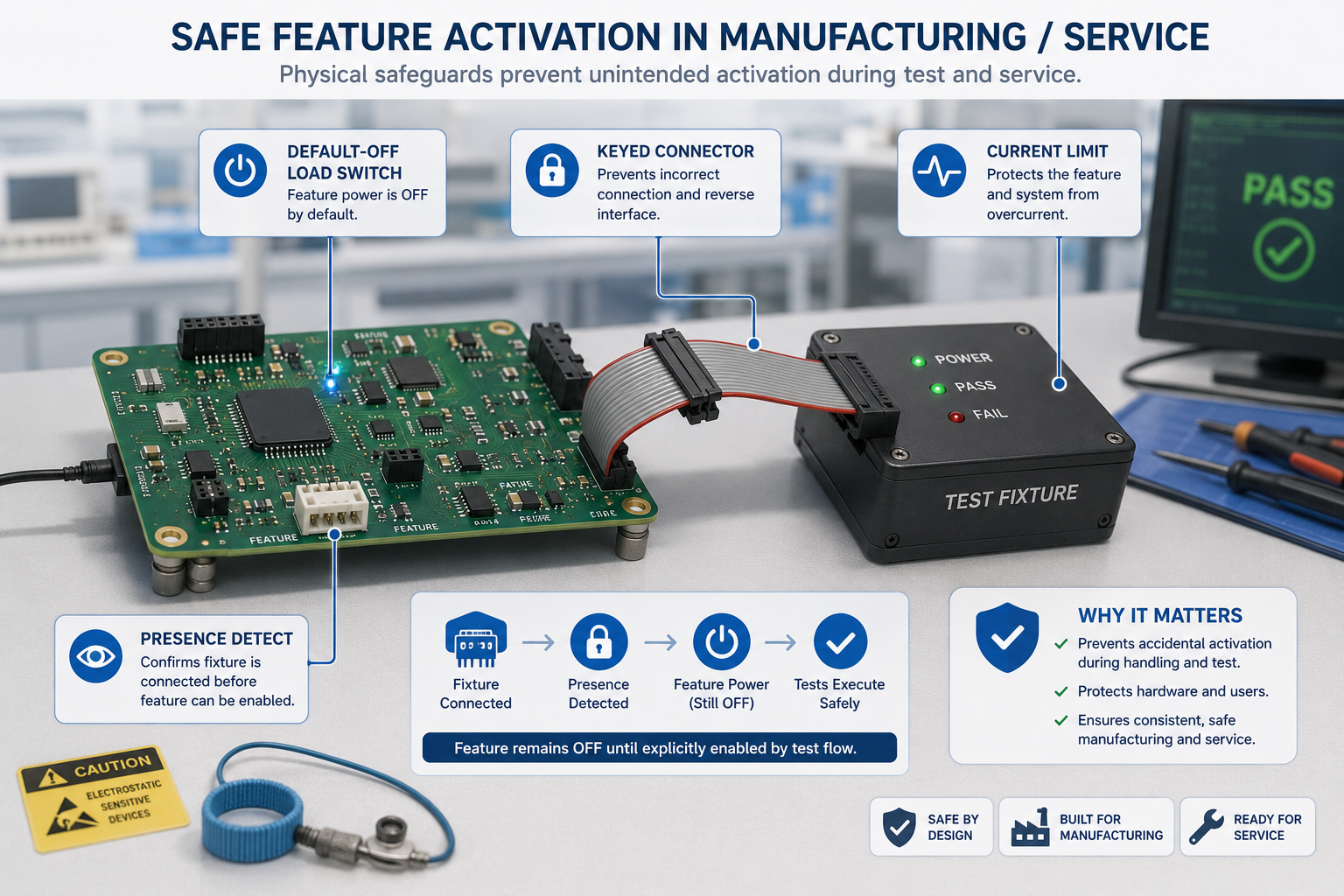
Physical Safeguards Help During Manufacturing and Service
Accidental activation does not only happen in normal use.
It also happens during assembly, testing, flashing, rework, and field servicing.
A technician may connect one board before another. A debug fixture may power only part of the system. A ribbon cable may be inserted while the board is already powered. A test jig may hold the MCU in reset while external rails remain active.
In these conditions, firmware may not be available to enforce safety.
Physical safeguards become the first line of defence.
Useful safeguards include:
- default-off load switches,
- current-limited feature rails,
- keyed connectors,
- protected enable pins,
- series resistors on control lines,
- reset-supervised enables,
- connector presence detection,
- and local pull networks on detachable modules.
These measures reduce dependence on perfect human process.
The board becomes more tolerant of real manufacturing behavior.
At Hoomanely, this is a recurring design theme: the hardware should not assume the factory, technician, or user follows an ideal sequence every time. It should remain safe even when the sequence is imperfect.
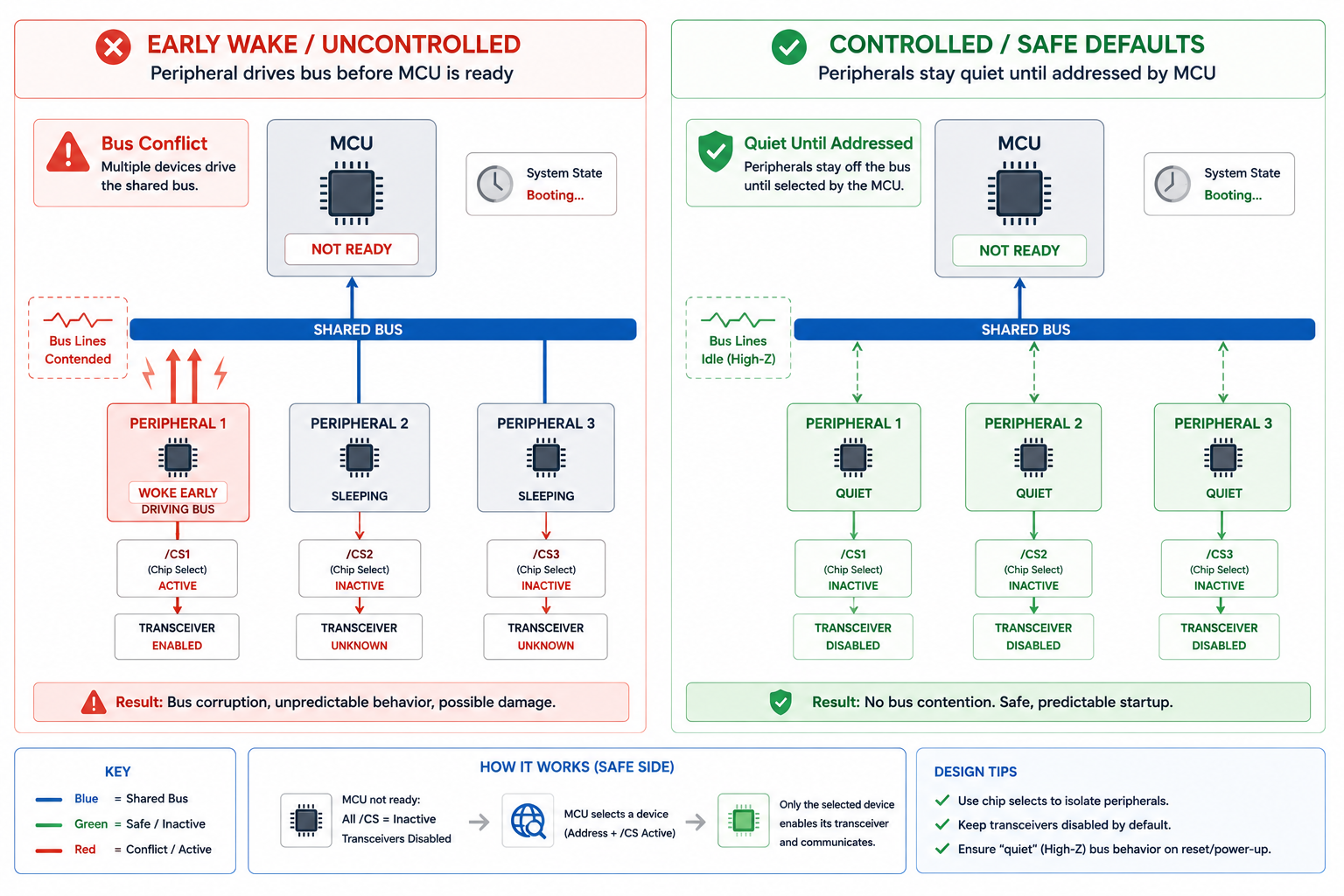
Preventing False Activation on Shared Interfaces
Shared interfaces are common places where accidental feature activation begins.
SPI, I2C, UART, CAN, GPIO expanders, and level-translated buses can all create unintended behavior if one device wakes before the bus owner is ready.
A floating chip select may wake an SPI device.
A UART line may look like a start bit during boot.
An I2C device may stretch or hold the bus while the controller is still resetting.
A CAN transceiver may disturb the bus if standby control is not defined.
This is why shared interfaces need inactive defaults.
The bus should start quiet.
Devices should be deselected.
Transmitters should remain disabled.
Transceivers should stay in standby unless explicitly enabled.
The controller should gain ownership before peripherals are allowed to drive shared lines.
This is not only a signal-integrity concern. It is a system-authority concern.
A device that can talk before it is addressed can create behavior that looks like firmware instability but actually begins in hardware.
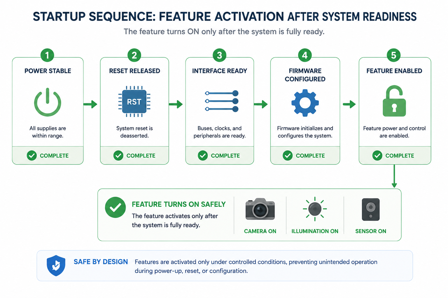
Feature Activation Should Follow System Readiness
A feature should not activate just because its own rail is stable.
It should activate when the system is ready to handle the consequences.
For example, powering a camera rail is not enough. The clock path, reset line, interface receiver, firmware driver, memory buffer, and power budget must also be ready.
Similarly, enabling an illumination circuit requires more than applying voltage to the LED driver. The exposure pipeline, current budget, thermal behavior, and user-facing state must be valid.
This is why feature enables should often be tied to system readiness signals.
A useful activation sequence looks like this:
Power rail valid.
Reset released.
Interface quiet.
Firmware configured.
Feature command accepted.
Feature enabled.
This may seem slower than simply toggling a GPIO, but the result is a system that behaves consistently.
Milliseconds of sequencing are usually cheaper than hours of debugging.
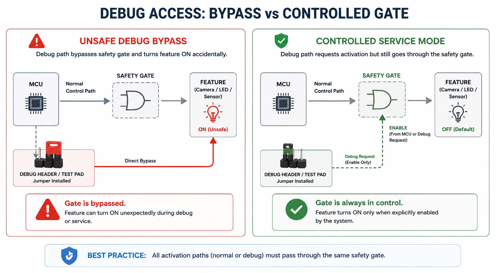
Do Not Let Debug Paths Bypass Safety
Development boards often include jumpers, headers, debug buttons, direct enables, and factory override lines.
These are useful, but they can accidentally bypass the safety architecture.
A debug jumper that directly forces a regulator on may be acceptable in early EVT, but dangerous if it survives into production without clear intent. A test pad that can enable illumination without the MCU may create unexpected behavior during fixture testing. A programming mode that leaves feature rails active may produce confusing current measurements.
Debug access should exist, but it should not quietly defeat the same safeguards the product depends on.
A good rule is this:
Debug paths may observe and request. They should not permanently bypass safety unless explicitly designed as a controlled service mode.
That service mode should be documented, labelled, and physically hard to enter accidentally.
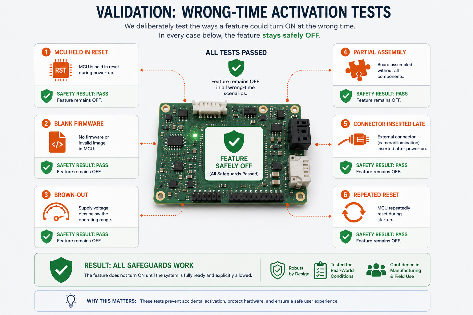
Validation Must Try to Activate Features at the Wrong Time
A design is not proven safe merely because features work when enabled correctly.
It must also be tested for what happens when activation is attempted incorrectly.
During validation, engineers should intentionally test:
- power-on with MCU held in reset,
- firmware absent or blank,
- brown-out during feature enable,
- partial board assembly,
- connector insertion during standby,
- invalid GPIO states,
- repeated reset while feature rails are active,
- and factory fixture mis-sequencing.
The question is not only “does the feature turn on?”
The better question is:
Can the feature turn on when it should not?
If the answer is yes, the design needs stronger gating or better physical safeguards.
Final Thoughts
Accidental feature activation is rarely caused by one obvious mistake.
It usually appears when hardware assumes firmware will always be present, GPIOs will always be initialized, power rails will always sequence cleanly, and manufacturing will always happen in the expected order.
Real products do not live in that ideal world.
They boot, reset, brown-out, get serviced, get reprogrammed, and pass through factory fixtures. During those moments, features need physical boundaries.
At Hoomanely, our hardware architecture approach is built around a simple idea: features should be available, but not automatically trusted.
A feature should earn permission to activate through stable power, valid reset state, defined control signals, and clear system ownership.
That is what gating and physical safeguards provide.
They turn feature activation from an assumption into a controlled decision.
And in embedded product design, that difference is often what separates a reliable system from a prototype that only behaves when everything happens perfectly.