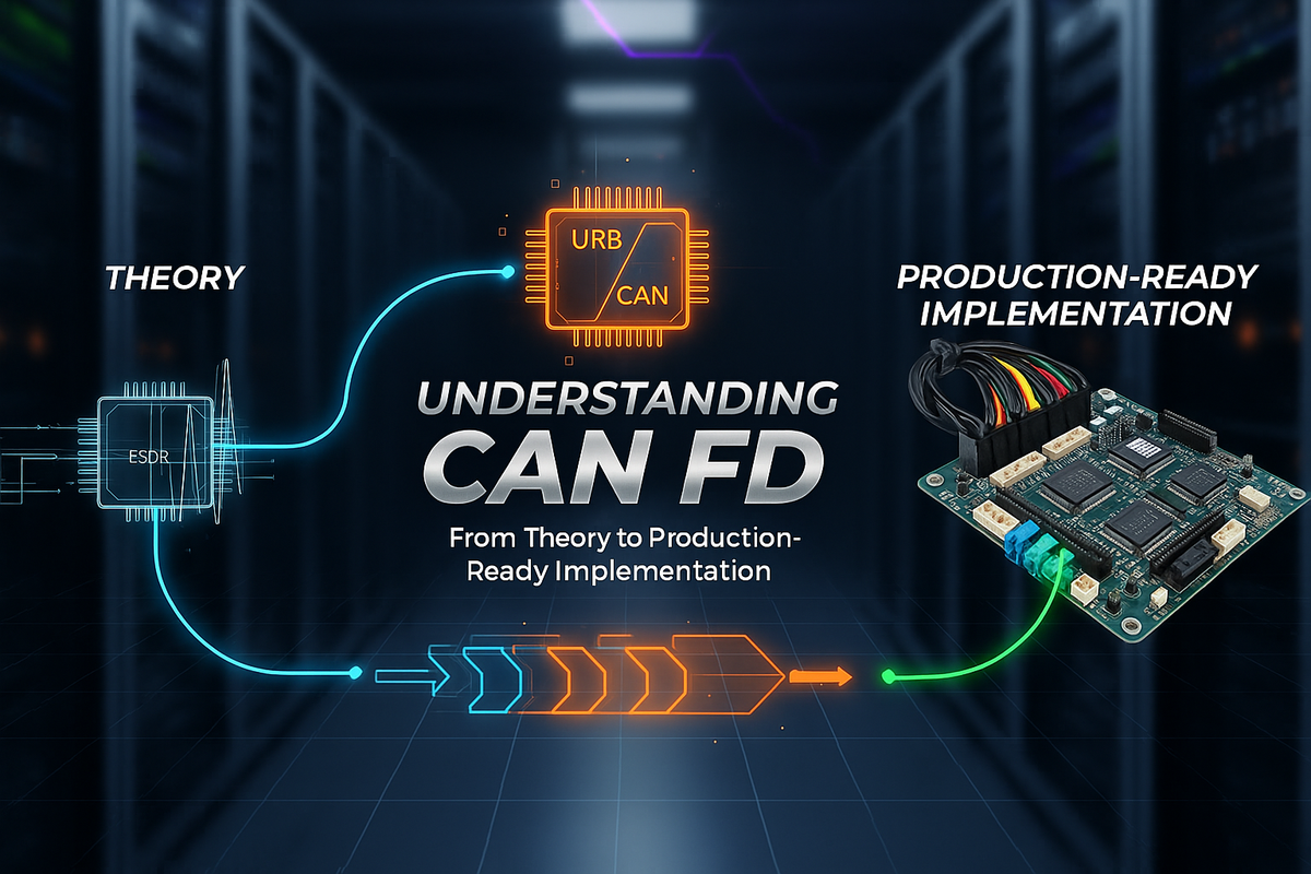
Understanding CAN FD: From Theory to Production-Ready Implementation
A guide to CAN controllers, transceivers, and bus configuration
When our team began developing IoT devices for a pet environment platform, we faced a critical challenge: transmitting high-resolution sensor data between multiple ECUs with microsecond-level timing precision. We needed CAN FD.
But CAN FD isn't just "CAN, but faster." The jump to 8 Mbit/s data rates and 64-byte payloads means understanding three interconnected layers: the CAN controller (protocol engine), the transceiver (physical layer interface), and the bus itself (differential signaling medium). Get one wrong and your bus won't work. Get all three right and you have a robust, deterministic communication backbone.
What is CAN FD?
CAN FD (Controller Area Network with Flexible Data-rate) evolves Classical CAN to overcome two major limits: payload size and bandwidth. Classical CAN caps out at 1 Mbit/s and 8-byte payloads with 15-bit CRC, leading to fragmented, high-latency communication. CAN FD reaches 8 Mbit/s with 64-byte payloads and up to 21-bit CRC, enabling atomic, low-latency communication.
Our platform uses CAN FD to stream camera metadata (timestamps, exposure settings, calibration data) alongside LiDAR point cloud summaries to a central fusion ECU. With CAN FD's 64-byte payload, that's a single atomic message, reducing latency and eliminating reassembly bugs. The real insight: CAN FD isn't about raw speed alone, it's about atomic message integrity and reduced bus arbitration overhead.
The three-layer stack
Controller bugs manifest as timing errors, incorrect CRC, or arbitration failures. Transceiver bugs manifest as no bus activity, thermal shutdowns, or mode control issues. Bus bugs manifest as reflections, impedance mismatches, or EMI-induced errors. Most debugging time gets spent at the boundaries: controller-to-transceiver timing, and transceiver-to-bus impedance matching.
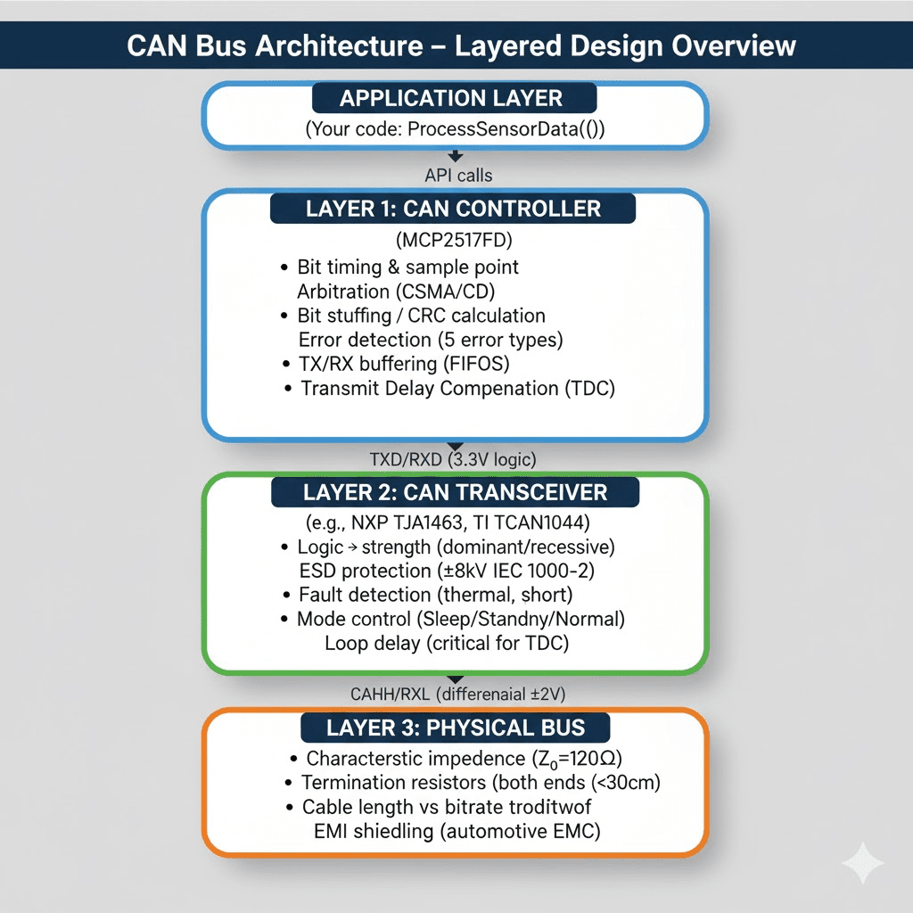
Layer 1: the CAN controller
The controller is a hardware state machine implementing ISO 11898-1:2015. Its core responsibilities: bit timing and sampling, dividing each bit into time quanta and defining the sample point (typically 75 to 87.5% of bit time), with Synchronization Jump Width adjusting phase; arbitration, monitoring the bus during transmission and losing gracefully when a dominant bit overwrites a recessive one; bit stuffing, inserting a complement bit after 5 consecutive identical bits to maintain clock sync; CRC calculation, using different polynomials and lengths depending on payload size, 17-bit CRC for payloads up to 16 bytes, 21-bit for larger; error detection covering bit errors, stuff errors, CRC errors, form errors, and ACK errors; and TX/RX buffering that decouples application timing from bus timing through FIFO or priority queues.
Every bit divides into Sync_Seg (always 1 time quantum), Prop_Seg (propagation delay), Phase_Seg1, Phase_Seg2, and SJW (max phase adjustment). Sample point percentage is (Sync_Seg + Prop_Seg + Phase_Seg1) / Total_bit_time x 100%. Design targets: 75 to 80% sample point for the nominal (arbitration) phase, 80 to 87.5% for the data phase, and an SJW of 1 to 2 time quanta for minor clock drift correction.
Transmit Delay Compensation. At bitrates above 2 Mbit/s, the transceiver loop delay (TXD to CANH/CANL to RXD) becomes significant relative to bit time. At 5 Mbit/s, a 200ns bit time against a typical 120ns transceiver delay means the delay eats 60% of the bit. If the controller samples RXD at the normal sample point, it's sampling its own delayed transmission instead of the actual bus state, causing false bit errors. TDC introduces a secondary sample point accounting for the loop delay. Measuring it: capture TXD and RXD on a dual-channel scope, transmit a test frame at the target bitrate, measure the edge delay, and convert to time quantum units. A measured 125ns loop delay against a 12.5ns time quantum period gives a TDC offset of 10 time quanta.
Layer 2: the CAN transceiver
The transceiver bridges digital and analog worlds: a differential driver converts TXD logic to the CANH/CANL differential pair (dominant bit at roughly +2V differential, recessive at 0V), a differential receiver converts that back to RXD logic with roughly plus-or-minus 0.9V thresholds for noise immunity, ESD protection guards against electrostatic discharge, fault detection covers thermal shutdown, short circuit, open load, and undervoltage lockout, and mode control spans sleep, standby, normal, and sometimes listen-only modes with very different current draws.
We chose the NXP TJA1463 for one of our modules because, unlike SPI-controlled transceivers, it uses simple GPIO pins for mode control: sleep at roughly 100 microamps, standby at roughly 5mA with RXD monitoring, normal at roughly 50mA for full TX/RX, and listen-only at roughly 5mA for bus monitoring. Listen-only mode sometimes needs additional controller filter configuration and dedicated startup hardware setup to avoid transmitting ACK signals during monitoring, it isn't always as simple as flipping GPIO pins.
Critical timing from the datasheet: startup needs over 1.5ms after power-up before the first mode change, mode transitions need under 50 microseconds, entering sleep needs over 24 microseconds with the right pin states, and the bus needs under 2 microseconds to settle after a mode change.
The most common transceiver issues we've hit: no bus activity despite a successful FDCAN transmit, usually a transceiver stuck in sleep or standby, verify EN and STB_N pin states for normal mode. A constantly-low ERR_N pin usually points to thermal shutdown or a short, check bus termination should read 60 ohms and consider a heat sink if junction temperature exceeds 125°C. Intermittent TX often comes from incomplete mode transitions, add 10ms delays after GPIO changes. High bit errors often trace to a VIO mismatch with the MCU, set the transceiver's VIO pin to match MCU I/O voltage. And bus-off after several minutes of operation often points to thermal drift in loop delay, enable transceiver signal improvement capability and verify the TDC filter window.
Why differential signaling. Data encoded as the voltage difference between CANH and CANL, not absolute levels, gives common-mode noise rejection (EMI and ground bounce affect both wires equally and cancel out in the differential receiver), no ground reference requirement (eliminating ground loop issues across multiple ECUs), and extended cable length (lower signal swing reduces EMI emissions, twisted pair cancels magnetic coupling, achieving roughly 40m at 1 Mbit/s or up to 1km at 50 kbit/s).
Layer 3: the bus as a transmission line
A CAN bus is a transmission line where signal propagation delay is significant relative to bit time. Without proper termination you get ringing, false bit detection, and reduced noise margins. Characteristic impedance for typical CAN twisted-pair cable works out to roughly 120 ohms. Termination needs a resistor equal to that impedance at both ends of the bus, not at every node, giving 60 ohms measured across CANH-CANL with two 120 ohm terminators in parallel. Verification: power off all ECUs, measure CANH-CANL resistance, expect 60 ohms plus-or-minus 5%, 120 ohms means a missing terminator, 40 ohms means an extra one, and an open circuit means no terminators or a broken bus.
Systematic debugging
"I send messages but nothing appears on the bus." Symptoms: TX successful flag set, but the scope shows no CANH/CANL activity, no errors reported. Most likely causes in order: transceiver stuck in sleep or standby (by far the most common), a VIO mismatch, disconnected TXD/RXD traces, or missing transceiver power.
"High bit error rate and bus-off states." Symptoms: CRC errors, a climbing transmit error counter, the controller entering bus-off. Most common causes: incorrect bit timing (sample point too early or late, missing TDC, clock frequency mismatch), termination problems (missing or extra terminator, wrong resistor value), cable too long for the bitrate, or EMI and noise coupling.
"Intermittent communication failures." Symptoms: works for minutes or hours then stops, random message loss, errors correlating with temperature or vibration. Most common causes: thermal issues (junction temperature exceeding limits, inadequate PCB copper or airflow), power supply problems (VCC drooping under load, insufficient bulk capacitance), connector intermittency (loose crimps, vibration-induced disconnects, corrosion), or EMI coupling from inadequate shielding.
Battle-tested lessons
Measure, don't trust the calculation. Clock sources have real tolerance (plus-or-minus 1 to 2% for crystal, 3 to 5% for RC oscillator), which affects bit timing accuracy. Verify the clock with a frequency counter, measure actual bit width on RXD with a fast scope, and calculate the percentage error, adjusting if it exceeds about 2%.
Transceiver mode control is critical. We spent two days debugging "no bus output" before discovering the transceiver was in standby mode despite correct FDCAN configuration, the controller can transmit perfectly, but nothing reaches the bus if the transceiver isn't in normal mode. Always verify GPIO states before blaming the controller, add diagnostic functions printing pin states, and use generous delays after mode changes since datasheet minimums don't always account for PCB parasitics.
Key takeaways
CAN FD requires understanding three interdependent layers: the controller for bit timing and error detection, the transceiver for mode control and physical interface, and the bus for impedance matching and termination. Measure, don't assume, verify bit timing with an oscilloscope. Mode control matters, the transceiver has to be in normal mode for transmission to reach the bus. DLC is non-linear above 8 bytes, use a lookup table. Layer boundaries hide bugs, monitor controller, transceiver, and bus independently. Test incrementally, loopback, then single node, then multi-node. TDC is mandatory above 2 Mbit/s. And use 50 to 70% of theoretical maximum bus length and bitrate in real deployments, not the datasheet ceiling.