

Antenna Tuning in Small Enclosures: Preserving Wireless Performance Under Real-World Constraints
Every Hoomanely product is conceived as a balanced system, firmware, electronics, mechanics, and user experience working in harmony. The enclosure is the part users touch and see first, but for wireless-enabled devices it plays an even deeper role. It silently shapes how the antenna inside behaves.
ABS housings, whether curved, rectangular, or organically sculpted, become part of the RF environment. They detune resonant frequencies, absorb and reflect energy, and alter radiation patterns. What looks like a small change in geometry can translate into large shifts in wireless performance. For this reason, antenna tuning is not a final checklist item, it's a mandatory engineering discipline.
As our devices shrink and integrate more features into compact forms like trackers, smart bowls, and hubs, the antenna increasingly lives in a difficult neighborhood. Small enclosures mean less freedom, tighter clearances, and more sensitivity to materials and surfaces.
The enclosure as an RF participant
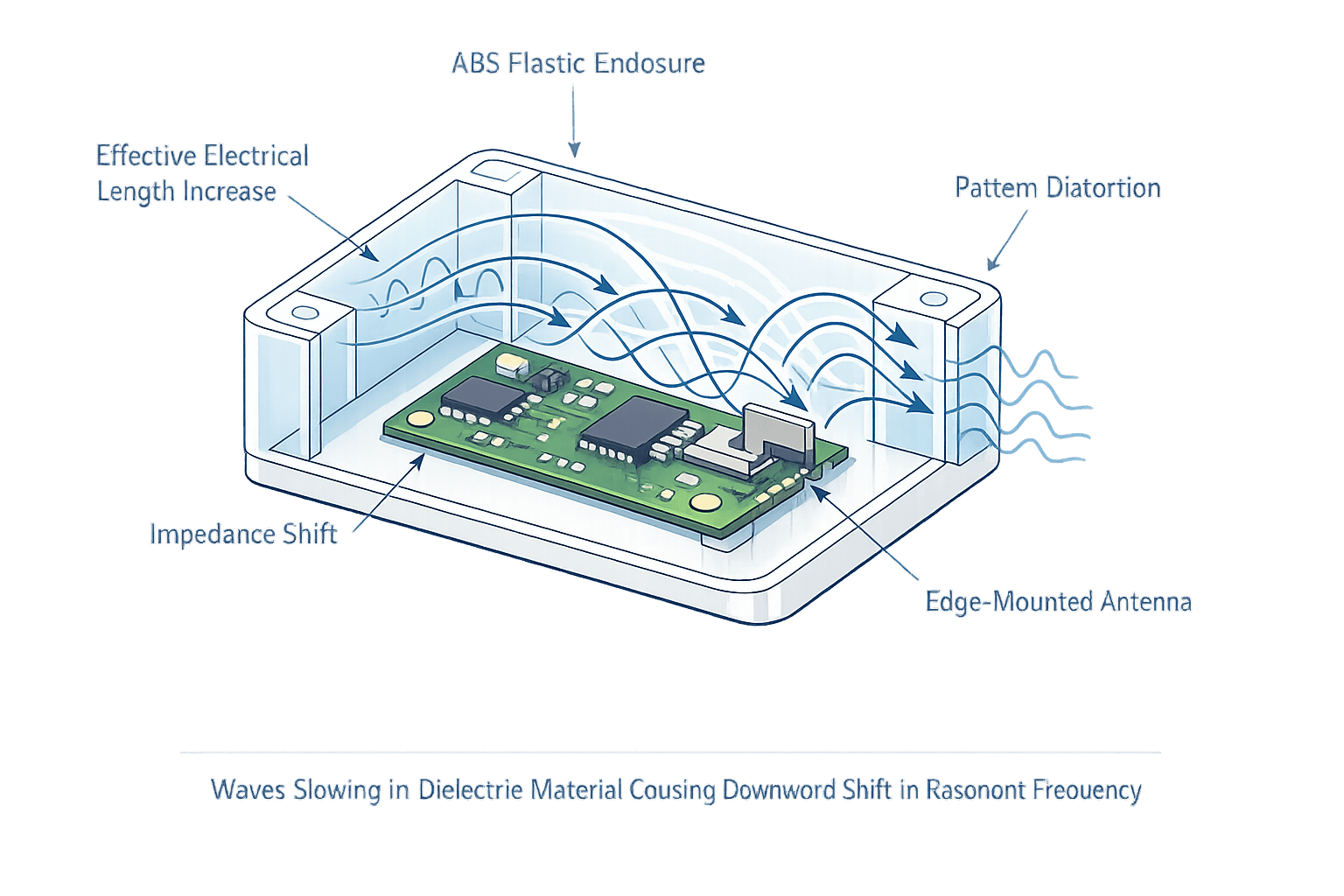
In textbooks, antennas are tuned in open air. In products, they never operate that way. The enclosure surrounds the antenna with dielectric material. ABS, with a relative permittivity typically between 2.5 and 3.0, slows electromagnetic waves and effectively increases the electrical length of the antenna.
Curved enclosures introduce non-uniform spacing between the antenna and plastic surface. The distance from antenna to wall may be 2mm at one point and 8mm at another. This varying dielectric loading creates unpredictable shifts in impedance and resonance. Rectangular enclosures can be equally challenging. Flat parallel walls behave like reflectors, promoting internal standing waves. Corners concentrate fields. Ribs and screw bosses add localized masses of plastic near critical RF regions.
Even the finish of the enclosure matters, paint, internal metallization, or decorative coatings can further disturb RF behavior. A plastic part, therefore, becomes an extension of the antenna system, sometimes helping, sometimes hurting, but always influencing. Each product variant, each enclosure revision, and sometimes even each colourway requires dedicated tuning so the final assembled unit meets the intended RF budget.
Why one-size-fits-all tuning doesn't work
Early in our journey, we might have imagined that tuning an antenna once would suffice across multiple products. Experience across a growing fleet has shown otherwise. The antenna inside an EverSense tracker or EverHub gateway sits at a unique location relative to plastic thickness, nearby batteries or metal rings, PCB ground planes, screws, wires, and other modules, and the exact shape of the ABS shell.
All of these combine into a custom RF ecosystem. Changing the enclosure from a simple flat lid to a curved ergonomic surface can shift the antenna's centre frequency by tens of megahertz, easily enough to move the device out of regulatory or functional range limits. Therefore, tuning must be performed in-situ, with the antenna mounted exactly as it will be in the product. The enclosure becomes part of the measurement, not an afterthought.
The physics of detuning
Understanding why tuning is required begins with the core RF variables. Antennas are typically designed for 50-ohm systems, and the ABS material near the antenna alters capacitance between the radiator and ground, changing the feed impedance. Without correction, return loss degrades and transmitted power reflects back into the radio chip.
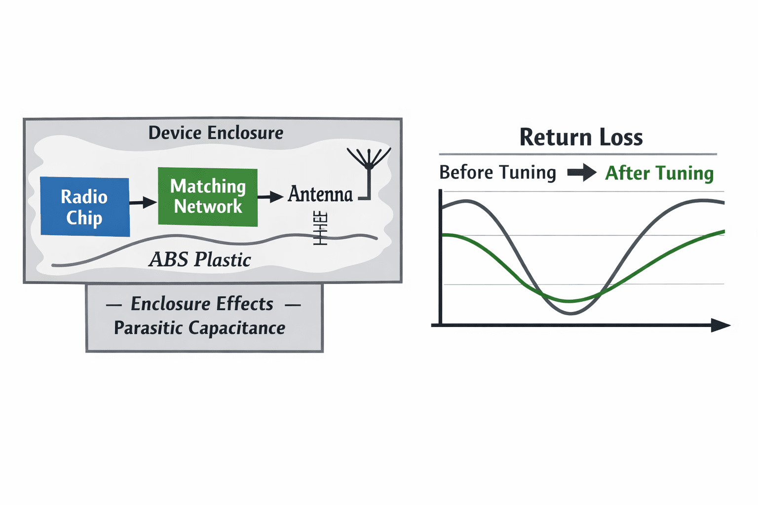
The dielectric constant of ABS effectively makes the antenna appear longer, pulling the resonant frequency downward. The amount of shift depends on how close the plastic is to the antenna and how much surface area loads it. Small enclosures force the antenna to coexist with many objects, batteries block fields, metal brackets reflect them, curved walls bend them. The pattern that was omnidirectional in free space may become directional or develop null zones. And ABS also has a loss tangent, some RF energy converts into heat inside the plastic instead of radiating outward, reducing overall antenna efficiency, particularly in ultra-small form factors.
These phenomena are unavoidable. But they're manageable, through systematic tuning and intelligent mechanical design.
Small enclosures: the toughest RF challenge
As devices reduce in size, the problem intensifies. Large routers or laptops provide generous antenna clearance. Our compact pet-care modules rarely do. In a tiny wearable enclosure, the antenna may have only a few millimeters of separation from walls and metal sub-parts.
Key limitations include no room for large radiating elements, restricted orientation choices, minimal PCB area for RF ground planes, close proximity to high-current power circuitry, and user-facing mechanical parts that cannot be moved easily. In these cases, tuning is essential to recover lost performance. The antenna must be carefully positioned and then adjusted electrically so that, despite cramped conditions, it delivers reliable connectivity.
Design constraints that guide tuning
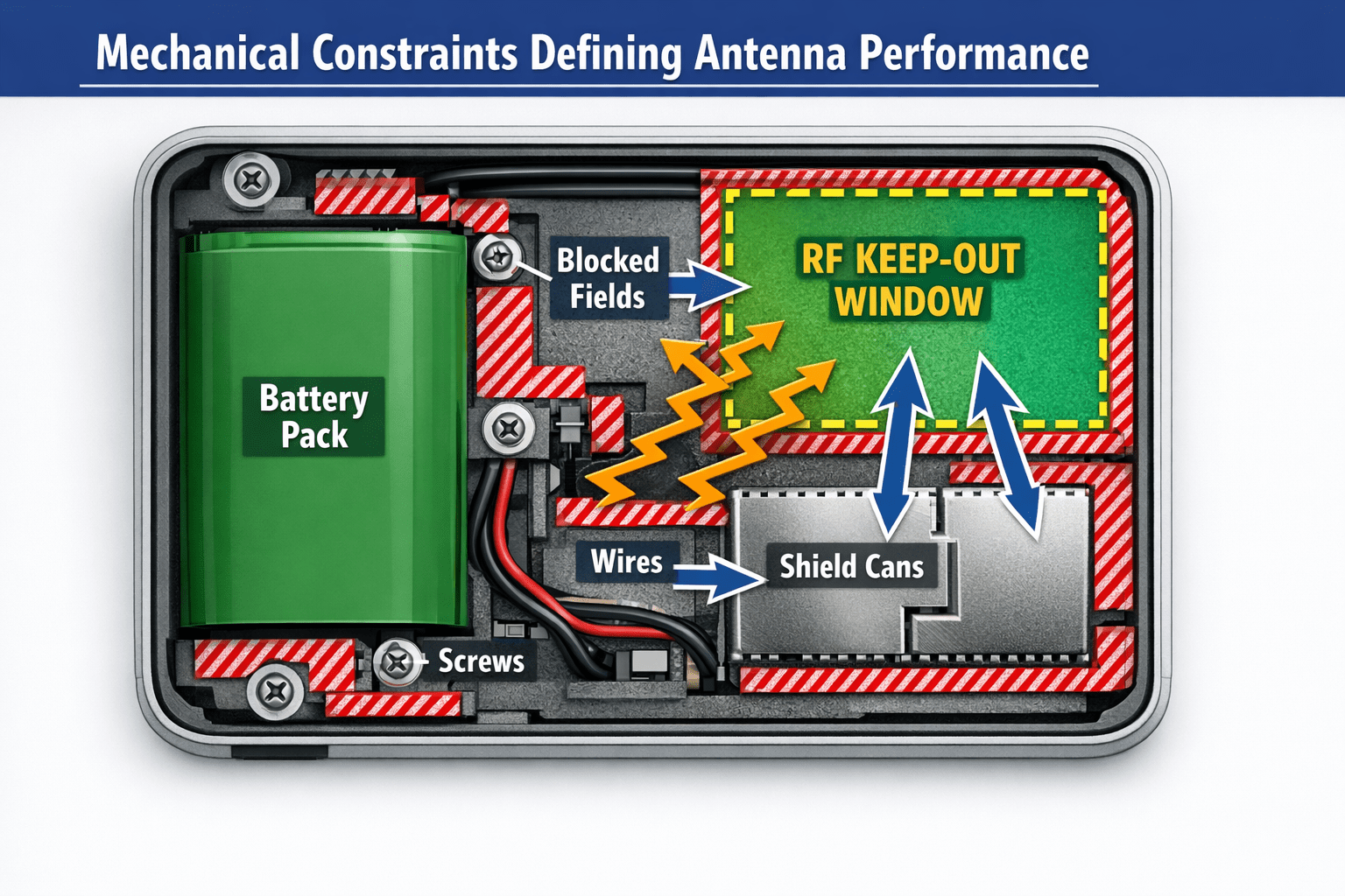
Before any tuning begins, several product-level variables must be defined clearly. Antenna location budget determines where the antenna can live, near the board edge, along an enclosure wall, around a metal ring, or embedded into a specific Peripheral SoM. Each choice impacts the available tuning range, so final location decisions must be frozen early.
Material thickness directly affects detuning, thin walls create a smaller shift, thick decorative regions create a larger shift, and multi-layer ABS plus rubber overmolds add significant RF loading. This dictates whether we adjust using matching networks, antenna geometry changes, or both.
Even in non-metallic enclosures, internal components introduce metal, stainless-steel rings in smart bowls, batteries, screws, shields, and USB-C connectors. Keep-out zones around the antenna become necessary, and these zones also determine how far tuning components can compensate.
Curved versus flat ABS surfaces change the effective dielectric interaction, cylindrical curvature may load the antenna unevenly, domed lids introduce higher capacitance, and internal ribs create localized detuning pockets. Tuning must therefore be performed with the final enclosure shape, not preliminary CAD approximations. And wireless devices must meet transmission power limits, spurious emission limits, and specific frequency bands, so proper tuning ensures detuning from plastic doesn't push us out of these legal envelopes.
The tools of in-situ antenna tuning
The kinds of tools involved in this science include vector network analysers that measure real impedance inside assembled units, S-parameter measurements that reveal how ABS surfaces affect resonance, matching networks on PCBs that allow electrical correction, and 3D mechanical previews that help visualize antenna-to-wall distances. These tools together convert RF uncertainty into quantifiable data.
Mechanical design as a tuning enabler
Good antenna performance in small enclosures is achieved not only by electrical tuning, but by deliberate mechanical empathy. We design enclosures to support RF needs:
- Antenna windows free of metal paint
- Uniform ABS thickness near the antenna
- Strategic standoff distances
- Proper connector placement away from RF zones
- Non-conductive fasteners where practical
- Avoiding unnecessary decorative ribs near antennas
These considerations ensure tuning adjustments remain within achievable range instead of fighting impossible physics.
The cost of not tuning
Skipping antenna tuning in compact wireless products results in predictable consequences:
- Poor range
- Dropped BLE or LoRa packets
- Higher current consumption due to retransmissions
- Failed certifications
- Customer dissatisfaction despite excellent firmware
The enclosure may look beautiful, but connectivity becomes unreliable. Tuning prevents this disconnect between appearance and performance.
Design evolution demands continuous tuning
As product designs evolve, antenna tuning must evolve with them. Every change can influence RF behavior, a new enclosure revision, a different ABS material blend, changed internal module arrangement, added sensors or cables, a new battery vendor, or alternate connectors. By treating the antenna as part of the overall system contract, we ensure electrical and mechanical revisions travel together rather than diverging.
Aging gracefully: antennas as long-lived contracts
Small enclosures make antennas fragile in behavior, not in construction. Once tuned correctly, they become reliable for years. Our philosophy centers on tuning early, tuning with the enclosure, retuning with every revision, and validating RF as rigorously as firmware. This mindset ensures that as Hoomanely products deploy globally into homes, parks, and apartments, their antennas operate confidently within real-world constraints.
Conclusion: excellence in the details
A wireless-enabled product succeeds only when invisible systems perform as well as visible ones. ABS curved and rectangular enclosures will always influence antennas inside them. The engineering answer is not to avoid these enclosures, but to master them through disciplined tuning.
In small enclosures especially, every millimeter matters, every material surface participates, and every product variant deserves dedicated RF attention. Antenna tuning therefore becomes the art and science that preserves connectivity, ensures portability across designs, and protects the promise we embed into every Hoomanely device. This is true systems thinking, where mechanical beauty and wireless performance coexist, validated by precise characterization. When done right, antennas are tuned for the product, the enclosure, and the real world. And that's how compact devices deliver uncompromised wireless excellence.



