
Building High-Speed Camera : Mastering MIPI CSI-2 Device
Imagine a pet healthcare system that can detect subtle changes in gait, spot early signs of skin conditions, monitor breathing patterns during sleep, or track behavioral changes signaling discomfort, all through intelligent vision processing happening at the edge. That's the convergence of high-speed embedded imaging, real-time AI inference, and thoughtful systems engineering.
Modern embedded vision platforms need more than megapixels and frame rates. They need seamless hardware-software integration, deterministic latency for real-time decisions, power efficiency for always-on monitoring, and drivers robust enough to never fail in production.
The MIPI CSI-2 interface with D-PHY multi-lane configuration has become the standard for connecting image sensors to application processors, supporting data rates well into multiple gigabits per second. But bridging the gap between a raw image sensor and actionable vision intelligence takes real understanding of physical layer protocols, kernel driver architecture, and the Linux Video4Linux2 framework.
Understanding MIPI CSI-2 beyond the marketing specs
CSI-2 isn't just a connector spec, it's a complete ecosystem of physical signaling, protocol layers, and power management states working together. It scales from single-lane configurations for basic imaging up to four-lane implementations delivering aggregate throughput well beyond 6 Gbps, with each lane operating independently and the protocol layer distributing and merging data dynamically.
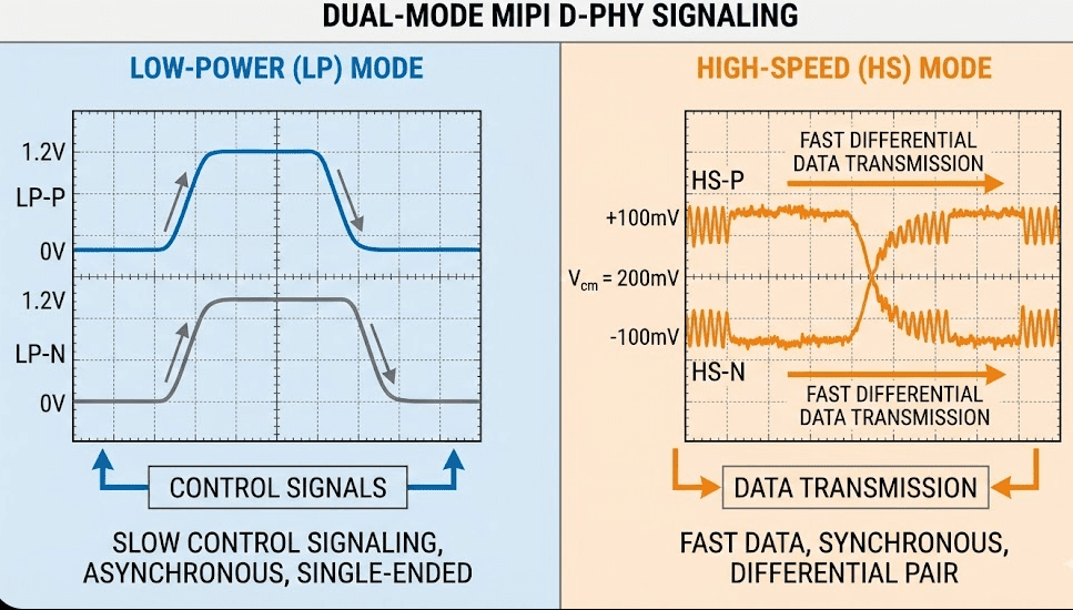
The D-PHY physical layer runs dual-mode: low-power mode for control and configuration using single-ended signaling, and high-speed mode for data transfer using low-voltage differential signaling that minimizes power while maximizing noise immunity. Unlike older parallel interfaces needing precise timing alignment across many signals, CSI-2's packet-based structure carries synchronization, data, and metadata self-contained, simplifying PCB routing and enabling longer cable runs with SerDes. A single physical interface can also multiplex up to 16 virtual channels, enabling multi-camera systems or separate image and metadata streams without extra physical connections, which matters a lot for applications needing visible light, thermal imaging, and depth sensing running simultaneously.
The physical layer: where silicon meets signal
Low-power mode operates at roughly 1.2V amplitude single-ended signaling, handling lane initialization, mode transitions, escape mode commands, and Ultra-Low Power State entry and exit. Data rates stay intentionally low, around 10 Mbps, because the larger voltage swings would consume too much power at higher frequencies. High-speed mode switches to differential signaling with much smaller swings, roughly plus-or-minus 200mV around a common-mode voltage, enabling multi-gigabit rates while keeping excellent noise rejection.
The transition between modes isn't instantaneous. The spec defines precise timing parameters, THS-Prepare, THS-Zero, THS-Trail, that determine how long the transmitter has to hold specific voltage levels during transitions. Getting these wrong causes synchronization failures that show up as corrupted frames or stream dropouts, and these aren't academic numbers, they get debugged with oscilloscopes at 2 GHz bandwidth showing eye diagrams at picosecond resolution. A manufacturing variation shifting timing by 100 picoseconds can move a system from "works perfectly" to "fails intermittently."
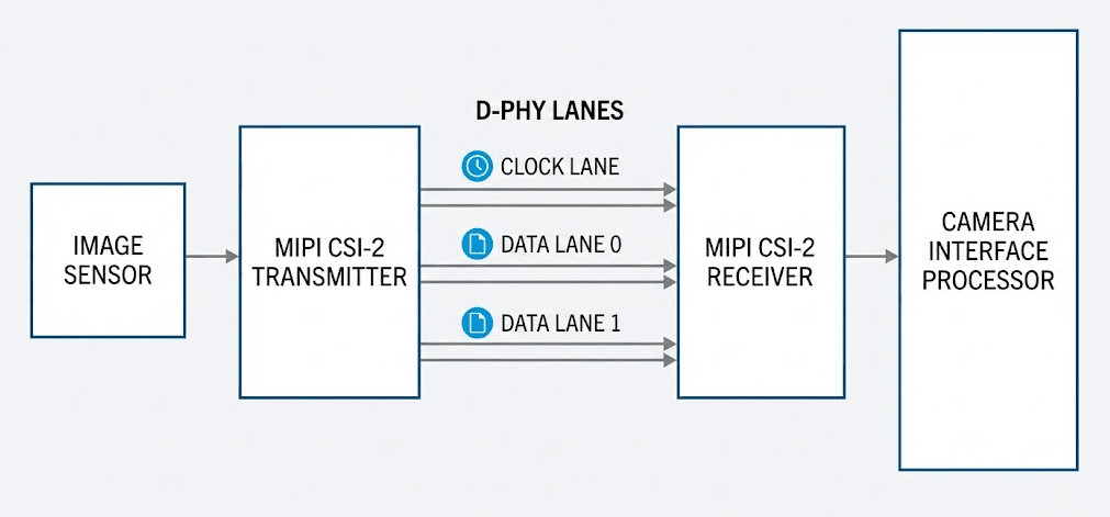
In multi-lane configurations, data distributes across lanes round-robin, with lane 0 always present and lanes 1-3 optional based on bandwidth needs. The clock lane can run continuous (always running, simpler receiver design, more power) or non-continuous (starts and stops with data bursts, needs more sophisticated clock recovery but enables deeper power savings between frames).
Protocol layers: structuring the data pipeline
At the top, your application, a computer vision pipeline, an ML model, a video encoder, doesn't concern itself with lanes or voltage swings, it just requests frames through Video4Linux2.
Below that, the pixel-to-byte layer packs sensor data efficiently. For RAW10 format, four pixels consume five bytes: each pixel contributes its 8 most significant bits as one byte, then all four pixels' 2 least significant bits pack into the fifth byte, maximizing dynamic range while minimizing bandwidth. Understanding this matters when your bandwidth calculations don't match observed throughput, those extra packing bytes add up across millions of pixels.
The low-level protocol layer structures data into short packets (header-only, used for Frame Start, Frame End, Line Start, and Line End synchronization, carrying virtual channel ID, data type, and a word count) and long packets (carrying actual pixel data or metadata, with a header, payload up to 65535 bytes, and a 16-bit CRC footer). A frame looks like a Frame Start, then repeating Line Start, pixel data, Line End blocks, then a Frame End. Any CRC mismatch typically discards the whole frame rather than delivering corrupted data.
The lane management layer distributes outgoing bytes across available lanes and merges incoming lanes back into one stream, at byte granularity in round-robin fashion. This isn't just about bandwidth, it's about flexibility, a system supporting four lanes can run in 1-lane mode for reduced power or 4-lane mode for maximum throughput with no hardware changes, which matters for product lines sharing common silicon across different imaging requirements.
Testing and validation
Bringing up a camera system follows a methodical process. Clock signal verification with an oscilloscope confirms the sensor clock is present at the correct frequency, missing or wrong clock is the number one cause of "sensor not responding" failures. I2C communication gets verified by reading the sensor's chip ID register, if that fails, nothing else will work. GPIO levels need confirming for reset and power-down pins, don't assume direction or polarity is correct. And power rails need measuring with the sensor powered on, verifying current consumption matches datasheet typical values.
Real-world application: pet healthcare vision
Our platform integrates multiple imaging modalities through this architecture. Behavioral analysis uses high-resolution visible-light imaging to capture subtle changes in movement, posture, and activity that signal discomfort or illness before other symptoms appear. Thermal monitoring provides non-contact temperature tracking, catching fever or localized inflammation. Depth sensing through time-of-flight or structured light enables precise gait analysis, identifying lameness or coordination issues with millimeter accuracy. And infrared illumination and sensitivity enable round-the-clock monitoring without disturbing sleep cycles.
All these sensors stream simultaneously through virtual channels in our CSI-2 implementation, processed by edge AI running on the embedded processor. Our biosense AI engine analyzes video in real time: behavior recognition detects normal versus abnormal patterns like excessive scratching or reduced activity, posture analysis identifies subtle changes in how pets stand, walk, or rest, breathing rate monitoring reads chest movement for continuous respiratory rate with no wearables, and skin condition detection combines high-resolution imaging with ML to identify hot spots or irritations needing veterinary attention.
Key takeaways
MIPI CSI-2 with D-PHY gives scalable, power-efficient camera connectivity from mobile devices to industrial systems to pet healthcare platforms. Understanding physical layer operation, LP and HS modes, timing parameters, lane synchronization, is essential for debugging production issues beyond simple integration. The layered protocol architecture, physical signaling, lane management, packet structure, application interface, separates concerns and enables modular driver development. And real applications like this pet healthcare platform show how robust camera integration enables continuous monitoring and preventive care through edge AI and multi-sensor fusion.



