
Design Rules That Work: PCB DRC at Scale in the vBus Ecosystem
At Hoomanely, Design Rule Checking isn't a bureaucratic hurdle, it's an intelligent validation layer that catches real manufacturing issues while keeping design velocity high. As our vBus product portfolio has grown, we've refined our DRC philosophy: rules must catch genuine problems that would cause manufacturing failures, while never blocking progress on valid design decisions.
Manufacturing-driven rules
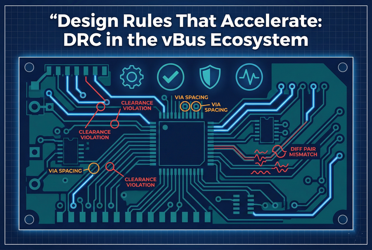
Our DRC rules directly reflect PCB manufacturer capabilities, every rule ties to a specific constraint. Trace width and spacing: a minimum trace width of 6 mil (0.15mm), 20% above the manufacturer's 5 mil minimum for process margin; minimum clearance of 6 mil standard, 20 mil for high-voltage signals; power traces sized per IPC-2221 based on current requirements. Via specifications:
- Minimum 8 mil finished drill
- Minimum 4 mil annular ring
- Via-in-pad flagged for review since it requires special manufacturing
High-speed signal rules:
- Differential pairs matched to within ±10% width and 5 mil length
- Return path verification requiring a continuous ground plane under signals
- Via stubs flagged when exceeding 20 mil
Component placement: 50 mil minimum to board edge, 20 mil minimum between components, 100 mil clearance to mounting holes. None of these are theoretical, they're validated against actual manufacturing process data from our fabrication partners.
vBus-specific design rules
DRC scripts automatically validate connector pin-out against vBus standards, power pins positioned correctly, signal pins matching specification, ground pins maintaining a 1:1 ratio with power pins. Automated checks enforce signal naming conventions, power nets in a voltage-type-domain format, signal nets in an interface-signal-destination format, control signals in a function-type-target format, with non-compliant names flagged along with correction suggestions.
Module-specific rules layer on top. CPU SoM requirements include DDR routing length matching (±5 mil for address and command, ±25 mil for data), decoupling capacitors within 200 mil of power pins, and a minimum of 30 thermal vias under processors. Power SoM requirements validate high-current trace widths against actual requirements, thermal vias under switching regulators and MOSFETs, and component placement per datasheet guidelines. Peripheral SoM requirements include guard rings around high-impedance analog signals, I2C pull-up resistor verification, and interrupt traces routed to interrupt-capable pins. Communication SoM requirements enforce 50-ohm controlled impedance RF traces, antenna keep-out zones, and EMI shielding and grounding verification.
DRC execution framework
Modern EDA tools provide real-time checking, violations appear as the designer works, preventing error accumulation and allowing corrections during routing rather than after. Batch validation runs a full comprehensive check before review or manufacturing, producing a detailed report with violation count per category, specific locations, severity classification, and resolution suggestions.
Design review integration requires zero DRC errors before scheduling a review, so reviewers focus on design intent, not basic violations, while non-critical warnings get reviewed in the meeting to distinguish justified design decisions from actual concerns.
Rule tuning and evolution
First-pass yield gets tracked per design, high yield validates the rules, lower yield triggers investigation into whether violations were missed, whether rules need adjustment, or whether new failure modes were discovered. When manufacturing issues occur, DRC gets updated to catch similar problems in future designs. As manufacturing capabilities improve, rules evolve too, tighter tolerances enable higher density designs, new processes require rule updates, and enhanced capabilities get reflected in relaxed constraints where appropriate. Designer feedback catches false positives for adjustment, missing checks get added based on field experience, and rule clarity improves based on usage patterns.
Production timeline benefits
Every PCB re-spin costs 5-9 weeks plus financial impact. Our above-95% first-pass success rate means most designs work correctly on the first manufactured revision, DRC catches issues before fabrication. Pre-cleared DRC lets reviewers focus on architectural decisions, signal integrity optimization, component selection strategy, and thermal management, completing design reviews 30-40% faster when mechanical violations are pre-cleared.
Consistent DRC adherence builds fabricator trust too, designs known to meet capabilities mean reduced pre-production questions, faster quotes and turnaround, and occasional priority scheduling access. And vBus modularity allows simultaneous module development, DRC standardization ensures integration success, connector pinouts validated, signal naming consistent, no mechanical interference, letting teams design CPU, Power, and Peripheral SoMs in parallel with confidence that DRC-validated designs integrate on first assembly.
Key performance metrics
First-pass success rate runs above 95% of designs manufactured successfully on the first revision. Design review efficiency improves 30-40% when DRC pre-validates. Rule hit analysis tracks which rules trigger most, identifying training needs and rule tuning opportunities. Time to clean DRC gets monitored per designer and project, indicating design complexity and training effectiveness.
Conclusion: quality at speed
PCB DRC at scale is intelligent automation that catches real issues while maintaining design velocity. Our approach, manufacturing-driven rules, continuous validation, feedback-driven tuning, ensures DRC serves as a quality multiplier.
The results:
- Above-95% first-pass success
- Faster design reviews
- Eliminated manufacturing delays
- Confident parallel development across our vBus portfolio
DRC isn't overhead, it's infrastructure enabling us to design better products faster. As our ecosystem grows, our DRC framework evolves with it, new modules adopt established rules immediately, manufacturing feedback refines rules continuously, and automation handles mechanical verification, freeing engineers for innovation.



