
Designing for Light Pipes: Turning Photons into Product Experience
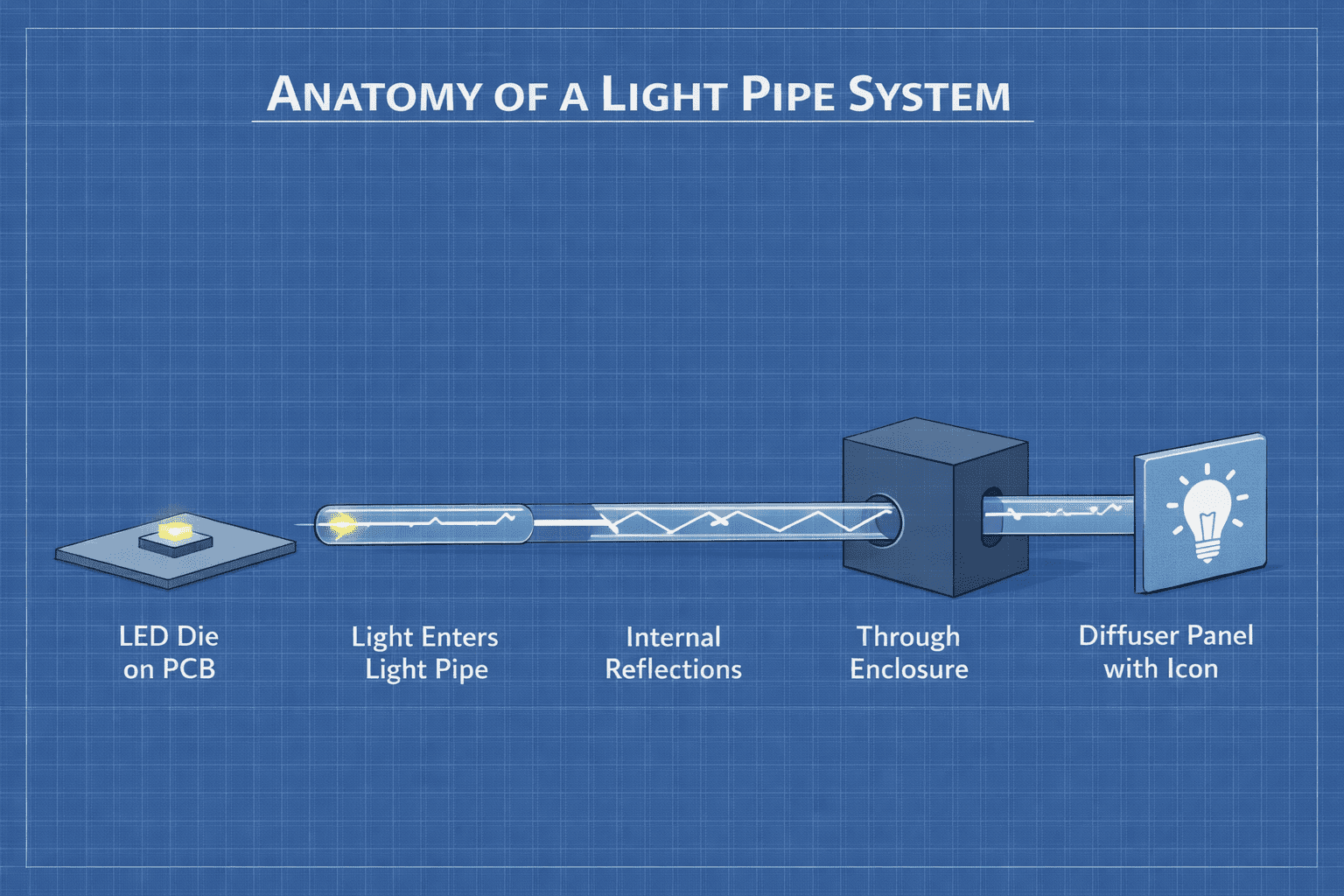
A glowing icon on a device seems simple. Behind that glow lies a compact mechanical channel guiding light from an LED to the user's eye. At product scale, this channel, the light pipe, becomes one of the most human-facing components in the entire design. It must translate raw electrical energy into precise optical output while fitting comfortably within tight enclosure envelopes.
Light pipes sit at the intersection of several constraints:
- LED placement on a PCB
- Enclosure tolerances
- Material choices
- Optical budgets
In vBus modular products, where sub-parts are independently engineered, these interfaces grow even more important. Every module may be designed by a different engineer, yet the light pipe must behave identically across all of them.
Why light pipes matter
From a commercial and usability standpoint, illumination is often the first functional cue that a product is alive. Whether it's a smart bowl module, a gateway hub, or a sensor node, the user depends on light for power state indication, communication activity, alerts and errors, and aesthetic brand identity.
Unlike software features that live inside code, light pipes are literal windows into the product. Their effectiveness directly influences legibility in bright rooms, visibility from multiple viewing angles, perceived quality of the enclosure, and assembly repeatability. A poorly designed light system can appear dim, misaligned, or inconsistent. A well-engineered one delivers confidence with every press of the button.
The anatomy of a light pipe system
At its core, a light pipe performs three jobs:
- Collect light from an LED source
- Transmit it efficiently through a mechanical medium
- Deliver it to the exterior surface without loss or distortion
But in real products, the "system" includes far more, the LED as electrical source, PCB location as mechanical origin, light pipe material, pipe geometry, enclosure opening, diffuser or icon, and the human eye as the final detector. Each of these stages must be engineered together.
Optical budgets: engineering the brightness
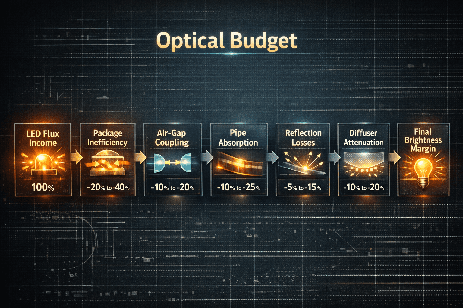
Every LED emits a fixed luminous flux. That flux is our optical income. The journey from LED die to enclosure face consumes portions of this income at each stage, LED package inefficiency, air gap coupling losses, light pipe absorption, reflection losses, and diffuser attenuation. At Hoomanely, optical budgets are built with the same seriousness as power trees. The objective is clear: maximize the transmitted light while staying within acceptable electrical power limits and thermal considerations.
To hit the right balance, engineers tune several variables: LED brightness selection, with higher mcd ratings for indicators meant to be viewed from distance; material transparency, polycarbonate or acrylic light guides with high optical clarity; diffuser choice, thinner diffusers for icons requiring brightness, heavier diffusers for aesthetic uniformity; and geometry efficiency, shorter pipes with fewer bends for power indicators. The key principle: the required brightness at the enclosure face should be achievable with a deliberate margin, typically 30 to 40% above minimum acceptable visibility, so variations in components and environments don't push the product into a dim or unreadable state.
Geometry: the path of light
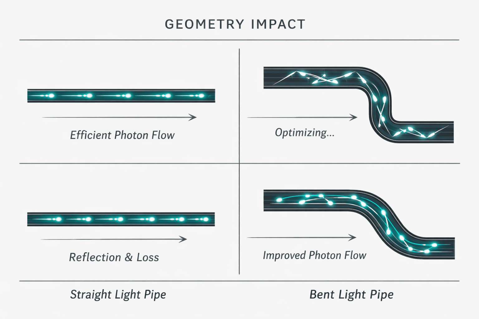
Geometry is where mechanical design becomes the hero. Straight light pipes offer best efficiency and are preferred for simple power LEDs. Bent or multi-segment pipes get used when enclosure constraints prevent direct alignment. Each bend introduces reflection inefficiency, so our designs include smooth radii bends, polished internal surfaces, reflective coatings when necessary, and strategic mirroring of LEDs closer to enclosure walls. When geometry becomes complex, LED placement is revisited rather than forcing the pipe itself to compensate.
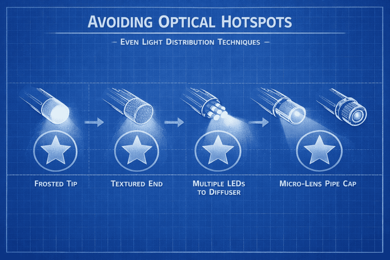
Uniform illumination matters for icons and front panels. Techniques include frosted pipe tips, textured ends, multiple LEDs feeding one diffuser, and micro-lens structures. For multi-module systems like vBus, consistency across boards demands identical LED and pipe geometries.
Enclosure tolerances: designing for alignment reality
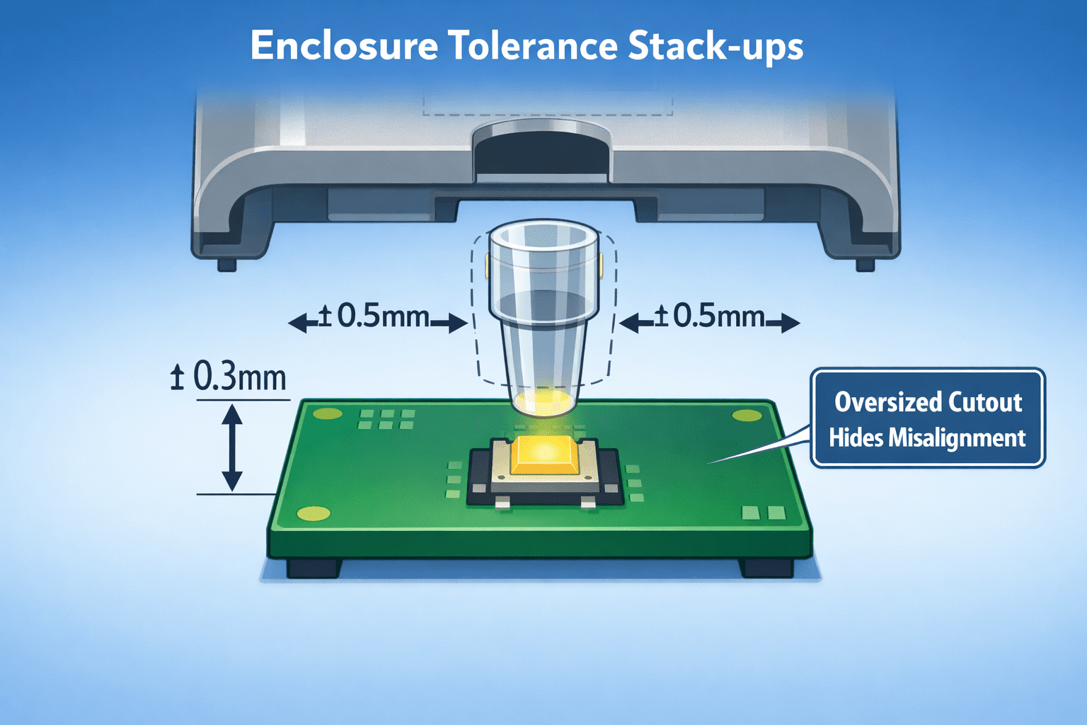
The light pipe doesn't live alone, it must pass through a precisely cut opening in the product enclosure. This is where tolerance stack-ups can disrupt optical alignment. Common constraints include PCB placement tolerance around ±0.3mm, enclosure cutout tolerance around ±0.5mm, connector alignment shifts, and assembly screw boss variations. These may seem small, but for a pipe delivering to a 3mm opening, they're enormous.
To handle this, our designs include self-aligning light pipe housings that guide the pipe directly onto LED center after enclosure closure, floating or compliant pipe mounts allowing minor lateral shifts without visible misalignment, asymmetric shells that mechanically force correct orientation, and silicone gaskets around pipe interfaces to maintain both optical and moisture integrity. Designers assume the enclosure will vary, so the opening on the enclosure is always designed larger than the pipe tip with a controlled shadowing zone, keeping misalignment invisible to users. vBus connectors often anchor PCBs at known positions, so we ensure pipe tip alignment considers connector datum, avoid pipes in zones of mechanical stress, and place LEDs near rigid anchoring points.
Material choices: the optical transmission medium
Light pipes are made primarily from acrylic (PMMA), polycarbonate (PC), or clear ABS, each bringing different characteristics across transparency, impact resistance, heat tolerance, moisture absorption, and rework ease. For consumer environments, polycarbonate becomes the preferred choice because it balances clarity with mechanical robustness.
Material must also survive heat from LEDs, heat-resistant plastics prevent discoloration, shorter pipes reduce exposure, and black masking paint around LEDs prevents light bleed into unintended regions.
PCB considerations: where electronics serve optics
Several PCB-level considerations remain central:
- LED orientation must be standardized
- LEDs placed at predictable datum points
- Avoiding vias or tall components between LED and pipe
- Using high-contrast soldermask under diffusers to avoid reflection artefacts
This allows every PCB variant to integrate seamlessly with identical light pipes.
Design validation: optical characterization
Optical validation ensures design intent is met through light meter readings at the enclosure face, angular visibility testing, bright room versus dark room characterization, and thermal drift visibility as the LED and pipe warm under temperature rise. The goal is not just "does it light up?" but whether the optical budget is maintained across all mechanical and environmental conditions.
Multi-angle UX: designing for human perception
Light pipes must serve human eyes in real environments, at viewing distances from 30cm to 3 meters, angles of view from 0 to 75 degrees, legibility under glare, and consistency across product SKUs. We design for daytime legibility, nighttime softness, color uniformity, and graceful alerts. This makes illumination both reliable and delightful.
Manufacturing jigs: enabling optical consistency
Jigs also play a crucial role, test jigs ensure LED positions are precise, enclosure jigs hold openings consistently, and assembly jigs prevent stress on pipes during closure. These processes ensure every assembled board presents an identical optical output to the user.
Where geometry fights light bleed
When multiple LEDs exist on a board, dedicated internal chambers, pipe-to-LED guard walls, black conformal masking zones, and diffuser partitions prevent photons from straying into unintended icons or windows.
Aging and aesthetics
Longevity concerns include pipe discoloration, scratches on diffuser surfaces, and LED brightness aging. By designing pipes as replaceable sub-parts, aesthetic refresh becomes possible on new revisions.
Cost considerations: balancing electrical, mechanical, optical
Engineers balance LED cost versus pipe efficiency, diffuser thickness versus brightness, and enclosure machining versus compliance. Small investments in optics reduce large costs in rework and support.
Conclusion: guiding light, guiding confidence
Light pipes are modest components with enormous impact. They deliver more than illumination, they deliver confidence, clarity, and first impressions. Designing them demands thoughtful attention to budgets, geometry, materials, and tolerances.
At Hoomanely, we've elevated light pipe design to first-class discipline. Every module we ship demonstrates that intuitive interaction backed by rigorous optical-mechanical engineering creates products that feel reliable and look delightful simultaneously. When electrons, plastics, and photons are engineered together, the glow users see is more than a light, it's the visible proof of design quality.



