
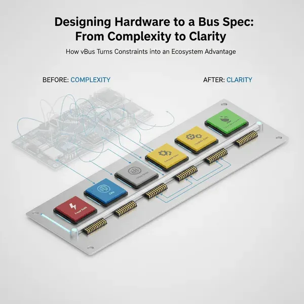
Designing Hardware to a Bus Spec: From Complexity to Clarity
There's a moment in every ambitious engineering project where you step back and think, "What have we gotten ourselves into?" For me, that moment came when we committed to designing all Hoomanely products around the vBus architecture. Not just one product, not just one product line, everything.
The challenge seemed daunting: how do you design diverse hardware, from industrial gateways to battery-powered sensors to robotic controllers, all conforming to the same rigid connector and communication standard? Here's the surprising truth I discovered: designing to a specification is actually liberating, not limiting. What initially felt like handcuffs turned out to be guardrails that guided us toward better, faster, more coherent designs.
The fundamental shift: products to ecosystems
Traditional hardware development identifies a market need, designs a complete product around it, optimizes for cost and performance, and ships it. Each product is self-contained. We've flipped that paradigm entirely, we don't design products, we design ecosystem participants. Every piece of hardware is conceived from day one as a module that will live within the vBus ecosystem, which means asking different questions during design: instead of "what does this product need to do," we ask "what role does this module play in the system"; instead of "how do we connect these components," we ask "which vBus connector blocks does this module require"; instead of "can we add this feature," we ask "does this feature fit within our pin budget and power envelope."
The building blocks: a modular formula
Through iteration, we've converged on a standard product architecture:
- A Peripheral SoM or SoMs doing the actual sensing or actuation work
- A Power SoM as the energy source and distribution hub
- A Carrier PCB as the motherboard physically and electrically connecting everything
- A Communication SoM as the gateway to external networks
Think of it as a hardware grammar, subjects, verbs, and objects that can be arranged into infinite sentences while following consistent rules.
This structure works because of clear separation of concerns, each module type has a focused purpose, making each simpler to design and test. It enables parallel development, different teams work on different modules simultaneously, confident their modules will work together because vBus defines the interface. It reduces risk, since modules with defined interfaces can be breadboarded and tested independently before system integration. And it optimizes inventory, manufacturing can stock a library of validated modules and quickly assemble various product configurations without custom PCB runs for each variant.
The classification system: variations on a theme
Early on, we hit an interesting problem. A robotics product needing 24V at 10A has vastly different requirements than a wearable running on 3.7V at 200mA. Do we create two completely different standards? That defeats the purpose. Our solution was classification hierarchies, each SoM family has multiple classes with different capabilities but identical connector pinouts and communication protocols.
Power SoMs illustrate this well. Class 1, high power and high voltage, targets industrial equipment and robotics with 5-24V input and multiple amp-level outputs. Class 2, medium power and standard voltage, targets general embedded systems with USB-C negotiation and battery charging. Class 3, low power and battery-optimized, targets wearables with ultra-low quiescent current and fuel gauge support. Class 4, high voltage and low current, targets PoE and industrial sensors with galvanic isolation and surge protection.
From the Carrier PCB's perspective, all Power SoMs look identical, the pinout is the same, the enable signal works the same way, the I2C status protocol is identical. The Carrier doesn't need to know which class is installed, it just works. This means a single Carrier design can support multiple power configurations, products can be up-specced or down-specced by swapping classes, field upgrades are possible without redesigning the system, and development teams can prototype with an easy-to-source class and deploy with a ruggedized one.
The same strategy applies across Peripheral SoMs (basic sensors, motion and inertial, vision modules, industrial I/O, actuator controllers), Communication SoMs (short-range wireless, WiFi and local networking, cellular, long-range low-power, industrial protocols), and CPU SoMs (microcontroller-based, basic application processor, performance application processor, high-performance with acceleration, FPGA-integrated). Each class addresses specific performance points while maintaining interface compatibility within its family.
Design process: from concept to vBus compliance
Consider a real example, an industrial environmental monitoring system requiring temperature, humidity, and air quality monitoring, 4-20mA outputs for HVAC integration, Modbus RTU with building management systems, and PoE power. Rather than designing a custom PCB with everything integrated, we broke it into modules:
- A Power SoM Class 4 for PoE input
- A Peripheral SoM Class 1 for environmental sensors and a Class 4 for isolated 4-20mA industrial I/O
- A Communication SoM Class 5 for Modbus RTU
- A CPU SoM Class 2 for basic Linux logging
Design within constraints means every module respects its pin budget, for example an environmental sensor Peripheral SoM on a 40-pin connector allocates 8 pins for standard power, 6 for the full communication block, 8 for the programming block, 1 for status, 1 for enable, leaving 16 for module-specific functions. This pin budget exercise happens before schematic design, a forcing function that eliminates scope creep and ensures compatibility. It also honors communication protocols, sensor data flows over FDCAN while configuration happens via I2C, with an onboard MCU translating a sensor's native interface into standardized CAN messages so the CPU SoM never needs to know sensor-specific details. And it maintains power discipline and implements every standard block, Power, Status, Enable, Communication, Programming, with no "we don't need that for this application" exceptions.
The Carrier PCB is where product-specific magic happens, but remarkably straightforward, place connectors per vBus spec, route power in a star topology, connect communication block signals, add external interfaces like terminal blocks and RJ45, include mounting features for the enclosure. Because SoM interfaces are standardized, most routing follows proven patterns, and Carrier PCB templates for common configurations can be adapted in days rather than weeks.
Validation happens at the module level first, power load testing and PoE compliance, sensor calibration and CAN message formatting, industrial I/O accuracy and isolation testing, Modbus protocol compliance, CPU boot sequence and application software. System integration, because interfaces are known-good, is often anticlimactic, it just works, minimizing time spent troubleshooting interface issues and maximizing time on application logic. Regression testing benefits too, when we update one module, we can test it with existing carriers and other modules, interface compatibility is guaranteed by vBus compliance.
The "aha" moment: when complexity becomes simplicity
Constraints breed creativity within boundaries. When you remove the decision paralysis of "how should we connect these components" and replace it with "we connect via vBus," you free mental bandwidth for the problems that actually matter, sensor performance, power architecture, firmware robustness. It's the same reason professional chefs prefer working within ingredient constraints, or why a character limit forces clearer writing.
Beyond the obvious advantages, we've discovered unexpected benefits. Product flexibility lets customers configure products to their needs, a basic environmental monitor becomes an advanced multi-sensor system by adding more Peripheral SoMs, letting us offer tiers without maintaining completely different hardware platforms. Incremental improvement means a better Class 1 Peripheral SoM benefits all existing products using that class, we can offer upgrade paths and our whole product line improves. Knowledge transfer accelerates since new engineers learn vBus once and apply it everywhere, documentation and debugging techniques are reusable. Supply chain resilience improves since if a component on a Power SoM goes end-of-life, we redesign just that module, unaffected products need only a module swap, no cascading redesigns. And rapid product development means we can often respond to new market opportunities in weeks by composing existing modules with a new Carrier design.
Design philosophy: three principles
"vBus first, features second" means when evaluating a new product idea, we start by asking how it fits into vBus, not what features we want. During planning for a multi-channel data logger needing 8 analog inputs, our first question wasn't which ADC to use but whether this needed a new Peripheral SoM class or could extend an existing one, we determined an existing class could accommodate it with a variant emphasizing analog capability.
"Classify, don't customize" means whenever a requirement seems unique, we resist creating a one-off custom module and instead ask whether it's unique enough to justify a new class. This prevents classification explosion while still providing flexibility for diverse applications.
"The Carrier is the canvas" means SoMs are the paint colors, the Carrier PCB is where artistry happens. We keep SoMs as generic and reusable as possible, pushing product-specific features, unusual connectors, custom mechanical interfaces, weird voltage translators, to the Carrier board. This keeps the module library clean and focused while still enabling infinite product variations.
Real-world impact: the numbers
After two years of vBus-disciplined design, time to market dropped 40-60% for new products leveraging existing modules, design iterations dropped from an average of 3 revisions to 1.5, cross-product part commonality reached 65%, manufacturing setup time dropped 50%, field service efficiency improved 70% through module swapping, and we launched 12 product variants in 18 months using module combinations. But the most compelling evidence is qualitative, engineering teams who initially resisted the constraints now actively evangelize the approach.
Conclusion: embrace the spec
Designing hardware to a bus specification, truly committing to it, is one of the most powerful architectural decisions we've made at Hoomanely. What looked like complexity was actually the path to simplicity, what felt like constraints were actually accelerators. We've moved from "design each product from scratch" to "compose products from validated modules," resulting in faster, more reliable, more maintainable hardware that scales from prototypes to production without the typical redesign pain.
My advice for product companies considering a modular architecture: commit fully. Half-measures, mostly following the spec except for a few convenient shortcuts, undermine the entire value proposition. The spec isn't the boss, the spec is the foundation. And on a solid foundation, you can build anything.



