
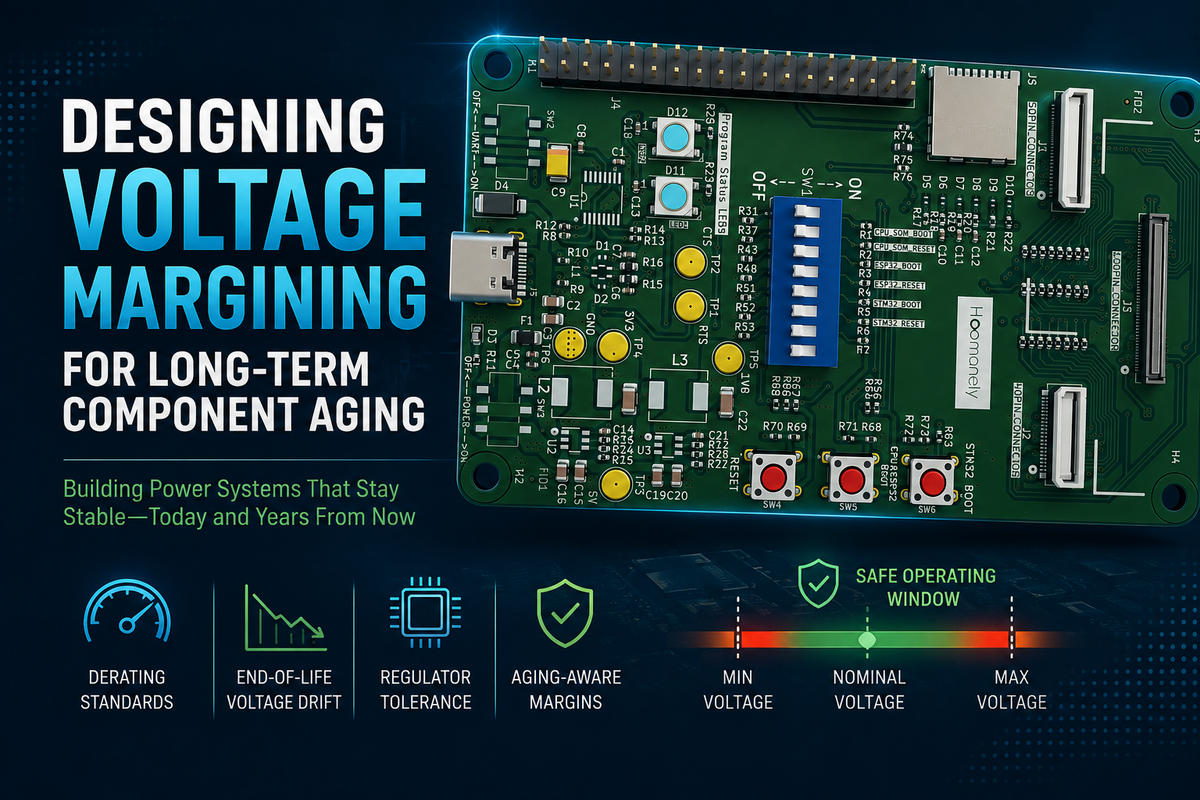
Designing Voltage Margining for Long-Term Component Aging
Building Hardware That Remains Stable After Years of Real-World Operation
In early hardware validation, voltage rails usually look perfect.
The regulator output is measured at room temperature. The load is controlled. The board passes functional tests. The oscilloscope shows clean waveforms.
Then the product spends three years in the field.
The regulator has aged. Capacitors have changed characteristics. Semiconductor thresholds have shifted. Thermal cycles have stressed components. The input supply is no longer as stable as it was during validation.
Suddenly, a system that was designed with a "correct" voltage becomes a system operating with reduced margin.
At Hoomanely, voltage design is not treated as selecting a regulator that provides the required voltage today. A power rail is considered a long-term operating environment where every component introduces tolerance, drift, temperature dependency, and aging effects.
The question is not:
"Can this circuit operate at 3.3V?"
The real engineering question is:
"Can this circuit still operate correctly when that 3.3V rail becomes 3.18V or 3.38V after years of real operation?"
Designing voltage margining is about answering that question before the product reaches customers.
Voltage Is Not a Fixed Number
One of the common mistakes in hardware design is treating regulator output voltage as a constant value.
A schematic may say:
3.3V Digital Rail
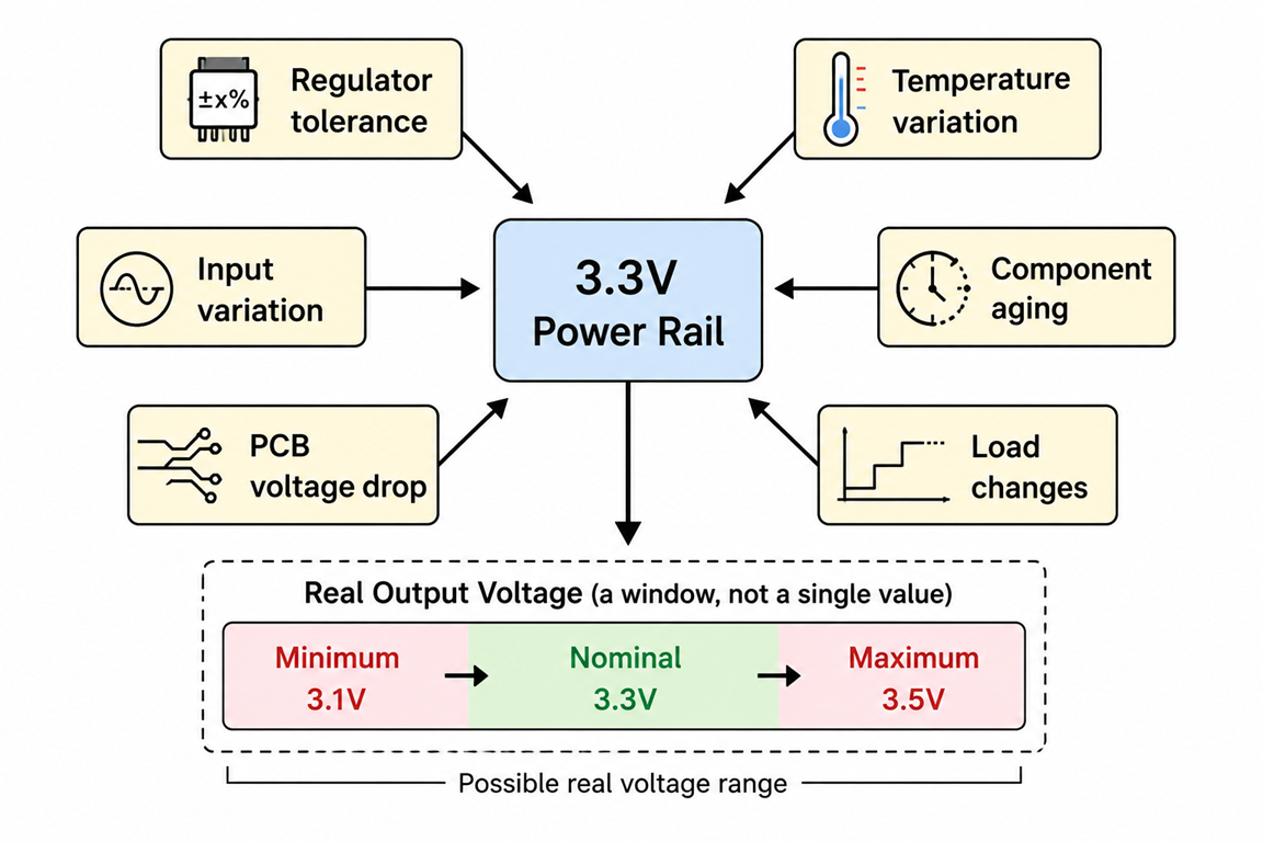
But the actual voltage experienced by components is affected by multiple variables:
- Regulator accuracy
- Reference voltage tolerance
- Feedback resistor tolerance
- Temperature drift
- Load transient response
- PCB voltage drop
- Connector resistance
- Capacitor aging
- Input voltage variation
- Component lifetime degradation
A realistic voltage model is not:
3.3VIt is:
3.3V + regulator tolerance
       + temperature variation
       + aging drift
       + system load variation
       - distribution losses
Every one of these factors consumes operating margin.
A design that only considers the nominal value is designing for the first day of life.
A robust design considers the entire lifetime.
Designing With Voltage Windows, Not Voltage Targets
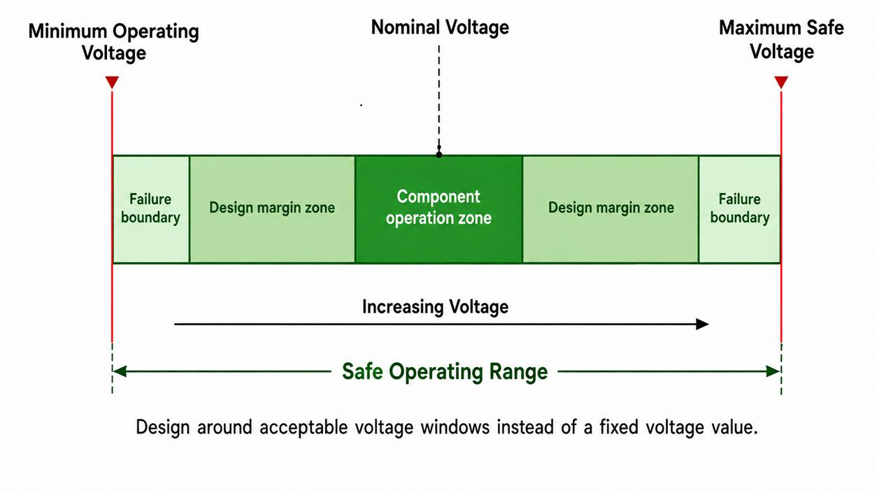
A Hoomanely hardware approach starts by defining an acceptable voltage window.
Instead of:
"Generate 3.3V"
the requirement becomes:
"The system must operate correctly between 3.15V and 3.45V throughout its lifetime."
This changes the design approach.
Every powered component needs three values:
Minimum Operating Voltage
The lowest voltage where the component remains functional.
Examples:
- MCU minimum supply voltage
- Memory retention voltage
- Sensor accuracy limit
- Communication transceiver threshold
Nominal Operating Voltage
The intended design point.
Example:
3.3V ±5%Maximum Safe Voltage
The highest voltage before reliability degradation occurs.
Examples:
- IO absolute maximum limits
- ADC reference limitations
- Sensor accuracy degradation
- Increased leakage current
The regulator is then selected and configured to keep the rail inside this window under all expected conditions.
Derating Standards: Designing Below the Datasheet Limit
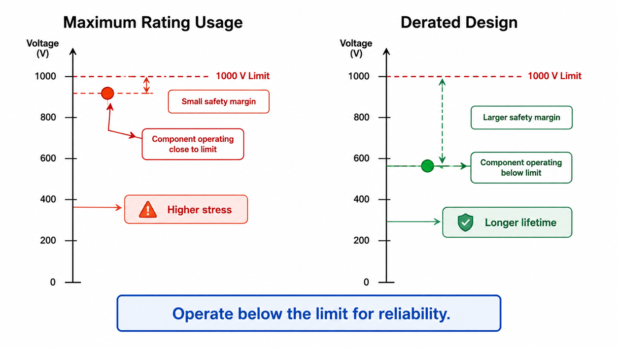
Datasheets define maximum ratings.
Reliable products are designed below them.
This difference is where derating becomes important.
A component operating continuously at its maximum specification may work during validation but may not survive long-term field conditions.
For voltage design, derating means maintaining additional electrical distance from the limits.
For example:
A memory device may support:
1.8V ±10%A short-term prototype may operate close to:
1.98VBut a production design may target:
1.80V ±5%to account for:
- regulator aging
- temperature effects
- manufacturing variation
- transient overshoot
The goal is not maximum electrical utilization.
The goal is predictable operation over product lifetime.
Understanding Regulator Aging and Drift
Regulators are often considered stable components.
They are stable, but not perfect.
Over time, several parameters change:
Reference Voltage Drift
Most regulators depend on an internal voltage reference.
This reference changes slightly with:
- temperature
- aging
- manufacturing variation
A regulator initially producing:
3.300Vmay slowly shift toward:
3.270Vor
3.340Vover years.
For digital systems, this may not matter.
For precision sensors, ADC references, communication interfaces, and analogue circuits, it can become significant.
Feedback Network Aging
The voltage setting depends on external resistors.
A typical feedback network:
VOUT
 |
 R1
 |
 FB
 |
 R2
 |
 GND
The output voltage accuracy depends on resistor tolerance and temperature coefficient.
A 1% resistor may be acceptable during initial design.
However, precision applications may require:
- lower tolerance resistors
- matched resistor networks
- temperature coefficient analysis
The regulator does not operate independently.
The complete feedback network defines long-term behaviour.
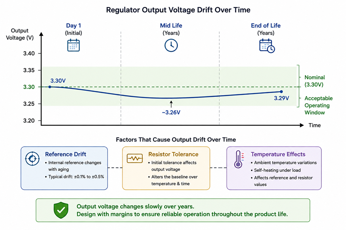
End-of-Life Voltage Drift Planning
A product specification should not only define:
"Voltage at production"
It should define:
"Voltage at end of life."
This is especially important for products expected to operate:
- 5+ years
- outdoors
- high-temperature environments
- continuous operation
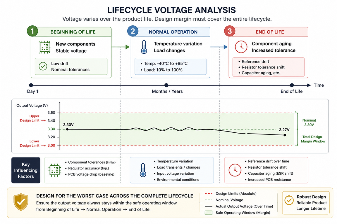
A practical lifetime analysis includes:
Beginning-of-Life Condition
Fresh components:
3.3V rail
25°C
new capacitors
new regulator
Worst-Case Operating Condition
Example:
85°C environment
maximum load
aged components
minimum input voltage
End-of-Life Condition
After years:
Regulator drift
Capacitor ESR increase
Connector resistance increase
PCB copper aging effects
The voltage margin must survive the worst combination, not just individual effects.
Capacitor Aging and Voltage Stability
Capacitors are often ignored during voltage margin calculations.
But they directly influence regulator performance.
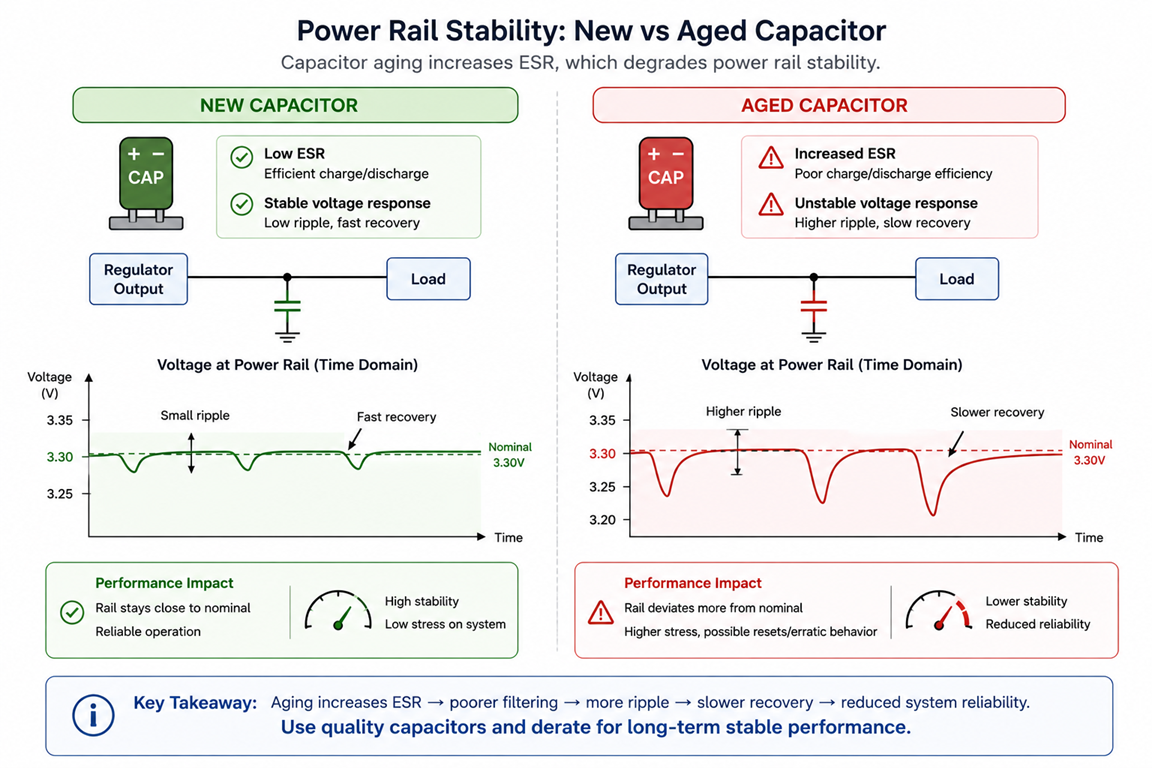
Over time:
- capacitance decreases
- ESR increases
- transient response worsens
A regulator that was stable with a new capacitor may experience:
- increased ripple
- slower recovery
- larger voltage dips
For processors, cameras, radios, and memory devices, these short voltage events can cause:
- random resets
- communication failures
- corrupted data
Aging analysis should include:
- capacitor lifetime curves
- temperature acceleration
- expected capacitance reduction
The design should still maintain acceptable voltage behavior after capacitor degradation.
Designing Voltage Margins Around Real Loads
Another common mistake is validating voltage rails using average current.
Modern products rarely operate at average load.
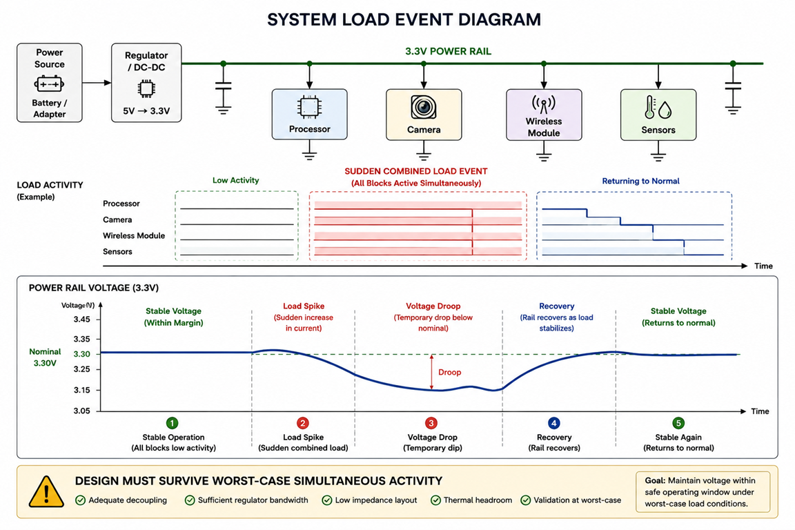
A real system may have:
- processor waking up
- camera starting
- wireless transmission beginning
- motor activating
- display turning on
all at the same time.
During these events, the voltage rail experiences:
- sudden current demand
- regulator response delay
- distribution losses
The question becomes:
"Does the rail remain inside the voltage window during maximum feature concurrency?"
not:
"Does the regulator output measure 3.3V on the bench?"
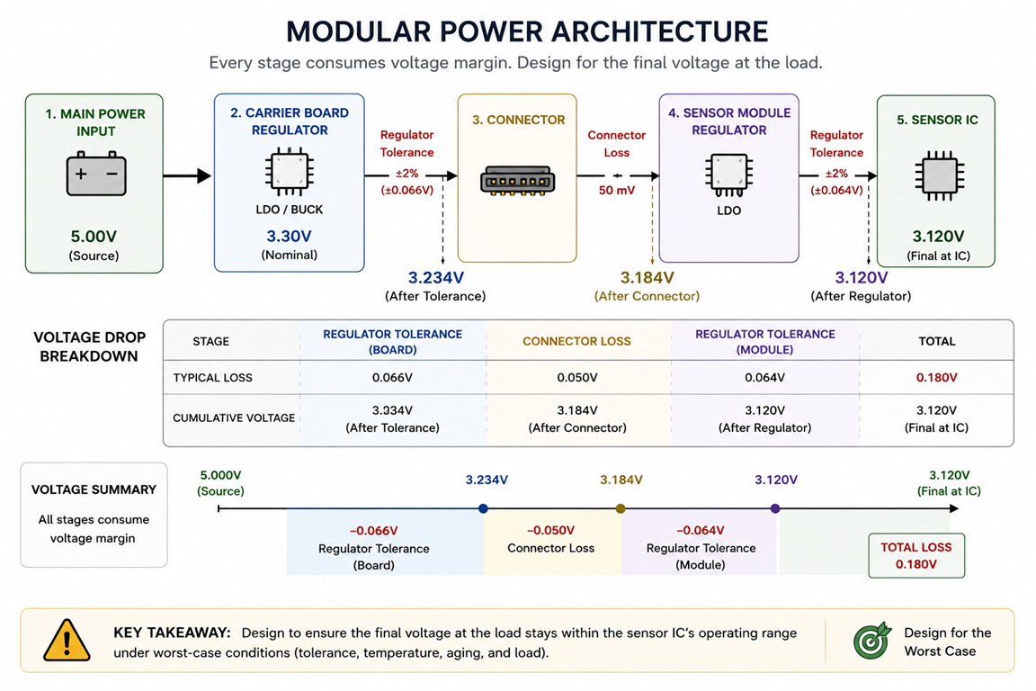
Aging-Aware Operating Margins in Modular Systems
Modern products often contain multiple boards:
- processor module
- sensor modules
- communication modules
- carrier boards
Each module introduces another voltage dependency.
For example:
Carrier board:
5V input
 |
Regulator
 |
3.3V rail
 |
Connector
 |
Sensor module regulator
 |
Sensor IC
The final sensor does not see the original 3.3V rail.
It sees:
Regulator drift
+
Connector loss
+
Trace drop
+
Module load variation
A modular architecture requires voltage margin budgeting across the entire power chain.
Hardware Features That Improve Long-Term Voltage Reliability
Good voltage margining is not only about calculations.
The architecture itself should support future reliability.
Useful hardware practices include:
Voltage Monitoring Points
Add measurement capability for:
- critical rails
- processor supply
- sensor supplies
This allows:
- production validation
- field diagnostics
- aging analysis
Programmable Regulators
Where possible:
- use adjustable regulators
- store configuration values
- allow controlled voltage tuning
This enables:
- compensation during validation
- product variant support
- future corrections
Independent Rail Control
Critical subsystems should not depend on a single uncontrolled power domain.
Separate enables allow:
- fault isolation
- controlled startup
- reduced stress during abnormal conditions

The Hoomanely Design Perspective
A voltage rail is not a number written on the schematic.
It is a living electrical system that changes with:
- time
- temperature
- usage pattern
- manufacturing variation
A product designed only around nominal voltage will usually pass initial testing.
A product designed around voltage margining survives reality.
At Hoomanely, power architecture is treated as a long-term reliability decision.
The objective is not to achieve the smallest possible voltage tolerance.
The objective is to create enough margin that the product behaves the same:
- on day one,
- after thousands of operating hours,
- after temperature cycles,
- after components have aged.
The best hardware designs are not the ones that operate closest to their limits.
They are the ones that quietly maintain stability long after the original designer has stopped looking at the board.
Design Principle:
"A reliable voltage rail is not the one that measures correctly today. It is the one that still behaves correctly when every component around it has changed."



