
Engineering Order at Scale: Device Class Governance in the vBus Ecosystem
At Hoomanely, our vBus architecture isn't just about electrical interfaces and modular hardware, it's a complete design philosophy that extends into every aspect of how we organize, manage, and deliver our products. As our ecosystem has grown to encompass dozens of SoM variants, carrier boards, and product configurations, we've discovered a fundamental truth: disciplined organization is the foundation of rapid innovation.
We call this approach Device Class Governance, a comprehensive framework for managing the entire lifecycle of hardware designs from concept through production. It rests on three pillars:
- Rigorous folder discipline
- Production file standardization
- Systematic review checklists
Folder discipline: the foundation of organized design
Every PCB design begins with a properly structured project folder, and that folder's name tells a complete story. Our naming convention encodes essential information directly into the folder name: product line, module type, variant, and version, for example "VBUS-CPU-STM32H7-V2.1" instantly identifies a vBus CPU SoM built on an STM32H7 processor at hardware revision 2.1. When an engineer sees "VBUS-PERIPH-ENV-V2.2," they instantly know it's a vBus Peripheral SoM containing environmental sensors at revision 2.2, no guessing, no cross-referencing documentation.
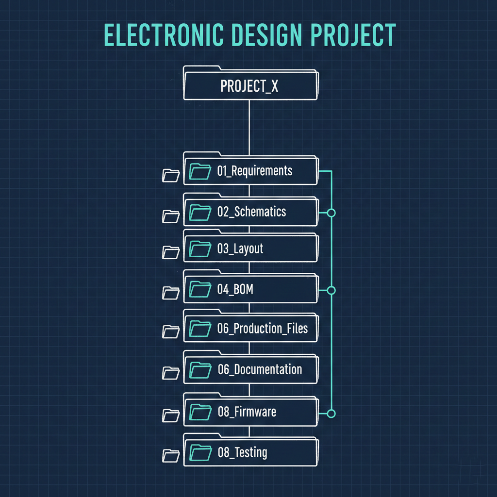
Inside each project folder we maintain a rigorous internal structure mirroring our development workflow, numbered directories for requirements, schematics, layout, BOM, production files, documentation, firmware, and testing, each with a consistent internal layout across every project.
This systematic approach delivers real advantages. Instant navigation lets any engineer locate the schematic, BOM, or production files for any design within seconds. Version control integration makes revision tracking explicit since folder names include version numbers. Cross-project consistency makes design reuse trivial, since the folder structure is identical across projects, engineers know exactly where to look for how a previous design handled a similar problem. Automated tooling can reliably operate on design files because the structure is predictable, simplifying automated BOM extraction, gerber validation, and documentation generation. Manufacturing handoff has zero ambiguity, since everything manufacturing needs lives in the same numbered production files directory across every project. And knowledge preservation means engineers supporting legacy products years later can quickly understand the complete design history because documentation lives in predictable locations.
Production file expectations: manufacturing-ready from day one
Production files inherit the same naming convention as their parent folder, creating an unbreakable link between design and manufacturing artifacts. Gerber files, assembly drawings, pick-and-place data, and BOMs all share the same base identifier, eliminating one of manufacturing's most common sources of confusion: which files belong together. When every file shares the same base identifier, assembling the correct documentation package becomes foolproof.
We've defined exactly what constitutes a complete production package. Fabrication files include the complete gerber set, NC drill files with tool definitions, board outline and dimensional drawing, stackup specification with impedance requirements, and material and finish requirements. Assembly files include top and bottom assembly drawings with reference designators, a pick-and-place CSV with coordinates and rotation, a manufacturing BOM with exact part numbers, component placement notes for special-handling parts, and paste stencil specifications where non-standard. Quality control files include a test point location map, electrical test specifications, visual inspection criteria, first-article inspection requirements, and acceptance criteria. Documentation includes design intent notes on critical traces and thermal considerations, known issues or errata, rework procedures, revision history, and engineering contact information.
Before any design is released to manufacturing, it passes through a standardized handoff checklist confirming the folder name matches version and variant, all production files use consistent naming, gerbers are validated with a third-party viewer, pick-and-place coordinates are verified against the assembly drawing, the BOM matches the schematic component count, all components have valid manufacturer part numbers, second-source options are documented for critical components, test specifications reference the correct test points, programming instructions are validated on prototype hardware, and design review sign-off documentation is included. This checklist ensures manufacturing receives complete, accurate, production-ready files on the first submission, no back-and-forth, no missing documents, no ambiguity.
Review checklists: engineering excellence through systematic validation
We've developed comprehensive design review checklists that systematically validate every aspect of a design before it progresses to the next stage. These aren't bureaucratic hurdles, they're structured frameworks that help engineers deliver their best work.
The schematic review checklist covers electrical integrity (power nets annotated with voltage and current budget, signal nets following vBus naming conventions, decoupling capacitors at every power pin, pull-up and pull-down resistors on critical signals, ESD protection on external interfaces, no unconnected pins on active components), interface compliance (vBus connector pinout matching standard, communication interfaces properly terminated, differential pairs impedance-matched, clock signals with series termination, debug interfaces accessible and properly configured), power distribution (sequencing requirements documented, current budget analysis completed, voltage regulation margins verified, thermal dissipation calculated, ground domains properly isolated), and component selection (second-source alternatives documented, lifecycle status verified as not end-of-life, operating temperature ranges meeting requirements, package availability confirmed for volume production).
The PCB layout review checklist covers mechanical compliance (board dimensions matching the mechanical drawing, mounting holes positioned correctly, connector placement matching vBus standard locations, component height restrictions observed, keep-out zones respected), signal integrity (high-speed traces impedance-controlled, differential pairs length-matched, critical signals avoiding split planes, clock traces following best practices, return paths verified), power integrity (power plane copper area adequate, via stitching at plane boundaries, decoupling capacitors close to power pins, thermal vias under power components, current density verified), and manufacturing considerations (trace widths meeting minimums, clearances satisfying fabrication rules, via sizes within capabilities, component footprints matching manufacturer drawings, legible silkscreen, fiducials placed for automated assembly).
The BOM and documentation review confirms component count matches the schematic, all components have manufacturer part numbers, second-source alternatives are documented, lifecycle tracking data is current, cost analysis is completed, lead time is assessed, assembly notes are complete, and test procedures reference the correct revision.
The review culture
Our checklists aren't just documents, they're living tools engineers actively use and continuously refine. No design progresses without at least two reviewers beyond the original designer, fresh eyes catch what familiarity misses. Rather than constraining creativity, checklists free engineers to focus on innovation by handling routine verification systematically. When a checklist item repeatedly catches issues, we enhance our templates and training, and when checklists miss something, we add the new check immediately. Cross-functional participation matters too, firmware engineers review schematics for firmware compatibility, manufacturing engineers review layouts for assembly considerations, quality engineers validate test specifications. Every reviewer signs off digitally with timestamp and comments, creating accountability and a clear audit trail.
The efficiency multiplier
Our systematic review process delivers measurable results:
- Above-95% first-pass PCB success
- Manufacturing queries reduced by 80% thanks to complete
- Clear documentation
- Time to production roughly 30% faster from design freeze to manufacturing release
- Fewer engineering change orders during development
- Field failure rates significantly below industry averages
These improvements aren't accidental, they're the direct result of rigorous, systematic validation at every stage.
Integration: how governance enables vBus excellence
Device Class Governance isn't separate from vBus architecture, it's the organizational framework that makes vBus scalable and sustainable. Folder discipline plus modularity means each SoM type has its own design folder, but all follow an identical internal structure, making SoM-to-SoM comparison trivial and design reuse effortless. Production files plus standardization means every SoM uses standard vBus connectors, so production files share common elements and manufacturing learns the pattern once and applies it everywhere. Review checklists plus quality means vBus-specific validation items, like connector pinout verification and interface compliance, are built into checklists, ensuring every design maintains ecosystem compatibility. And naming convention plus traceability means when a field issue arises, the folder name, production file names, and version control history create an unbroken chain from symptom back to exact design revision and BOM configuration.
Conclusion: structure as a competitive advantage
Device Class Governance might seem like administrative overhead, but it's actually a force multiplier that accelerates everything we do. When folders follow predictable structure, when production files carry complete information, when reviews systematically validate every detail, engineering teams can move fast with confidence.
At Hoomanely, we've learned that discipline and velocity aren't opposites, they're complements. The same governance framework that ensures quality also enables speed. The same review checklists that catch errors also preserve institutional knowledge. The same folder structure that organizes current designs also makes legacy products maintainable. As our vBus ecosystem continues to grow, Device Class Governance scales effortlessly with it, new SoM types fit naturally into existing structures, new engineers adopt proven patterns immediately, and new manufacturing partners receive clear, complete information from day one.



