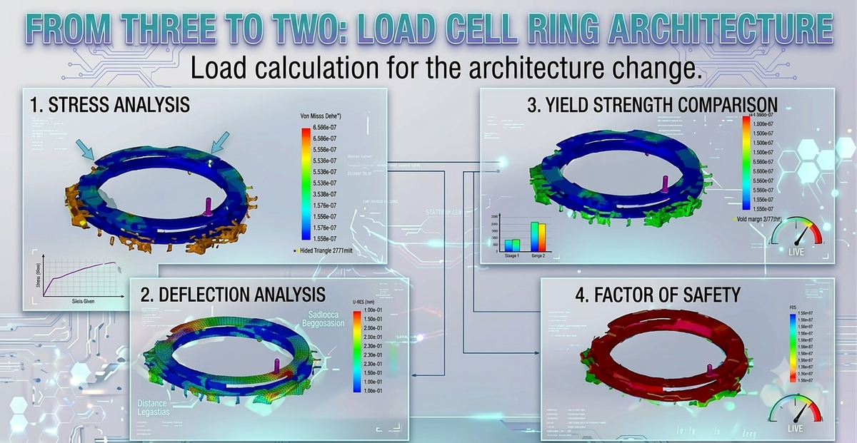
From Three to Two: Load calculation for the Load Cell Ring Architecture
Hardware redesigns rarely happen in isolation. A change to one subsystem ripples outward — and what looks like a simple reduction in sensor count can cascade into new structural constraints, new joining challenges, and a fresh round of stress calculations. This is the story of moving our ring scale from three load cells to two: what drove the decision, what broke along the way, and what the engineering analysis revealed.
The original setup: three cells at 120°
The first version of the scale used two concentric aluminium rings — a top ring where the bowl sits (OD 245.5 mm, 2.5 mm thick) and a bottom ring (OD 256 mm, 2.0 mm thick), both 6061-T6 aluminium with a 198 mm central cutout. Three bar-type aluminium load cells sat between the rings at 120° spacing, each fixed with screws through a 3 mm bean-shaped spacer. The spacer created a deliberate cantilever effect: one end of the load cell was the fixed point, the other the load point, with a hole-to-hole moment arm of 64.45 mm.
The electronics followed a two-board architecture: a load cell PCB that carried the sensors connected to a separate carrier board housing the ADC. Each load cell signal ran back to a centralised ADC over a cable harness.
It worked. But the architecture carried complexity that didn't need to be there.
Why we moved to two load cells
The driving reason was electronics consolidation, not mechanical preference. The goal was to move the ADC onto the load cell PCB itself — making each sensor a self-contained digital unit that speaks directly to the carrier board over a digital bus. This change eliminates the analogue cable runs, reduces noise susceptibility, and simplifies the carrier board significantly.
The move to two load cells at 180° followed directly from this: two PCBs, two digital outputs, one carrier board reading both. A three-cell layout with on-board ADCs would have required managing three independent digital channels and added a third PCB to an already compact assembly. Two cells at 180° is the simpler, cleaner architecture.
There was also a secondary benefit: symmetric 180° placement simplifies the weight calculation to a direct sum — R₁ + R₂ = W — with no angular correction factors needed.
The joining problem: why screws were out
Screws were the original fastening method and they worked well for three cells. Moving to two cells changed the load geometry enough that the screw approach became problematic — the reduced cell count concentrates more load per joint, and the 180° layout creates a stronger moment arm effect under off-axis loading than the 120° layout.
The first replacement approach was direct welding. It failed immediately. The gap between the load cell bar and the ring is tight by design — the 3 mm spacer is there precisely to create the cantilever gap — and this geometry makes clean weld access impossible. The welds that did form cracked at the heat-affected zone due to the dissimilar stiffness between the thin spacer and the ring body.
The second attempt was weld paste (JB Weld cold weld epoxy). It bonded, and it held — up to a point. Under heavier loads, it failed suddenly. Understanding why it failed drove the rest of the engineering analysis.
Why JB Weld fails under load: the peel problem
JB Weld is a cold weld epoxy — it forms a dense, cross-linked polymer network that is effectively metal-hard with zero flexibility. Under pure shear loading, where the force is distributed across the full bond area, it performs well. The problem is the cantilever geometry.
With the load cell acting as a cantilever, the fixed-end spacer joint sees not just shear but a bending moment. This generates peel stress — a force that tries to lift one edge of the bond while compressing the opposite edge. Because JB Weld cannot deform, all of that peel force concentrates at a single edge. Once the stress at that edge reaches the adhesive's lap shear limit, the crack propagates instantly across the full bond. The result is sudden, total joint failure — exactly what was observed.
The replacement: Loctite EA 9466, a two-part flexible epoxy. Its lap shear strength is comparable to JB Weld (7.2 MPa), but it retains enough elongation to redistribute peel stress across the bond rather than concentrating it at one edge. At the load cell interface specifically — where the contact area is small and peel risk is highest — this material difference raises the FOS from 2.49 to 8.3 with no geometry change.
The calculations: what the transition demanded
With the joining method settled, the structural analysis quantified exactly what the two-cell layout requires at each load case.
Force distribution. At 5 kg total load, each cell carries 24.53 N and generates a bending moment of 1.581 Nm at the fixed-end spacer.
Spacer stress at 5 kg. With the original bean-shaped spacer (52.63 mm × 5 mm), the combined shear and bending stress at 5 kg is 0.863 MPa — well within JB Weld's limit. FOS = 9.3. The original spacer geometry was adequate for the original load range.
The key insight from the calculation: bending stress is governed by the spacer's moment of inertia I = w × L³ / 12. Length is cubed in this term — doubling the spacer length reduces bending stress by 8×. This makes length the single most powerful design variable. The required spacer for 50 kg at FOS ≥ 3 is 120 mm × 8 mm, along with a 4 mm concave fillet bead at all edges.
The two bond interfaces. The spacer has two bond faces: one to the ring (Interface 1, 960 mm² contact area) and one to the load cell body (Interface 2, 240 mm² contact area). Interface 1 achieves FOS 6.68 with JB Weld at 50 kg — safe. Interface 2, with its shorter contact length and much lower moment of inertia (8,433 mm⁴ vs 1,152,000 mm⁴), achieves only FOS 2.49 — marginal. The fix for Interface 2 is the adhesive upgrade to EA 9466 plus extending contact length to 28 mm where geometry permits.
What the analysis exposed that the three-cell setup hid
Three cells at 120° distribute load more evenly and create shorter individual moment arms under off-axis loading. The 180° two-cell layout is mechanically simpler to analyse but more sensitive to moment concentration — both cells carry higher individual loads and the fixed-end joint sees the full bending moment without the triangulated support that three points provide.
This doesn't make two cells the wrong choice — the electronics simplification is real and significant. But it means the joint engineering has to be done properly. The three-cell version with screws could tolerate more geometric imprecision because mechanical fasteners distribute load across thread engagement length. Adhesive joints are unforgiving of peel stress in a way that screws are not.
Final design state
| Parameter | Three-cell original | Two-cell revised |
|---|---|---|
| Cell count | 3 | 2 |
| Angular spacing | 120° | 180° |
| Fastening | Screws | EA 9466 (LC interface) + JB Weld (ring interface) |
| Spacer geometry | 52.63 × 5 mm | 120 × 8 mm with 4 mm fillet |
| ADC location | Carrier board | On each load cell PCB |
| Target load range | 3–5 kg | 3–5 kg (50 kg with cell upgrade) |
| Interface 2 FOS | Not calculated | 8.3 (EA 9466) |
| Ring thickness needed | 2.5 / 2.0 mm | 8 mm min for 50 kg; 2.5 mm sufficient at 5 kg |
About Hoomanely
This load cell redesign reflects the kind of first-principles hardware work that underpins Hoomanely's sensing technology. Moving from three cells to two wasn't just a parts reduction — it was a deliberate architecture decision that touched electronics integration, structural mechanics, and materials selection simultaneously. Hoomanely's approach to sensing hardware is to understand every failure mode analytically before it appears in the field, and to make design changes that are justified by calculation, not just intuition.
Key takeaways:
- The move from 3 to 2 load cells was driven by electronics consolidation — placing the ADC on each load cell PCB eliminates analogue cable runs and simplifies the carrier board
- Direct welding failed due to geometric constraints; JB Weld failed under the cantilever's peel stress — both failure modes have structural, not process, root causes
- Bending stress at the spacer joint is controlled by spacer length cubed; doubling length reduces bending stress by 8×
- Interface 2 (spacer to load cell) is the governing joint — EA 9466 raises its FOS from 2.49 to 8.3 with no geometry change
- The 180° two-cell layout is more moment-sensitive than the 120° three-cell layout; proper joint engineering is non-negotiable