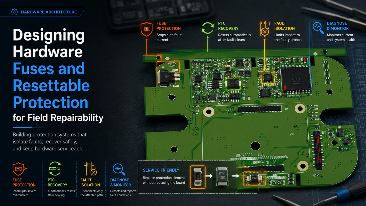
Designing Hardware Fuses and Resettable Protection for Field Repairability
Building products that protect themselves without turning every fault into a service nightmare
A hardware protection circuit is usually designed with one question in mind:
"How do we prevent this fault from damaging the board?"
That question is important, but in real products it is incomplete.
A product does not only need to survive faults. It needs to recover from them.
When a device is deployed in the field, failures do not happen inside a controlled laboratory environment. A user may connect the wrong accessory, a cable may short temporarily, a connector may be damaged, or a subsystem may fail internally. The difference between a repairable product and an expensive return often comes down to what happens after the protection circuit reacts.
A fuse that protects the board but permanently disables a product may avoid hardware damage but create a service problem.
A resettable protection device that recovers automatically may keep the product alive but could hide a repeated fault.
The goal is not simply adding protection.
The goal is designing protection behaviour.
In Hoomanely hardware architecture, protection is considered part of the user experience. A device should fail in a controlled way, communicate what happened, and provide a practical recovery path.
Protection Components Are Not Just Safety Devices
A common approach in hardware design is selecting a fuse based only on current rating.
For example:
"The rail consumes 2A, so we select a 3A fuse."
This works electrically, but it ignores the system behaviour.
A protection component sits between normal operation and abnormal conditions.
That means its characteristics affect:
- Startup behaviour
- Peak current handling
- User recovery
- Manufacturing testing
- Service replacement
- Long-term reliability
A good protection design answers questions like:
- What faults should disconnect immediately?
- What faults should recover automatically?
- What faults require user intervention?
- What faults should be visible during debugging?
- What components should be replaceable?
The protection strategy becomes a part of the product architecture.
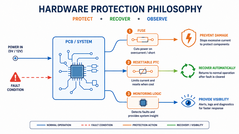
Choosing Between Permanent Fuse and Resettable Protection
The first design decision is understanding where permanent isolation is valuable and where automatic recovery is better.
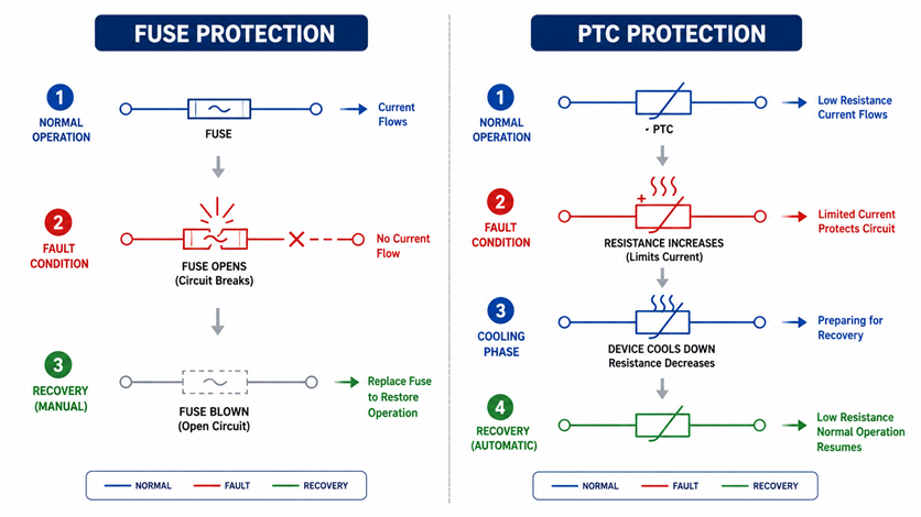
Permanent Fuse Protection
Traditional fuses are useful when the priority is preventing catastrophic damage.
Examples:
- Battery input protection
- High-energy external power input
- Dangerous short-circuit paths
- Protection against wiring mistakes
Once triggered, the fuse opens permanently.
The advantage is clear:
The fault cannot repeatedly stress the system.
But the limitation is equally clear:
The user cannot recover without replacement.
For sealed products, this can mean:
- Device shipment back to service centre
- Additional labour cost
- Longer downtime
Resettable PTC Protection
Polymeric Positive Temperature Coefficient devices (PTCs) provide a different behaviour.
During a fault:
- Current increases
- PTC heats up
- Resistance rises significantly
- Current reduces
- After cooling, normal operation returns
This behaviour is useful for faults that are temporary.
Examples:
- External accessory ports
- USB power outputs
- Sensor supply branches
- User-accessible connectors
The device protects itself without requiring replacement.
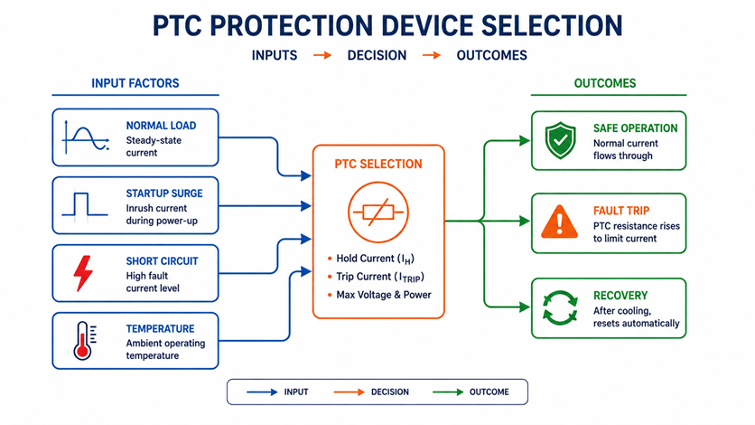
However, PTC selection requires more than looking at the hold current.
Important parameters include:
- Hold current
- Trip current
- Maximum voltage
- Resistance during normal operation
- Resistance after trip
- Recovery time
A poorly selected PTC can create new problems:
- Voltage drop during normal operation
- Slow startup
- Unpredictable recovery
- Excessive heating
Selecting PTC Protection Based on Real Operating Conditions
One mistake in embedded products is selecting PTC values based only on nominal current.
Real devices have dynamic behaviour.
Consider an accessory port.
Normal condition:
- Sensor connected
- 200mA operating current
Temporary event:
- Startup surge
- 600mA for 100ms
Fault condition:
- Cable short
- Several amps continuously
The PTC must distinguish between these three states.
If the trip threshold is too low:
The product may fail during normal operation.
If the threshold is too high:
The board may experience unnecessary stress before protection activates.
The correct selection process considers:
- Maximum normal load
- Startup current
- Environmental temperature
- Fault duration
- Recovery expectation
Temperature is especially important.
A PTC operating near a hot regulator or processor will behave differently compared to one placed in a cooler region.
Protection components are part of thermal architecture.
Fuse Coordination: Preventing the Wrong Component From Failing
In complex products, there are often multiple protection layers.
For example:
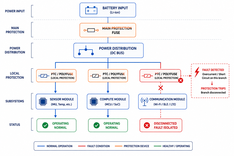
Battery input → Main fuse → Power distribution → Subsystem protection → Individual loads
The question becomes:
Which protection device should react first?
Without coordination, a small subsystem fault can trigger a larger protection element.
Example:
A camera module develops a short.
Poor architecture:
Battery fuse opens.
Result:
The entire product shuts down.
Better architecture:
Camera branch protection reacts first.
Result:
Only the camera subsystem disconnects.
The rest of the product continues operating.
This is fault containment applied through protection design.
Good fuse coordination considers:
- Fault location
- Current path
- Energy available
- Protection response time
The protection nearest to the fault should ideally handle the fault before upstream protection activates.
Designing Replaceable Protection Instead of Replaceable Boards
A field failure should not automatically become a PCB replacement.
This sounds obvious, but many products make servicing unnecessarily difficult.
Examples:
A power input fuse placed underneath a shield.
A resettable protection device selected incorrectly.
A protection component integrated into a non-replaceable module.
The result:
A simple overcurrent event becomes a complete board replacement.
A service-friendly design asks:
"What is the smallest replaceable element after a failure?"
Possible strategies:
External replaceable fuse
Useful for:
- High-power systems
- Industrial products
- Battery systems
Accessible protection module
Useful when:
- Field replacement is expected
- Multiple configurations exist
Resettable protection
Useful when:
- User access is limited
- Faults are usually temporary
The protection strategy should match the expected service model.
Fault Isolation: Protecting the Rest of the Product
Modern devices are no longer single-board systems.
They contain:
- Compute modules
- Sensor boards
- Audio boards
- Communication modules
- Expansion boards
Shared power creates shared risk.
A failure on one module should not bring down everything else.
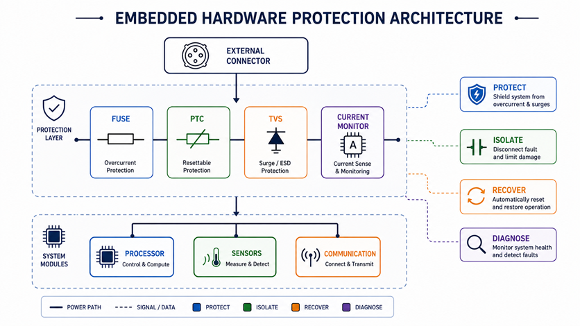
A better architecture creates protection boundaries.
For example:
Main Power Rail
↓
Protected Distribution
↓
Individual Subsystem Rails
↓
Local Protection
Each subsystem receives controlled power.
If one module fails:
- Its power can disconnect
- Fault current stays local
- Main system remains available
This approach improves:
- Reliability
- Debugging
- Field replacement
- Manufacturing yield
A product that fails locally is easier to repair than one that fails globally.
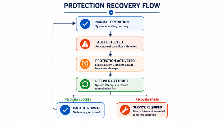
Designing Recovery Behaviour After Protection Triggers
Protection activation is not the end of the event.
The recovery behaviour matters.
A good system defines:
What happens immediately?
Example:
A short occurs on an external sensor port.
Expected:
- Sensor power removed
- Main processor continues running
- Fault logged
How does recovery happen?
Possible methods:
- Automatic retry after delay
- User power cycle
- Service reset
- Physical replacement
How does the system communicate the problem?
Useful indicators:
- Status LED pattern
- Diagnostic logs
- Service interface message
A protection event without visibility creates unnecessary debugging effort.
Avoiding Silent Protection Failures
One of the biggest field problems is protection that works but provides no information.
Example:
A PTC repeatedly trips.
The device appears randomly disconnected.
A service engineer sees no permanent damage.
Without fault history, the root cause becomes difficult.
A better architecture records protection events:
- Overcurrent detected
- Subsystem disabled
- Recovery attempted
- Recovery successful/failed
This transforms protection from a passive component into an observable system behaviour.
Practical Design Approach for Hoomanely Hardware Architecture
When designing protection circuits, the questions should be:
- Can this fault damage another subsystem?
- Should this fault recover automatically?
- Can a technician identify what happened?
- Can the smallest possible part be replaced?
- Will protection behave consistently across temperature?
- Will manufacturing teams understand the fault state?
Protection is not only about surviving failure.
It is about reducing the impact of failure.
Final Thoughts
A reliable product is not one that never experiences faults.
Every real product eventually encounters:
- Misuse
- Cable failures
- Environmental stress
- Component ageing
- Unexpected user behaviour
The difference is how gracefully it handles them.
A well-designed fuse or resettable protection circuit does more than protect silicon. It protects the user's experience, the service team's time, and the product's reputation.
The best hardware protection does not announce failure by making the entire product disappear.
It isolates the problem, preserves what still works, and creates a clear path back to operation.
That is the difference between a protected device and a service-friendly product.