
Keeping High-Speed Signals Clean Across Board-to-Board Links
High-speed signals do not fail loudly. They fail quietly. A system boots, data starts flowing, and everything appears normal, until you begin seeing intermittent frame drops, occasional communication retries, unexplained latency, or sensors behaving inconsistently under load.
The root cause is often not firmware. It's the path those signals take between boards. In modern embedded systems, especially modular architectures, high-speed interfaces rarely stay confined to a single PCB. They travel across connectors, flex cables, mezzanine links, or board-to-board stacking interfaces. And that transition, from one board to another, is where signal integrity is most vulnerable.
At Hoomanely, we treat board-to-board signal transfer not as an extension of routing, but as a critical interface boundary. Because the moment a signal leaves a board, it stops being just a trace. It becomes a system-level behavior.
The hidden problem: "it works on the PCB"
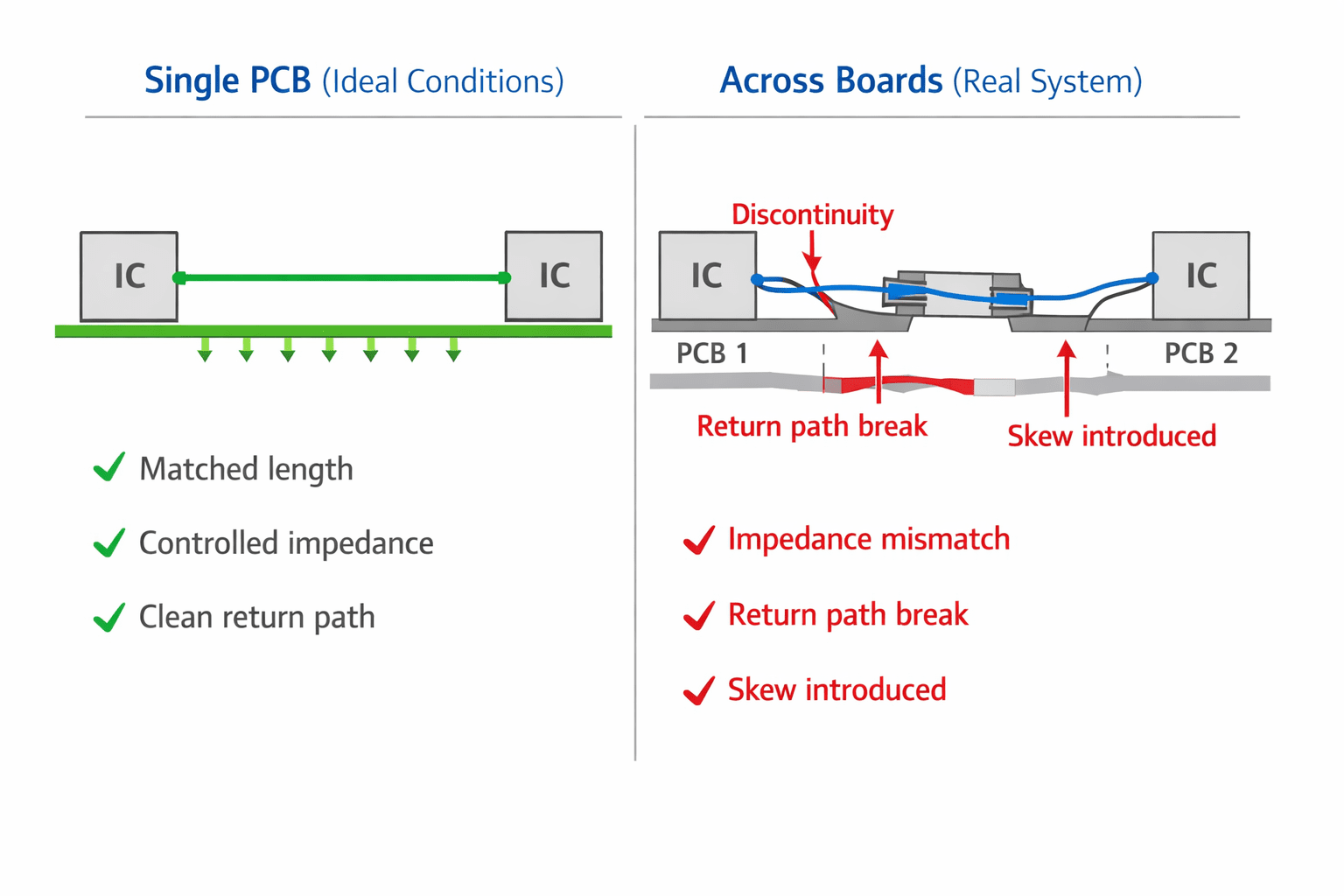
A high-speed interface may look perfect within a single board, trace lengths are matched, impedance is controlled, return paths are continuous, routing is clean. But when that same signal crosses into another board, impedance changes at the connector, return path discontinuities appear, pin mapping introduces asymmetry, stubs form unintentionally, and reference planes shift.
The result is subtle. The system still works, but not reliably under all conditions. This is why high-speed issues often appear late in development or only under stress conditions. Because they're not obvious layout mistakes. They're interface boundary problems.
A connector is not a transparent medium
One of the biggest misconceptions in multi-board design is treating connectors as neutral. They are not. A connector introduces impedance discontinuities, additional parasitic capacitance and inductance, unequal pin coupling, skew between differential pairs, and return path fragmentation. Even a well-designed connector can degrade signal quality if pin assignments aren't planned, ground reference isn't continuous, signal pairs are split across regions, or routing into and out of the connector is inconsistent.
At Hoomanely, we treat connectors as part of the signal path, not just mechanical links, so connector selection, pin mapping, and surrounding layout are all considered together.
Differential pairs must stay pairs across boards
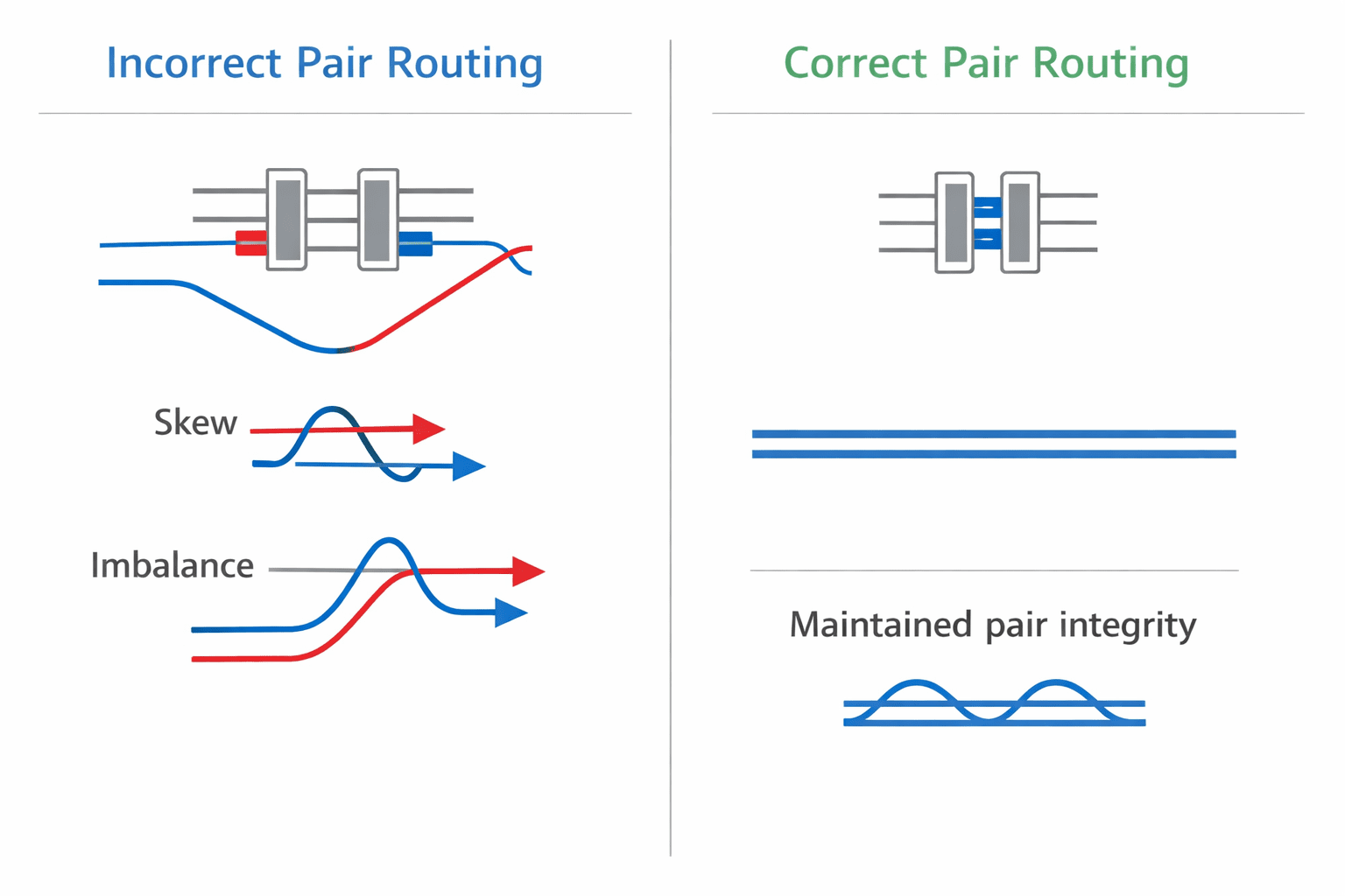
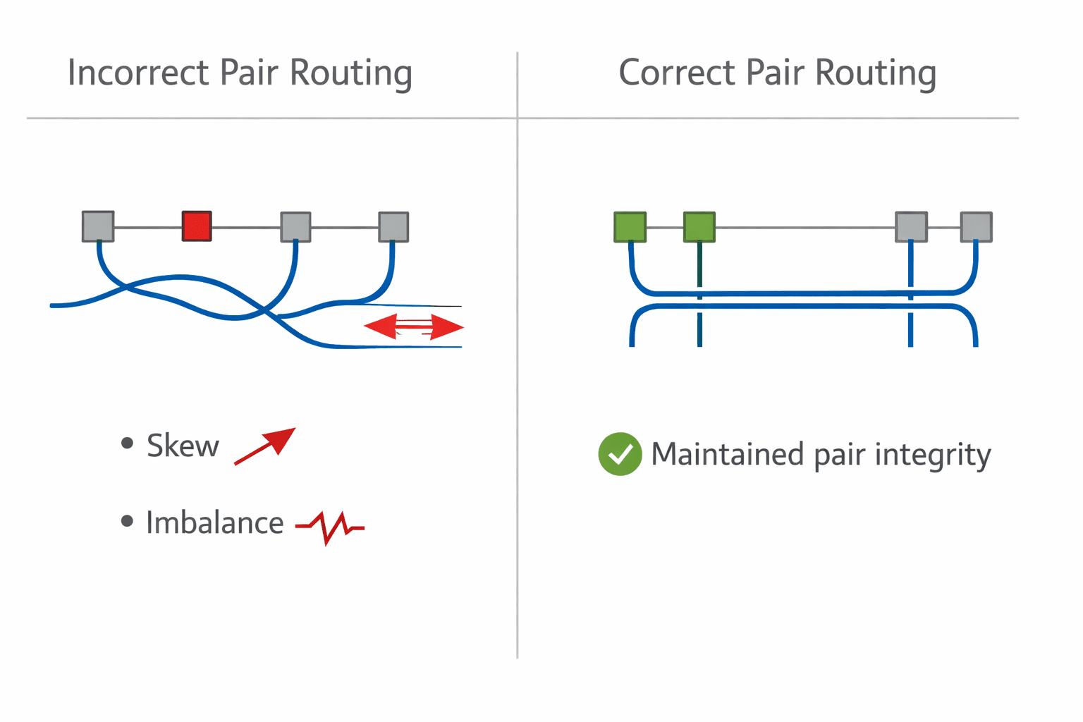
Inside a PCB, maintaining differential pair integrity is straightforward. Across boards, it becomes harder. Common mistakes include splitting differential pairs across connector rows, routing each line through different reference conditions, introducing unequal via transitions, and allowing asymmetry in entry and exit routing. This creates skew between signals, imbalance in impedance, increased common-mode noise, and a degraded signal eye.
To prevent this, we enforce paired pins in connectors, symmetrical routing on both boards, consistent reference plane transitions, and minimal skew across the entire path. A differential pair is not two signals. It's one system. That system must remain intact across the entire path.
Return paths are often the first casualty
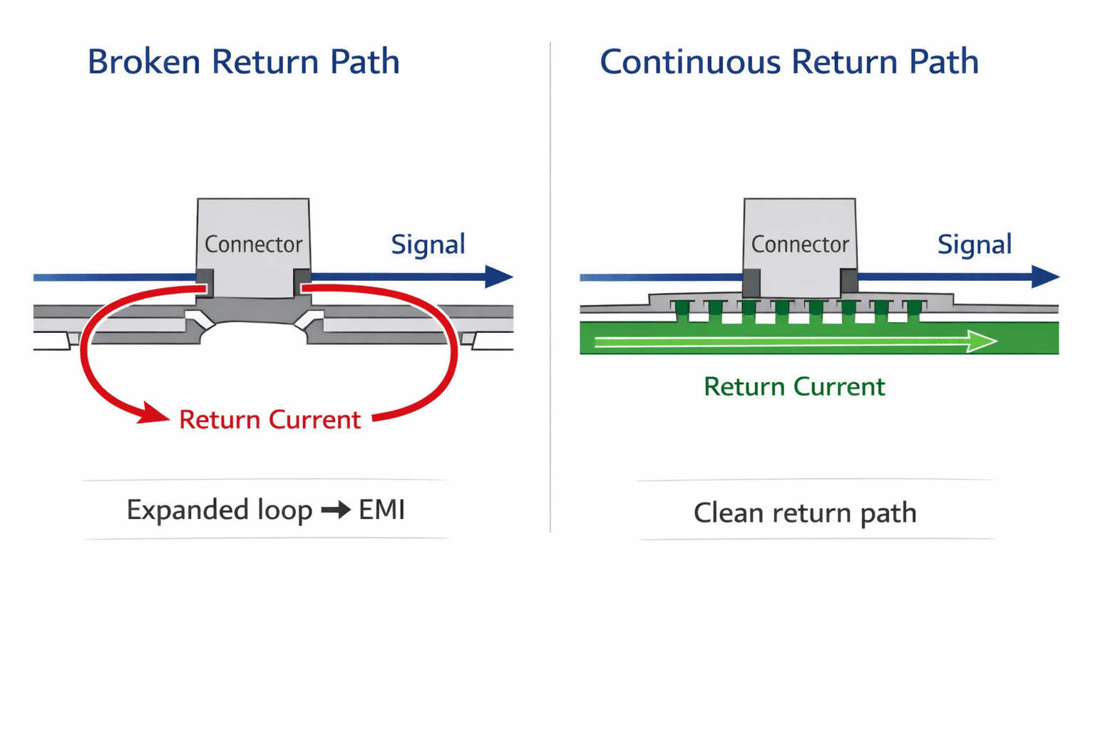
High-speed signals don't travel alone, they depend on return paths. Inside a PCB, return current flows cleanly under the trace through a reference plane. But at a board-to-board boundary, reference planes may not align, ground continuity may be broken, return current may be forced to detour, and current loops may expand, increasing EMI, signal distortion, jitter, and susceptibility to noise.
So we design connectors with ground strategy in mind, not just signal count:
- Ground pins adjacent to high-speed signals
- Continuous ground stitching across connectors
- Maintaining reference continuity across boards
- Avoiding floating or fragmented ground regions
A signal path is only as good as its return path.
Stubs are silent signal killers
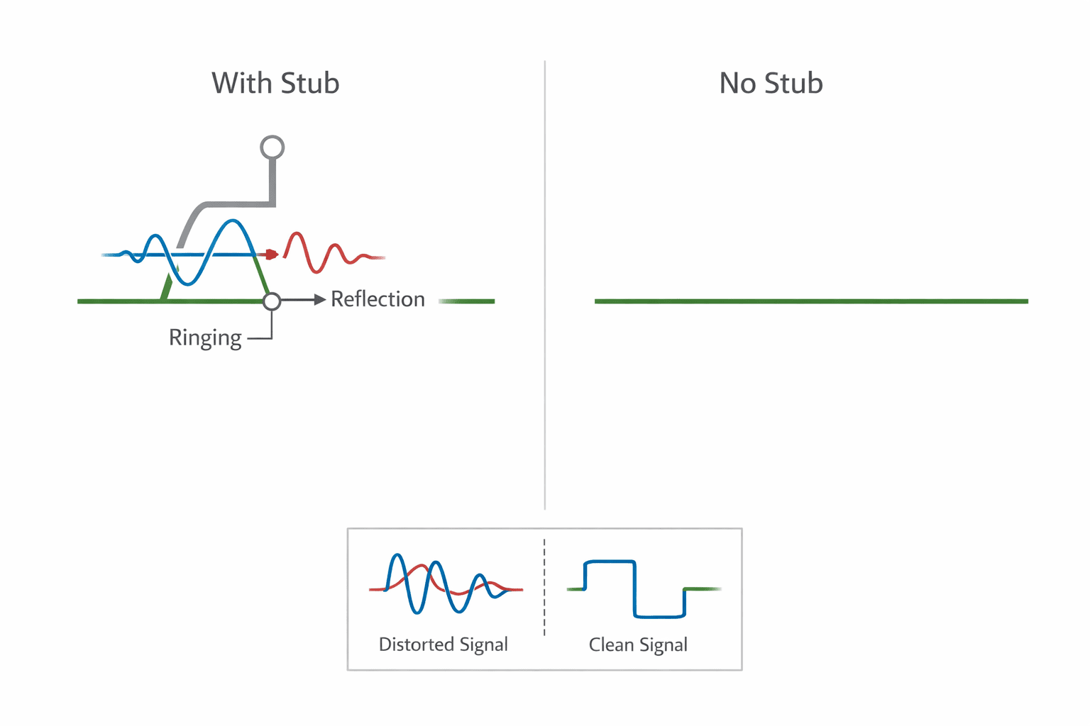
Stubs are one of the most common hidden issues in board-to-board design, appearing when unused connector pins branch off the signal path, test points get added incorrectly, routing splits unnecessarily, or debug hooks remain attached. Even small stubs can reflect energy back into the signal, causing ringing, reduced signal integrity, timing uncertainty, and degraded eye diagrams. At high speeds, even a few millimeters matter.
So we enforce no unnecessary branches on high-speed lines, minimal stub length, careful placement of test access points, and clean point-to-point routing across boards. If a signal branches, it must be intentional, not incidental.
Routing into the connector matters as much as the connector itself
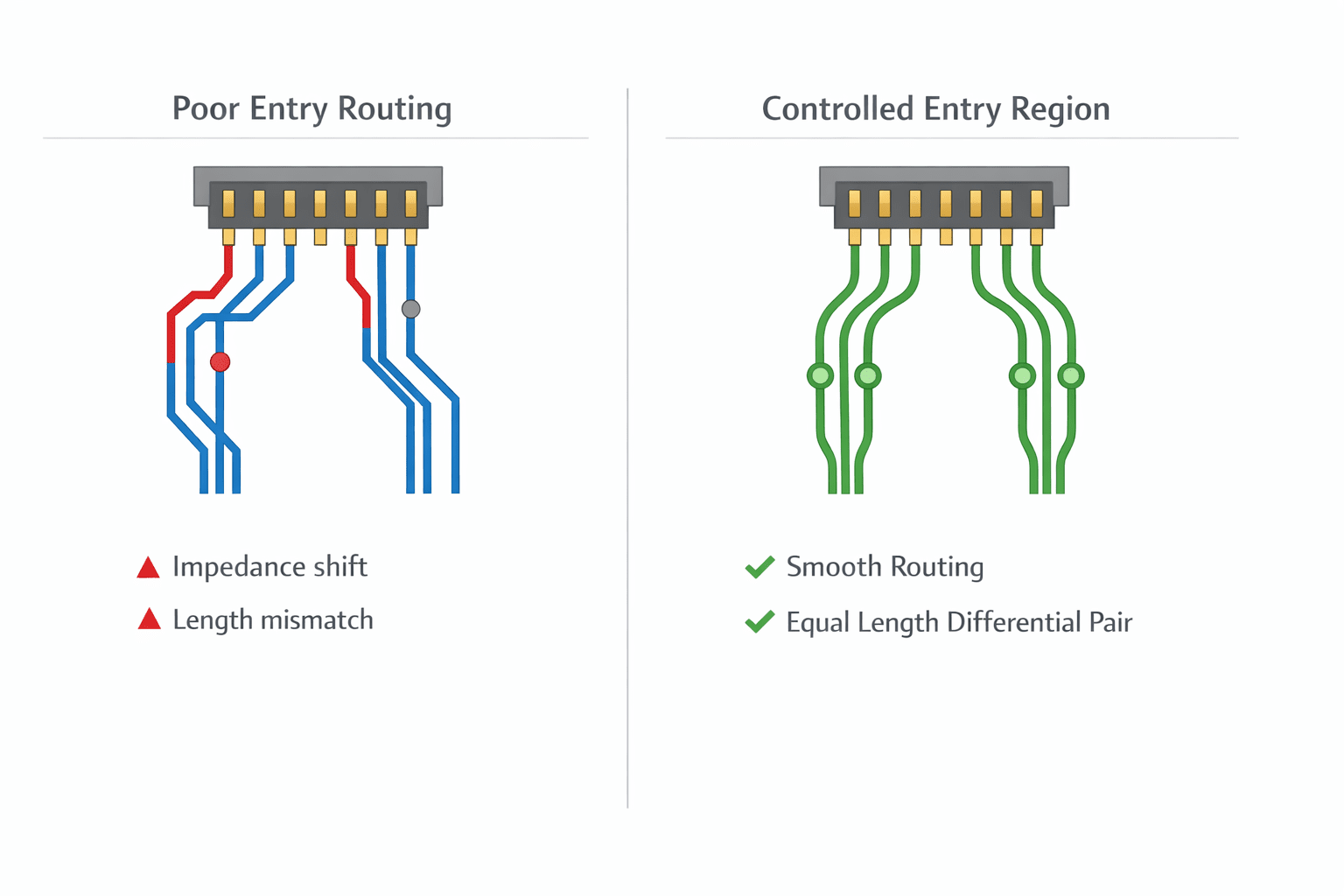
Even if the connector is well chosen, poor routing into it can degrade performance. Common issues include abrupt impedance changes near connector entry, uneven trace lengths before entering pins, different layer transitions for paired signals, and inconsistent via usage, all introducing discontinuities before the signal even reaches the connector.
At Hoomanely, we treat the connector entry region as a controlled transition zone, maintaining impedance up to the pin, avoiding sharp geometry changes, keeping differential pair spacing consistent, using symmetric via transitions, and preserving reference planes near entry. The connector doesn't fix poor routing. It amplifies it.
Cable and flex interfaces add another layer of complexity
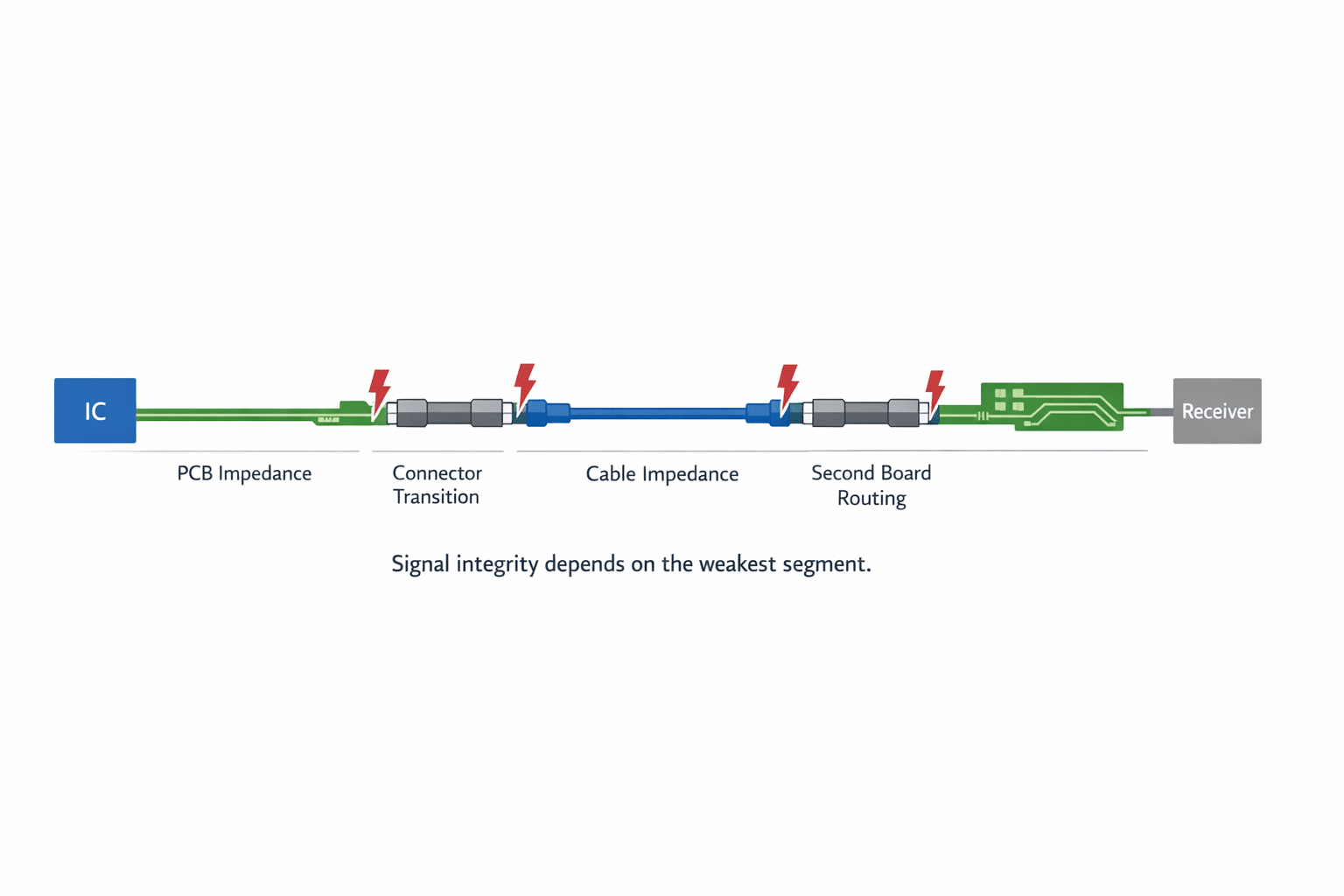
When signals leave rigid boards through flex or cables, the challenge increases, adding PCB-to-connector-to-cable-to-connector-to-PCB transitions, each introducing impedance mismatch, additional capacitance, mechanical variability, and coupling effects. To manage this, we choose cable impedance carefully, match PCB routing to cable characteristics, maintain signal pairing across the entire path, avoid unnecessary transitions, and validate the full path, not just segments. A high-speed link is only as strong as its weakest segment, and in multi-board systems, that segment is often outside the PCB.
Practical improvements we observed
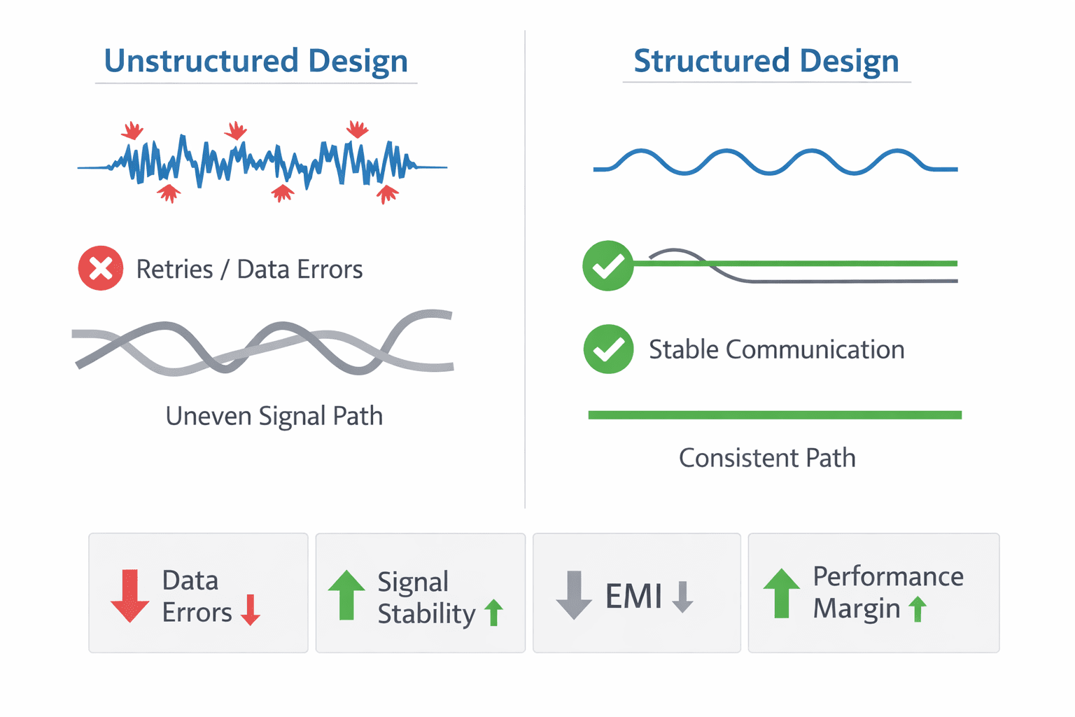
After tightening board-to-board signal discipline, we saw reduced data errors, with intermittent communication failures and retries significantly reduced. Improved signal stability, with waveforms becoming cleaner with less ringing and distortion. Better high-speed performance margins, with interfaces operating reliably closer to their maximum rated speeds. Lower EMI emissions, from cleaner return paths reducing unintended radiation. And more predictable system behavior, with performance consistent across temperature and operating conditions. These improvements weren't visible in schematic diagrams. They were visible in system reliability.
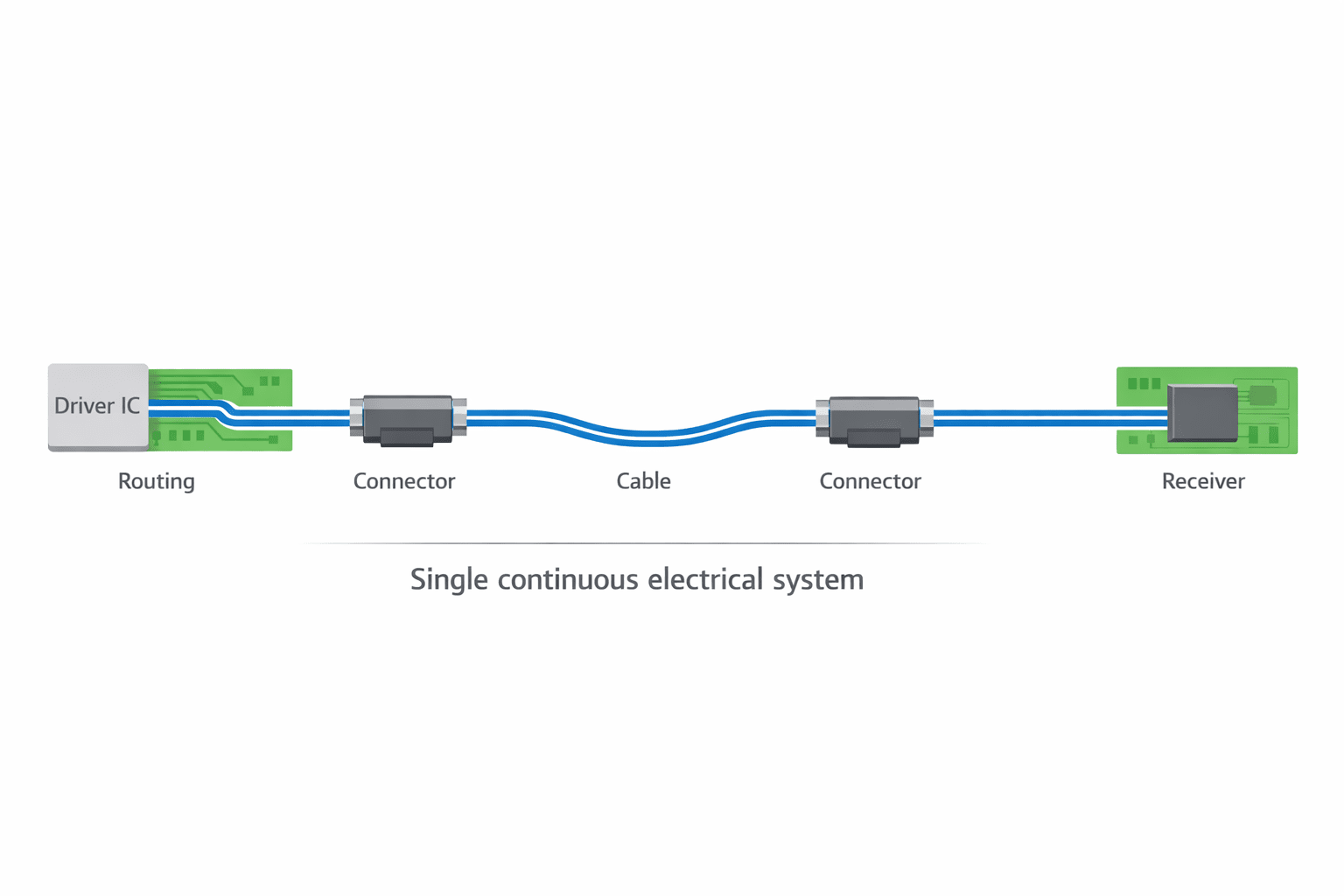
Designing the signal path as a continuous system
A key shift in our methodology: we don't design signals per board, we design signals per system path. That means source driver characteristics, PCB routing, connector behavior, cable or flex interface, and receiving end characteristics all considered as a single chain. This approach avoids local optimization that fails globally.
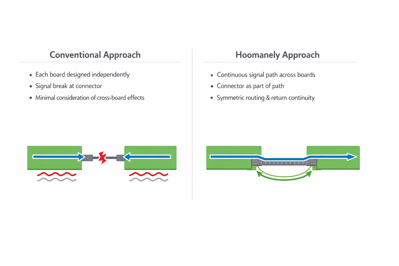
Conventional vs structured high-speed design
The conventional approach optimizes routing within each PCB, assumes connectors behave ideally, and treats boards independently. The Hoomanely approach designs the entire signal path across boards, treats connectors as active signal elements, enforces pair integrity across boundaries, maintains return path continuity, and eliminates stubs across the system. The difference isn't visible in layout screenshots. It's visible in system stability.
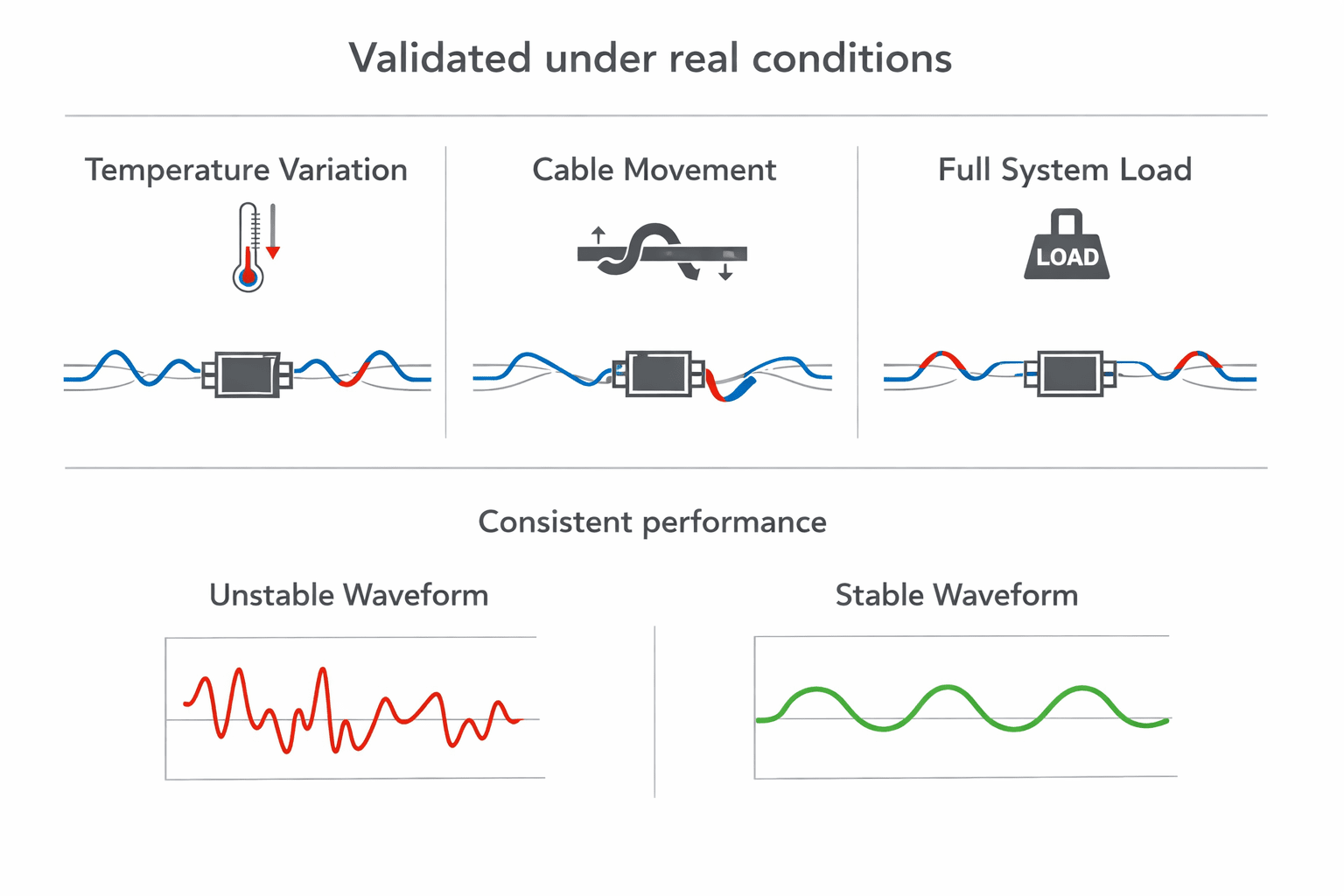
Designing for real conditions, not ideal conditions
High-speed signals behave differently in real environments, temperature changes affect materials, connectors age and wear, cable positioning changes coupling, and power noise varies under load. If the system only works under ideal lab conditions, it isn't robust. We validate across temperature ranges, under full system load, with cable movement, and across production variation, because high-speed integrity must hold under all conditions, not just best-case scenarios.
The core principle
A high-speed signal does not belong to a board. It belongs to a path. That path must remain consistent from source to destination, across every transition, connector, and interface. Once this is understood, design decisions become clearer, connectors are chosen differently, pin assignments become deliberate, routing becomes symmetrical, debug stubs are minimized, and return paths are preserved. The system stops being a collection of boards. It becomes a continuous electrical structure.
Final thought
High-speed issues are rarely dramatic. They're quiet, intermittent, and difficult to trace. That's what makes them dangerous. A system that "mostly works" is often one where signals are just barely holding together across boundaries. At Hoomanely, we design those boundaries deliberately. Because keeping signals clean across board-to-board links isn't about pushing performance limits. It's about removing uncertainty. And in embedded systems, removing uncertainty is what turns a working prototype into a reliable product.



