
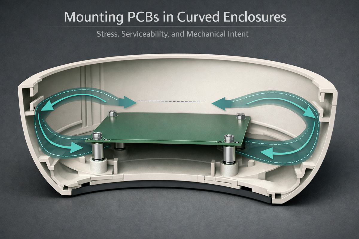
Mounting PCBs in Curved Enclosures: Engineering for Stress, Serviceability, and Longevity
Flat PCBs prefer flat worlds. Curved enclosures do not offer that luxury. In products like our bowl, industrial design demands organic forms, continuous curves that feel natural in the hand, integrate seamlessly into living spaces, and support fluid interaction. But behind that curvature sits a rigid PCB populated with silicon, copper, and solder joints that are fundamentally intolerant of mechanical ambiguity.
Mounting electronics inside curved enclosures is not a packaging exercise. It's a structural engineering problem where stress paths, tolerances, and service access determine whether a product remains stable over years of use, or slowly accumulates invisible mechanical fatigue. At Hoomanely, we approach curved-enclosure mounting as a co-design discipline:
- The PCB
- Enclosure
- Fasteners
- Harnesses are engineered as a single mechanical system
Curvature changes the stress model
In flat enclosures, mounting forces distribute symmetrically. In curved enclosures, forces resolve along arcs. This changes everything, screw preload vectors are no longer perpendicular to the PCB, enclosure flex introduces tangential stress, local curvature amplifies tolerance stack-up, and thermal expansion follows non-linear paths.
A PCB mounted into a curved shell is never purely "at rest." It's always negotiating between its own planar rigidity and the enclosure's geometric intent. Recognizing this early is essential. The mistake is to treat the PCB as the primary structure and the enclosure as a cosmetic shell. In curved products, the enclosure is the structure, and the PCB must be mounted in a way that respects that reality.
Design principle: the PCB must never be forced to conform
A rigid PCB should never be bent to fit curvature. Instead, curvature is absorbed by stand-offs, floating constraints, controlled contact points, and compliant interfaces. For bowl-class products, our PCB mounting strategy ensures the PCB remains mechanically planar, all curvature is resolved in the enclosure geometry, and no mounting operation induces torsion or bowing. This starts with a simple rule: the PCB outline is optimized for clearance, not contact. The board never traces the enclosure wall. It lives inside it.
Mounting architecture: decoupling shape from structure
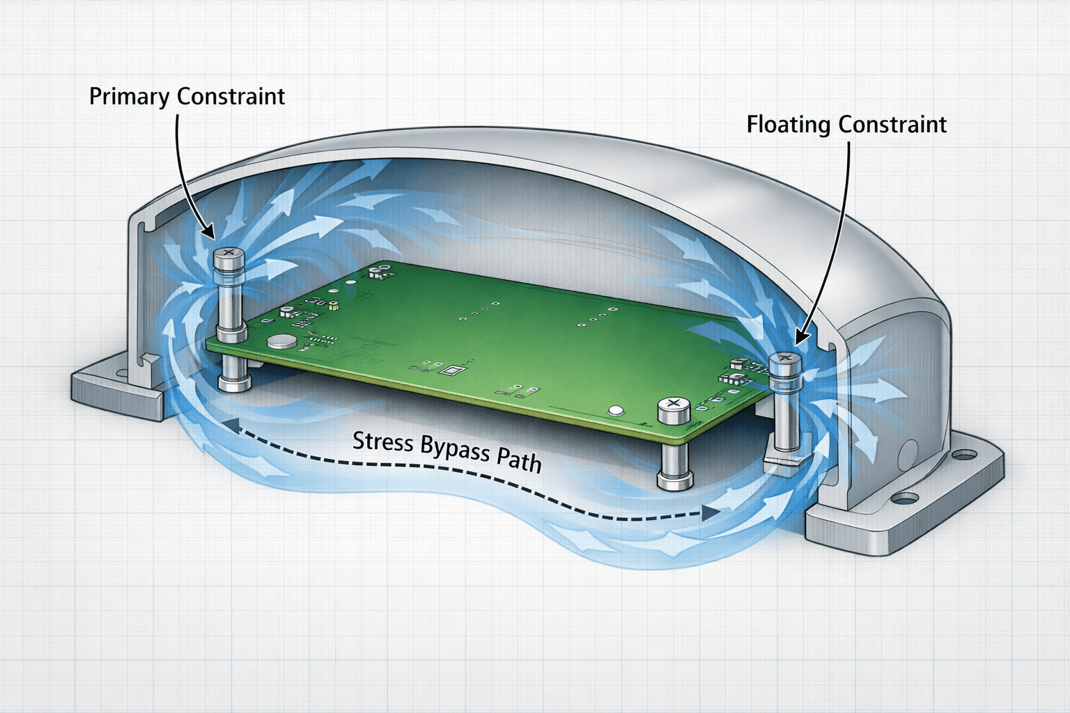
In curved enclosures, over-constraining a PCB is the fastest way to inject stress. Rather than fixing the board rigidly at every available point, we design mounting schemes that fully constrain position, partially constrain rotation, and allow controlled micro-compliance.
Most bowl assemblies use a three-point primary mounting strategy, where two points define the plane, one point defines the reference, and secondary features provide guidance, not force. This ensures no stress from enclosure flex, no tolerance-induced warp, and stable alignment across temperature and time.
Stand-offs are not spacers, they're mechanical interfaces. In curved products, stand-offs are height-tuned to maintain planar PCB alignment, positioned to avoid high-curvature zones, and designed with fillets to reduce stress concentration. We avoid sharp transitions between stand-off and enclosure. Rounded bases distribute load, while controlled compression limits screw-induced strain. Every stand-off location is chosen based on stress flow, not convenience.
Design principle: mounting must survive human interaction
Products like bowls are handled, moved, cleaned, and occasionally bumped. These actions introduce real-world loads that don't appear in CAD. We design mounting systems assuming repeated lifting and placement, surface vibrations, minor impacts, and uneven support during handling. This translates into no cantilevered PCB edges, no mounting points near thin enclosure walls, and no reliance on friction alone. The PCB should feel mechanically "quiet" even when the enclosure experiences motion.
Thermal expansion in curved volumes
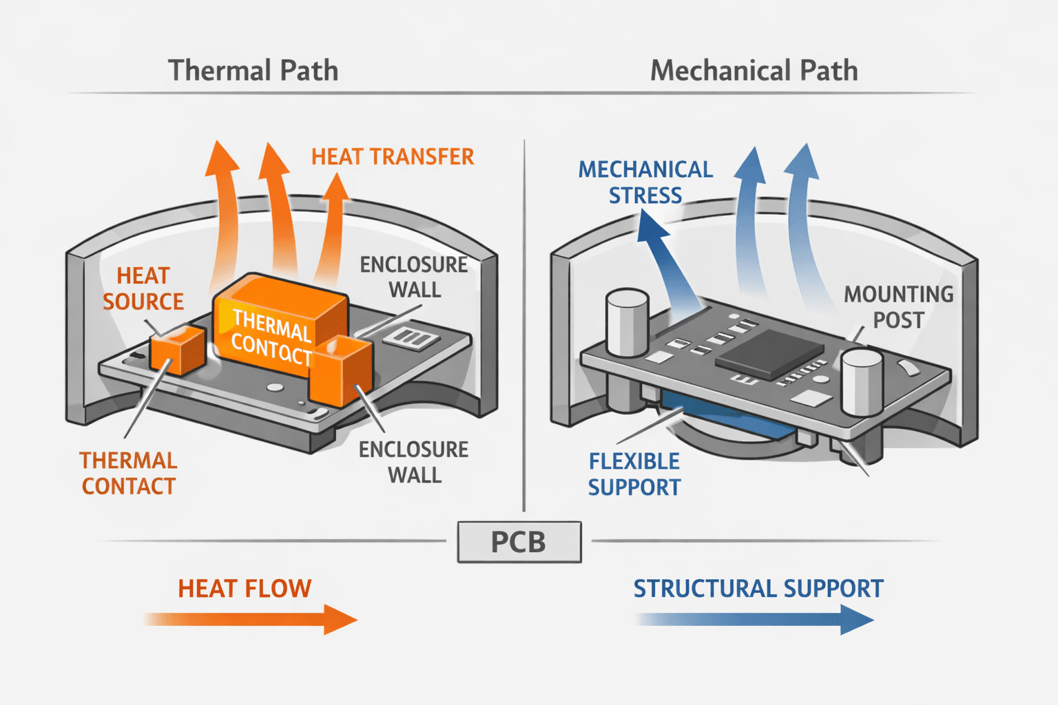
Curved enclosures expand differently than flat ones. As temperature changes, plastic shells expand radially, metal inserts expand axially, and PCBs expand minimally and anisotropically. If these expansions are rigidly coupled, stress accumulates at screw joints, copper planes, and BGA solder balls.
To prevent this, our designs incorporate slotted mounting holes in secondary locations, isolated metal inserts, and defined slip planes between PCB and enclosure. Thermal motion is expected, and engineered for, not resisted.
Design principle: serviceability is a mechanical requirement
A product that cannot be serviced without inducing stress is not serviceable. In curved enclosures, access angles matter. A PCB that can be mounted easily may still be impossible to remove cleanly. Our serviceability requirement is simple: a technician should be able to remove the PCB without bending it.
To enable this, PCBs are oriented for linear extraction paths, harnesses disconnect before PCB removal, no mounting screw requires angled tools, and no clip requires enclosure flex to release. Curvature never blocks service motion. Screw selection is part of stress design too, thread-forming screws are avoided near PCBs, metal inserts are used where repeat service is expected, and torque limits are defined and tested. Fasteners should clamp, not distort.
Harness integration without load transfer
In bowl-class products, harnesses often follow curved paths. If unmanaged, they become unintended structural members. We explicitly prevent harnesses from pulling on PCB connectors, applying torque during enclosure closure, or acting as springs during thermal cycling. This is achieved through harness strain relief before PCB termination, defined service loops, and connector orientation aligned with natural cable exit paths. The PCB should never "feel" the harness.
Vibration and long-term fatigue
Curved enclosures tend to amplify certain vibration modes, which can quietly fatigue solder joints or mounting interfaces over time. To counter this, PCB mass is centrally supported, high-mass components are aligned with mounting points, and enclosure ribs are placed to damp, not reflect, vibration. Mechanical energy should flow around the PCB, not through it.
Material pairing: PCB and enclosure as a system
Material choice is not independent. For curved enclosures, we evaluate CTE mismatch between PCB and shell, local stiffness gradients, and insert materials and their expansion behavior. In bowls, where plastics dominate, we design PCBs assuming the enclosure will move more than the board, contact points must accommodate that motion, and rigid coupling is the enemy of longevity. This mindset prevents stress from ever accumulating in solder or copper.
Validation beyond fit
A PCB that fits is not necessarily safe. Our validation focuses on stress under assembly torque, stress during enclosure flex, stress during removal and reinstallation, and stress after thermal soak. The success metric is not the absence of cracks, it's the absence of preload memory. After removal, the PCB should return to a neutral state.
Conclusion: curvature demands mechanical intent
Mounting PCBs in curved enclosures is not about clever tricks or compensating for industrial design. It's about accepting curvature as a first-class mechanical constraint and designing electronics that coexist with it gracefully. At Hoomanely, we don't ask PCBs to tolerate stress, we engineer systems where stress never accumulates. Through controlled constraints, compliant interfaces, and service-first thinking, our curved products like the bowl achieve both elegance and durability.
This is not a compromise. It's precision applied where geometry and mechanics intersect. When enclosure curvature, PCB rigidity, and human interaction are treated as a single system, the result is hardware that not only works, but stays trustworthy, serviceable, and stable over time.



