
Protection by Design: Engineering Reliability Into Every vBus Module
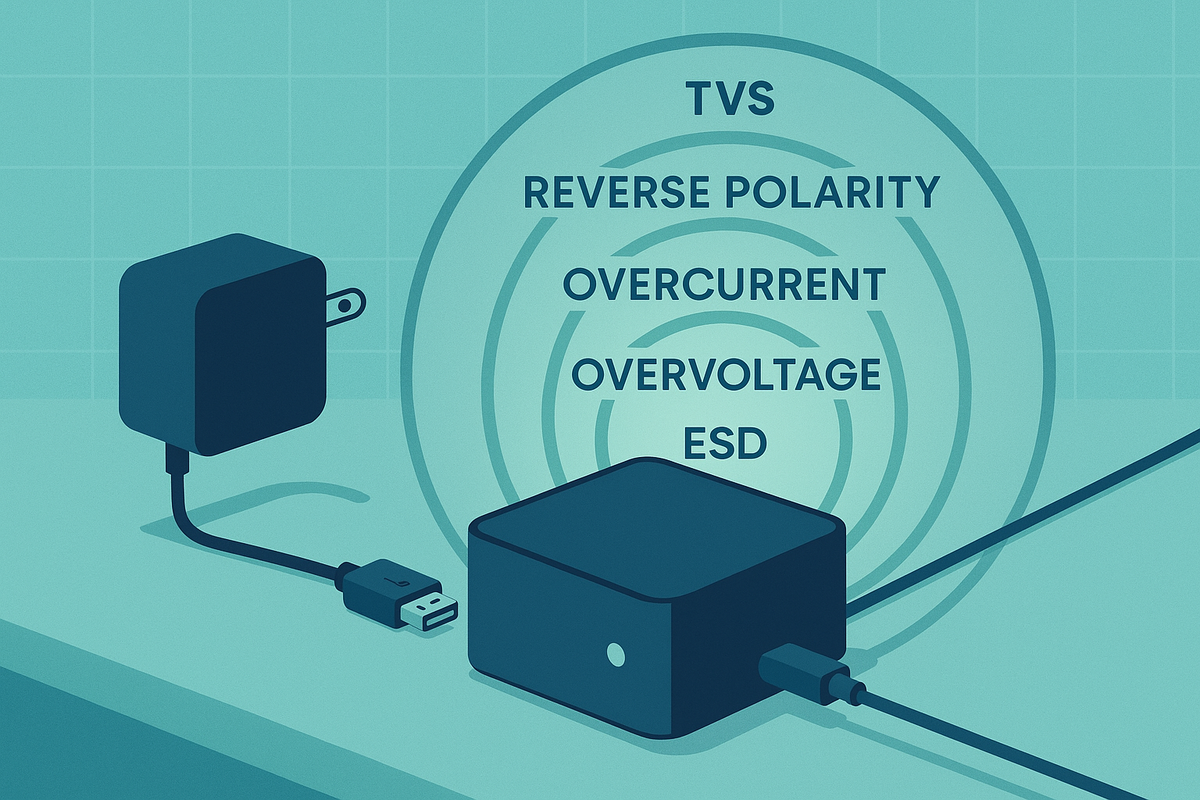
At Hoomanely, we design consumer products for real-world home and office environments, where power adapters vary in quality, USB cables get swapped between devices, and static electricity from carpets is an everyday occurrence. Our vBus modular architecture thrives in these conditions through a deliberate design philosophy: comprehensive protection circuits are mandatory, not optional.
Transient voltage suppression: the first line of defense
Transient voltage events, brief high-energy voltage spikes, occur constantly in everyday consumer electronics, from power adapters switching off to USB hotplugging to coupled noise from adjacent devices. Every connection point that leaves a module receives TVS diode protection, USB ports, communication connectors, and sensor inputs all include dedicated TVS diodes rated for their specific voltage and energy levels. Communication lines on vBus connectors, particularly CAN_H, CAN_L, and differential pairs, include bidirectional TVS diodes clamping voltage excursions above safe levels. Input power lines incorporate TVS diodes protecting against transients from switching power adapters common in consumer electronics.
Component selection targets a clamping voltage with 10-20% margin below the absolute maximum rating of protected ICs, peak pulse power adequate for expected transient energy (commonly 400-600W for signal lines), low enough capacitance to avoid signal degradation on high-speed interfaces like USB, and sub-nanosecond response time. TVS diode effectiveness depends heavily on placement, we position them immediately adjacent to connector pins, before any traces route signals into the circuit, minimizing the impedance path between the transient source and the protection device.
Polarity protection: foolproof power connections
Power supply connections are inherently vulnerable to human error, users might connect generic power adapters with swapped polarity, or damaged cables create unexpected voltage paths. Our preferred implementation uses a P-channel MOSFET in the high-side power path with its body diode reverse-biased. When voltage is applied correctly, the MOSFET conducts with a minimal 50-150mV drop at rated current. When reversed, the body diode blocks current flow, preventing damage, with low forward voltage drop preserving efficiency, no continuous power dissipation, and automatic reset when correct polarity is applied. For lower-power interfaces or cost-sensitive designs, we use series Schottky diodes instead, dissipating more power but offering simplicity and reliability for secondary power inputs.
The vBus architecture itself provides inherent polarity protection through intelligent pin allocation, power and ground pins physically separated on the connector making reverse insertion mechanically impossible for keyed connectors. For non-keyed connectors, we implement the MOSFET protection scheme on each SoM's power input stage.
Overcurrent protection: guarding against short circuits
Overcurrent events occur when load impedance drops below expected values, short circuits in damaged cables, failed components, or accidental contact with conductive materials. Electronic fuses monitor load current and disconnect power when thresholds are exceeded, automatically resetting after the fault clears, unlike traditional fuses that must be physically replaced. Key features include a programmable current limit, fast microsecond-to-millisecond response, retry logic, fault indication output, and low on-resistance during normal operation. For individual subsystem control, we use high-side power switches with integrated current limiting, each peripheral SoM or power domain has its own protected supply, preventing a fault in one module from affecting others.
Critical power rails include dedicated current sense amplifiers continuously monitoring consumption, feeding into the system processor for real-time power budgeting, predictive fault detection from gradually increasing current, usage analytics, and fault diagnostics identifying which rail exceeded limits. The vBus Power SoM implements multi-channel overcurrent protection with independent current limiting on each voltage rail, so if a connected SoM develops a short circuit, only that module's power gets disconnected, the rest of the system continues operating.
Overvoltage protection: input voltage range management
Input voltage can exceed specifications due to power adapter faults, misconfigured bench supplies during development, or incorrect power adapters. Simple protection uses Zener diodes or TVS diodes in breakdown region across the power rail, conducting and clamping voltage above the breakdown threshold. More sophisticated voltage supervisor ICs compare input voltage against precision references, asserting a reset signal, disabling downstream converters, and generating fault indication when overvoltage is detected. Many modern regulators include built-in overvoltage lockout that prevents operation beyond safe limits, and where possible we design power supplies with reasonable input voltage tolerance, accommodating adapter variation without triggering protection circuits unnecessarily.
Undervoltage protection and brown-out handling
Undervoltage conditions, where voltage drops below minimum operating specifications, occur with low-quality power adapters or when multiple high-current devices share a source. Processors operating below specified voltage may execute instructions incorrectly, corrupting memory or configuration data. Voltage supervisors monitor each critical rail against precision references, asserting a reset signal that holds the processor in reset during undervoltage, then automatically releasing when voltage recovers to safe levels. Hysteresis of 50-100mV prevents oscillation when voltage hovers near the threshold. In multi-rail systems, power-good signals from each regulator chain together, ensuring downstream regulators don't start until upstream supplies are stable.
ESD protection: human interface hardening
Any user-accessible interface, buttons, connectors, USB ports, touchpoints, requires ESD protection to handle static discharge events that can reach 8-15kV in low-humidity environments, common in heated homes during winter. Multi-channel ESD protection ICs at connector pins offer ultra-low capacitance preserving signal integrity and sub-nanosecond response times shunting ESD energy to ground. TVS diodes serve a dual purpose of transient voltage suppression and ESD protection, selected to meet IEC 61000-4-2 immunity requirements. Layout matters too, wide low-impedance ground connections from ESD devices to the ground plane, protection devices placed immediately at connector pins before any signal routing, and ground plane continuity under connectors.
USB ports are particularly vulnerable since users frequently plug and unplug cables, so our standard USB protection includes dedicated USB ESD protection ICs protecting D+, D-, VBUS, and GND, with capacitance under 3pF to maintain USB 2.0 High-Speed signal integrity, integrated with TVS diodes for combined ESD and overvoltage protection.
Standardized protection across vBus modules
Each SoM category has tailored protection requirements. CPU SoMs get polarity protection, overvoltage clamping, and overcurrent limiting on input power, dedicated USB ESD protection ICs, TVS diodes on communication interfaces, and ESD protection on debug ports. Power SoMs get TVS diodes for adapter transient protection, overcurrent protection per output channel, transient-immune enable signals, and overtemperature shutdown on regulators. Peripheral SoMs get TVS protection on analog sensor inputs, ESD diodes on digital interfaces, and the full protection suite on the vBus connector. Communication SoMs get integrated USB protection with data line ESD protection, TVS diodes on antenna connections, and TVS protection on exposed wired communication signal lines.
Protection circuits are mandatory checklist items in our design review process, covering TVS or ESD protection on all external interfaces, polarity protection on power inputs, overcurrent limiting per rail, voltage supervisors on critical rails, dedicated USB ESD ICs, verified device ratings, and layout best practices.
Testing and validation
Every design undergoes validation:
- A reverse polarity test applying reverse voltage and verifying no damage
- An overvoltage stress test at 20% above maximum rating verifying protection circuits activate
- ESD testing per IEC 61000-4-2 at ±4kV to ±8kV on all user-accessible points
- A short circuit test verifying current limiting engages and recovers cleanly
- Repeated USB hotplug cycling under various conditions
Real-world protection scenarios
Users often substitute power adapters from other devices, our wide input range and overvoltage protection handle the variation. Connecting high-current USB devices or damaged cables triggers overcurrent protection, protecting both the product and the connected device. Winter conditions create high ESD potential from carpets, our ESD protection handles discharge events seamlessly. Worn or damaged cables creating intermittent shorts get detected and responded to automatically. And vBus modularity encourages module swapping during development, protection circuits handle the inrush currents and transients associated with hot-plug events.
Conclusion: defense in depth for consumer reliability
Our protection circuit policy reflects a fundamental design philosophy: consumer products must handle real-world usage patterns gracefully. Every vBus module incorporates multiple layers of protection, polarity, transient, overcurrent, overvoltage, undervoltage, and ESD, creating defense in depth that ensures reliable operation in diverse home and office environments.
The modest cost of protection circuits, typically adding just a few dollars to module BOM, pays dividends through reduced support costs, enhanced product longevity, and customer confidence in system robustness. As our vBus ecosystem expands into new consumer applications, our protection circuit standards evolve with it, but the core principle remains constant: protection by design, not as an afterthought.



