
Quick-Connect Reliability: Modular Harnesses in the vBus Ecosystem
At Hoomanely, we design products for the real world, environments where systems occasionally need service, where components eventually reach end-of-life, and where rapid repair directly impacts operational uptime. Our vBus modular architecture extends beyond PCB-level modularity into a complete system philosophy that includes intelligent wire harness design. The result: field-replaceable interconnects that enable roughly 5-minute module swaps instead of hour-long teardown procedures.
Modular harnesses aren't just cables with connectors, they're carefully engineered assemblies that segment electrical interconnects into replaceable units, standardize connection interfaces, and embed identification directly into the physical hardware.
The traditional harness problem
Traditional product wiring creates real service challenges. Point-to-point wiring means unique wire lengths for each product configuration, complex routing, and difficulty reproducing exactly during repair. Integrated harnesses mean replacing one wire requires replacing the entire harness, diagnosing a connection issue means testing every wire, and a module swap requires complete harness disconnect and reconnect with high risk of misconnection during reassembly.
These factors compound into significant service downtime:
- Diagnosis running 20-40 minutes to identify a failed connection
- Disassembly running 30-60 minutes to remove covers and route the harness out
- Replacement running 15-30 minutes to install and route a new harness
- Testing running 10-20 minutes to verify all connections
Total: 75-150 minutes per service event.
The vBus modular harness philosophy
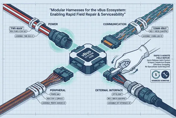
We divide harness assemblies into functional segments aligned with vBus module boundaries. Power harnesses connect the Power SoM to system power input, with a dedicated power connector at the module, independent of signal routing, with quick-disconnect at both ends. Communication harnesses link modules within the vBus ecosystem via standardized pinout, color-coded by function, with keyed connectors preventing misconnection. Peripheral harnesses connect Peripheral SoMs to external sensors and interfaces, matched to peripheral function and labeled with peripheral type and port assignment. External interface harnesses handle user-facing connections like USB, Ethernet, power jack, and button or LED interfaces.
The benefit: isolate service to the affected subsystem. Power issue? Replace the power harness only. Communication problem? Swap the communication harness. No need to disturb unaffected interconnects.
Standardized connector interfaces
Each harness terminates in a vBus-compliant connector, 16, 40, 50, or 100-pin depending on module type, pin-compatible across product variants, keyed to prevent reverse insertion, with a locking mechanism ensuring secure connection. Where possible we use industry-standard external connectors, USB Type-A and Type-C, RJ45, barrel jack or terminal block, JST-XH or Molex PicoBlade. Custom connectors only appear when necessary, Anderson Powerpole for high-current power above 5A, SMA or U.FL for RF, M12 circular connectors for specialized industrial protocols.
Every connector physically prevents incorrect insertion through asymmetric shell design, pin-1 indicators, polarized latches, and color coding for additional visual confirmation.
Cable identification system
Every harness is clearly labeled at both ends, including harness type (like PWR-MAIN or COMM-VBUS), product and module compatibility, connector type, revision, and part number. Labels use heat-shrink printed labels or cable-wrap tags, durable against abrasion, chemicals, and temperature, permanent against fading or peeling, positioned at the connector end for visibility when installed. Wire color coding follows a consistent scheme: red for positive power, black for ground return, yellow for 3.3V power, blue for communication data lines, green for I2C or low-speed control, white or gray for general-purpose signals.
Rapid repair workflow
Modular harnesses simplify troubleshooting through segment isolation, systematically testing each harness, power presence at the module connector, data activity LED for communication, sensor output validity for peripherals. Connector verification through visual and mechanical inspection catches bent pins, broken latches, or broken wires at crimp points. Swap testing with a spare harness set on hand is often the fastest diagnostic method. Diagnosis time drops to roughly 5-10 minutes versus 20-40 minutes tracing an integrated harness.
Replacement needs minimal tools, most connectors are hand-detachable, some need a small flathead screwdriver, none need soldering or crimping. The procedure: power down the system, disconnect the failed harness by identifying it via the label and releasing the locking mechanism, route the new harness along the same path maintaining bend radius, connect it with orientation verified and the latch clicked, then power on and test the affected function. Replacement time: roughly 3-5 minutes per harness versus 30-60 minutes for an integrated harness.
Service manual integration documents harness replacement procedures with exploded-view diagrams, connector location photos, step-by-step instructions, and troubleshooting decision trees. Short tutorial videos demonstrate connector release techniques, proper routing paths, and verification testing. Training requirements drop from 4-8 hours per product for traditional harness routing down to 30-60 minutes of general training on connector types and the labeling system, an 80-90% reduction in product-specific training time.
Design for manufacturability
Component sourcing draws from standard connectors from major suppliers like Molex, JST, TE Connectivity, and Amphenol, globally available with short lead times. Cable selection is application-appropriate, AWG size based on current, insulation rated for the environment, shielding where needed for CAN bus or high-speed data. Assembly uses crimp termination for most connections, IDC for ribbon cables and high-density connectors, and soldering only for specialty connections rarely needed. Every harness is tested for continuity, insulation resistance, pull test integrity, and hi-pot dielectric strength for high-voltage harnesses.
Each harness has a dedicated BOM as a sub-assembly, with an independent part number and referenced assembly instructions. Product variants use different harness combinations tracked through the BOM system by SKU. Common harnesses like power and main communication get higher stock levels, specialty product-specific peripherals get lower stock, enabling rapid field service through overnight replacement shipping.
Reliability and testing
Connectors are rated for repeated mating, industrial connectors typically 500-1000 insertion cycles, high-reliability connectors 5000-plus cycles for military or aerospace grade, selected based on expected service frequency. Field service expectations for consumer products run 5-10 years with 3-5 service events expected, and connector life far exceeds expected usage. Validation testing runs 50-100 connect and disconnect cycles with continuity tested after each cycle and connector wear inspected visually.
Strain relief prevents wire fatigue at the connector interface through overmolded strain relief, heat-shrink tubing, and cable ties securing to the structure near the connector. Vibration resistance comes from positive latch mechanisms and secondary retention, validated through vibration testing where applicable. Moisture protection scales to the deployment environment, from standard connectors for indoor products up to IP67/IP68 for submersion protection.
Cost-benefit analysis
The modular harness approach requires upfront engineering for connector selection, harness routing design, labeling system development, and documentation. Manufacturing costs run slightly higher per unit, connectors cost more than direct solder connections, plus assembly labor and labeling materials, typically adding $5-15 per product depending on harness count and connector types.
Real-world deployment success
Field service metrics show the payoff. Time to resolution drops from 90-120 minutes with traditional integrated harnesses to 15-25 minutes with modular harnesses, a 75-85% improvement. First-time fix rate improves from 75-85% with traditional harnesses, hurt by misconnections and routing errors, to 95-98% with modular harnesses thanks to keyed connectors and clear labeling. Technician feedback reports higher confidence, reduced frustration, and faster certification.
Minimized downtime matters for commercial deployments, industrial monitoring drops from hours to minutes, commercial installations can service during off-hours, and laboratory equipment sees rapid restoration of test capability. Some customers even perform their own repairs, since clear labeling enables non-technical users to identify harnesses and simple connectors don't require specialized tools.
Conclusion: modularity beyond the PCB
Modular harness design exemplifies our vBus philosophy extended into every aspect of product architecture. By segmenting interconnects into functional, field-replaceable assemblies with standardized interfaces and clear identification, we've transformed service from a complex procedure into a straightforward operation.
The benefits cascade through the entire product lifecycle:
- Faster development through reused harness designs
- Simpler manufacturing through modular assembly
- Reduced service costs through rapid repair
- Improved customer satisfaction through minimal downtime
As our vBus ecosystem scales and products deploy globally, modular harnesses ensure serviceability remains excellent regardless of location or technician experience level. When a system needs repair, the difference between 15 minutes and 2 hours is the difference between minor inconvenience and significant operational disruption.



