
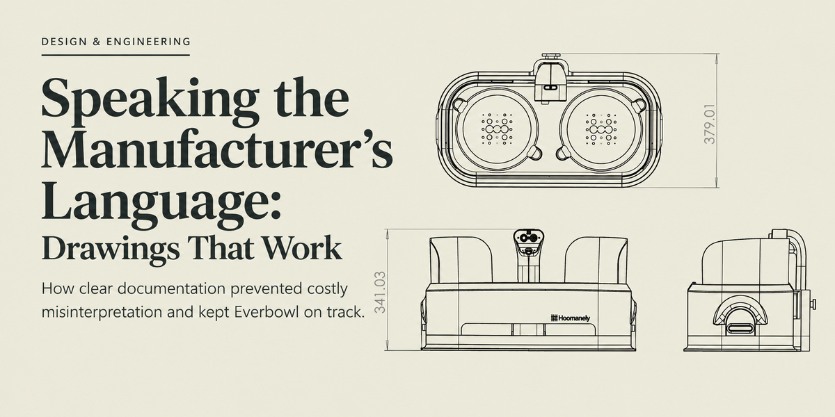
Speaking the Manufacturer's Language: Drawings That Work
How clear engineering documentation prevented costly misinterpretation while taking Everbowl from design files to physical hardware.
Introduction
A CAD model shows what a part looks like. A manufacturing drawing has to communicate what the part actually needs to be. That difference mattered more and more as we moved Everbowl from internal design iterations to parts made by outside vendors, because the moment a drawing leaves the design team, the person who made it isn't there to explain every feature, dimension, tolerance, material, or finish requirement.
A manufacturer reads a drawing looking for practical answers: what do I make, how accurately, out of what material, which surfaces actually matter, and what can I inspect once it's done? For us, improving our drawings was never about making documentation look more polished. It was about closing the gap between our design intent and the physical part that came back from a supplier.
The problem: CAD intent doesn't automatically become manufacturing intent
Early in prototyping, you can get away with incomplete documentation. A designer sends a STEP file, hops on a call, and points at a feature: "this hole needs to align with the load cell," or "this surface needs to sit flush against the ring." That works fine with five parts and everyone in the same room.
It stops working once you scale up. As Everbowl moved toward larger builds, we were juggling multiple manufacturing processes at once, including FDM, SLA, vacuum casting, and laser-cut aluminum. Each process reads geometry differently, and every specification we left out was one more chance for someone downstream to guess. The actual bottleneck wasn't manufacturing capability. It was communication bandwidth. A drawing has to carry the design intent on its own, without a phone call to back it up.
What a manufacturer actually needs to know
A useful drawing answers five questions: what is the part, what material is it made from, what dimensions actually matter, what tolerances are acceptable, and what condition should it arrive in?
For Everbowl, that mattered because different parts had very different requirements. An external housing could tolerate some dimensional drift on a purely cosmetic feature. A load-cell mounting interface couldn't. So the drawing had to make clear where precision actually mattered and where it didn't, which turned out to be one of the more important principles in writing documentation that's actually usable.
Dimensions are not all equal
One of the easiest mistakes is dimensioning everything with the same precision. A hole might read Ø5.00 ± 0.05 mm right next to another feature that's just "100 mm." That's not a problem on its own, but the manufacturer needs to understand why the difference exists.
For Everbowl, dimensional requirements followed function. The aluminum rings interacting with the load cells needed tight control because their relationship set the mechanical load path. Certain housing dimensions, on the other hand, were mostly about fit and looks. That pushed us toward a simple rule: critical interfaces get tighter control, general enclosure geometry gets a reasonable manufacturing tolerance, and cosmetic features get controlled appearance rather than precision they don't actually need. That's what keeps you from making every dimension "perfect" and accidentally pricing the whole part out of reach.
Drawing the interfaces, not just the parts
The most useful dimensions are usually the ones that describe how one part relates to another, not just its own shape. Take the load-cell assembly: a top aluminum ring supporting the bowl, a load cell between the rings, a bottom ring attached to the body, fasteners holding the stack together, and plastic housing around the whole thing.
A drawing that only documents each part's own dimensions isn't enough. The real question is whether these parts will actually assemble into the load path they're supposed to form, which means the dimensions around mounting holes, interfaces, thicknesses, offsets, and alignment features matter a lot more than the ones describing overall shape.
From "looks correct" to "can be inspected"
Another lesson: a requirement is only useful if someone can actually check whether the part meets it. Saying "hole should be aligned" isn't a real engineering requirement, because a manufacturer can't reliably inspect "aligned" unless the drawing defines what that means. It could be a hole position, a datum reference, a positional tolerance, center-to-center dimensions, or a feature pattern, depending on the part and the process.
The underlying rule is simple: if a feature actually matters to function, the drawing needs to give a measurable way to verify it. That matters even more once you're producing more than one unit. The first part might fit through luck. A real spec is what determines whether the next 24 parts fit too.
When more detail actually makes a drawing worse
More information doesn't automatically mean a better drawing. A sheet with hundreds of dimensions gets hard to read fast, and that's exactly when misinterpretation creeps in. This is where thinking about design intent as a hierarchy helps: primary information (overall dimensions, material, process, critical interfaces), secondary information (general dimensions, hole patterns, assembly features), and supporting information (surface finish, cosmetic requirements, notes, inspection requirements).
A manufacturer should be able to find the important requirements without digging through a wall of annotations. This mattered even more for us since our parts came out of different processes, and a dimension that made sense on a machined component didn't always mean the same thing on a laser-cut sheet part or a cast plastic one.
Standardization reduced questions
As the number of manufactured parts grew, we found another opportunity: standardizing the documentation itself rather than building every drawing from scratch. That meant keeping units, dimension formatting, tolerance conventions, material descriptions, revision info, drawing numbers, finish specs, critical-feature notation, and general notes consistent across every drawing.
It wasn't about making things look uniform for its own sake. It was about cutting down cognitive load. Once a supplier understands how one Everbowl drawing communicates material, tolerance, revision, and finish, the next one shouldn't force them to learn a new language from scratch.
Measuring documentation quality
It helps to treat documentation as something you can actually measure, not just something you write.
RFQ clarity score: a simple internal check for whether an RFQ package has everything manufacturing needs. Roughly, required information correctly specified divided by total required information, times 100. The exact scoring can flex to whatever fits your process, but the important part is applying it consistently. A package with the right CAD, drawing, material, finish, quantity, critical tolerances, revision, and inspection requirements should score higher than one that leaves half of that to interpretation.
Manufacturing error rate: manufacturing-related discrepancies divided by total parts manufactured, times 100. Not every error traces back to documentation. Machine setup, material variation, operator error, and process capability all play a role too. But if the same kind of mistake keeps showing up across suppliers or batches, it's worth checking the documentation first.
Engineering insight: A drawing isn't finished when the designer understands it. It's finished when a manufacturer can make and inspect the part without ever needing the designer to explain what it means.
What changed for Everbowl
As the product matured, our documentation shifted from describing geometry to protecting interfaces. Everbowl uses several materials and processes at once: ABS and PLA for printed parts, cast polymer from vacuum casting, SLA where finer geometry was needed, 2 mm and 2.5 mm aluminum sheet, threaded inserts for repeatable joints, and painted surfaces across the assembly.
Each process brings its own considerations. A laser-cut aluminum ring gets specified very differently from a vacuum-cast enclosure, and a threaded insert location carries a different functional weight than a purely cosmetic surface. The drawings became the way we translated the product's architecture into something a supplier could actually build.
A small drawing error can become a system error
This is probably the most important lesson. Say a mounting hole sits slightly off from where it's supposed to be. On its own, that displacement might look totally acceptable. But it can still cascade: hole variation leads to assembly misalignment, which leads to uneven joint loading, which stresses the component, which shifts sensor geometry, which shows up as a real performance change at the system level.
The drawing sits right at the start of that chain, which is exactly why documentation isn't administrative work. It's part of the product's technical architecture. The same logic applies to tolerances: if two mating parts each carry ±0.5 mm variation, their worst-case combined variation can approach 1 mm. That might be irrelevant on a decorative seam and completely unacceptable on a precision mechanical interface. The drawing is where those assumptions get made explicit, one way or the other.
Common mistakes we learned to avoid
- Relying on the CAD model alone. A 3D model shows geometry, but it rarely carries enough manufacturing intent by itself.
- Over-tolerancing everything. Tight tolerances add cost and difficulty. Precision should follow function.
- Leaving out material specifications. "Aluminum" or "plastic" alone isn't enough once grade, thickness, or mechanical behavior actually matters.
- Ignoring finish requirements. Painting, texture, coating, and surface prep can change the final part as much as its geometry does.
- Burying the critical interfaces. The dimensions that actually matter often get lost among dozens that don't.
- Losing control of revisions. A perfect drawing is worthless if the supplier builds from an outdated one.
From engineering intent to physical product
The deeper lesson from Everbowl was that engineering communication is itself a design problem. A mechanical design exists in several forms at once: CAD, drawing, RFQ, manufactured part, assembly, product. Every step between those forms is a chance for information to get lost. A good drawing is what keeps that loss to a minimum.
The goal was never to describe every last detail of the CAD model. It was to preserve whatever actually matters once the design leaves the engineer's screen and enters a manufacturing process.
How this shows up at Hoomanely
At Hoomanely, we're building hardware that has to hold up outside the environment it was designed in. Everbowl made that obvious: the product was never manufactured by the person who created every CAD feature. It moved through suppliers, processes, materials, finishing, assembly, and inspection.
That's what made documentation part of the product itself. A clear drawing let our mechanical decisions survive that whole journey with less room for misinterpretation. Documentation became another interface, this time between design and manufacturing, and getting that interface right directly strengthened how reliable the product turned out to be.
Key takeaways
- A CAD model shows geometry. A drawing communicates manufacturing intent.
- Critical interfaces deserve more attention than dimensions that don't affect function.
- Every requirement that matters should be measurable or inspectable.
- Tolerances should follow function, not just chase maximum precision everywhere.
- RFQ documentation should leave as little as possible to the manufacturer's assumption.
- Standardized drawing practices cut down on repeated back-and-forth.
- Revision control becomes essential the moment multiple suppliers or batches are involved.
- Documentation quality feeds directly into manufacturing quality.
Conclusion
The best manufacturing drawing isn't the one with the most dimensions on it. It's the one that leaves the fewest open questions. Building Everbowl taught us that the gap between a good design and a good manufactured product is usually filled with small decisions: which dimension is actually critical, which tolerance is necessary, which surface needs protecting, which hole controls alignment, and which requirement needs to be spelled out instead of assumed.
Speaking the manufacturer's language just means turning those decisions into information that can survive without you in the room. The drawing is where engineering intent stops being an idea in your head and becomes something someone else can actually build.



