
The Language of Hardware: How Standardized Schematic Annotation Accelerates Design at Scale
At Hoomanely, our vBus modular architecture isn't just about physical connectors and pin-out standards, it extends deep into how we design, document, and communicate about our systems. One of our most powerful innovations is the standardization of net names across every schematic in our entire product ecosystem.
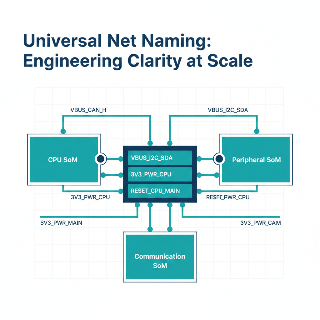
Every signal, every power rail, every connection in our designs follows a rigorous, universal naming convention. Whether you're examining a CPU SoM schematic, reviewing a Peripheral SoM design, or validating a Communication SoM layout, the naming language remains absolutely consistent. "VBUS_CAN_H" means exactly the same thing in every design. "3V3_PWR_CPU" is instantly recognizable regardless of which module you're working on.
The power of naming: why annotation standards matter
Most EDA tools default to auto-generated net names like "Net1" or "N$47." These work technically, the tools can route the PCB, the circuit functions correctly, and production proceeds. But design intent disappears, "N$47" tells you nothing about whether it's power, signal, or what function it serves, you have to trace the net through multiple pages to understand it. Error detection suffers too, when a reviewer sees "3V3_CPU_CORE" connected to a 5V regulator output, alarm bells ring immediately, but "Net47" connected somewhere needs investigation that reviewers might not have time for. Knowledge transfer becomes painful, explaining a design turns into an archaeological expedition. Debugging multiplies in difficulty, since "Net47" on the schematic doesn't help you find the corresponding PCB trace without significant mental mapping. And collaboration slows to a crawl, cross-functional discussions devolve into "the net on page 3, third from the top" rather than clear technical communication.
The vBus naming philosophy: clarity through convention
Every net name answers three fundamental questions:
- What is it (power, signal, control)
- What voltage or logic level
- What purpose or destination
This creates names like "5V_PWR_MAIN" for the main 5V power rail, "I2C_SDA_SENSOR" for the I2C data line to sensors, "CAN_H_BUS" for the CAN bus high signal, and "UART_TX_DEBUG" for the UART transmit line to the debug console.
We use a hierarchical structure mirroring the system architecture. Power nets follow a voltage-type-domain format, like "3V3_PWR_CPU" or "1V8_PWR_IO." Signal nets follow an interface-signal-destination format, like "SPI_MOSI_FLASH" or "UART_RX_GPS." Control signals follow a function-type-target format, like "ENABLE_PWR_PERIPH" or "RESET_CPU_MAIN." Once you understand the pattern, you can decode any net name in our schematics instantly.
Because all our SoMs follow the same connector pin-block structure, the same signals appear with the same names across every design, "VBUS_CAN_H," "VBUS_I2C_SDA," and "VBUS_5V_PWR" mean exactly the same thing whether you're looking at a CPU SoM or a Peripheral SoM. An engineer familiar with one design can immediately understand another, and design reviews become faster because everyone speaks the same language.
Power net annotation: voltage domains made visible
Primary power rails follow clear patterns, "5V_PWR_MAIN" for main system power, "3V3_PWR_DIGITAL" for digital logic, "1V8_PWR_CORE" for processor core power, "12V_PWR_EXTERNAL" for external supply input. Derived and regulated rails get their own naming, "3V3_REG_SENSORS," "5V_REG_USB," "1V8_REG_IO." Ground references are distinguished too, "GND_DIGITAL," "GND_ANALOG," "GND_POWER," "GND_CHASSIS," making ground domain isolation explicit in the schematic itself.
Beyond naming, we annotate power nets with additional information directly on schematics, current budget notes showing typical, peak, and design margin, voltage tolerance callouts showing nominal and acceptable range, and sequencing information showing power-up order and timing. This information transforms the schematic from "here are the connections" to "here's how the system actually operates."
Signal net annotation: interface standards at a glance
For every major communication interface, we maintain consistent naming. I2C buses use a numbered controller suffix plus a location indicator, distinguishing vBus interconnect signals from module-internal ones. SPI interfaces name multiple chip selects by target device, no ambiguity about which device is selected by which signal. CAN bus signals carry the bus number and differential line designation. UART interfaces name the controller number and destination, like "UART1_TX_GPS" for the transmit line to a GPS module.
For high-speed differential pairs, we maintain pair association in naming, USB D+ and D- lines paired explicitly, Ethernet TX and RX positive and negative pairs numbered by MDI pair. The P and N suffix makes differential pairing explicit, and PCB layout tools can automatically route these as coupled differential pairs based on the naming convention alone.
Control and status signals follow their own clear patterns too, reset signals like "RESET_CPU_MAIN" or "RESET_PWR_GOOD," enable signals like "ENABLE_3V3_SENSORS," and interrupt signals like "INT_SENSOR_ACCEL" or "INT_FAULT_POWER." Each category follows its own consistent pattern, making the schematic immediately navigable.
Annotation for programming and debug
Debug interfaces receive special attention, a "DEBUG_" prefix on SWDIO, SWCLK, reset, and UART signals immediately identifies programming and debugging infrastructure critical during bring-up and troubleshooting. Boot configuration signals like "BOOT0_SELECT" and "BOOT_MODE_UART" give clear indication of boot mode selection, helping both during development when you need to force bootloader mode and during production when ensuring correct boot configuration.
The onboarding acceleration effect
When a new engineer joins, day one covers vBus architecture principles and annotation standards with a one-page reference guide. By day two or three, reviewing existing schematics, self-documenting names let them grasp design intent rapidly, questions focus on high-level architecture rather than "what does this net do." By week two, they're contributing meaningful design review feedback. By week three or four, they're creating new schematics that integrate seamlessly with existing designs. Compare this to environments with inconsistent or auto-generated naming, where engineers spend months building mental maps of each product before becoming productive.
The benefits extend beyond the electrical team. Firmware engineers can map schematic signal names directly to their code, "I2C0_SDA_VBUS" in the schematic becomes "I2C0" in firmware, no translation needed. Mechanical engineers understanding power dissipation and thermal management need to know which power rails feed which components, clear naming enables accurate thermal modeling. Manufacturing engineers designing test fixtures need to identify test points and critical signals, standardized naming makes selection and labeling straightforward. Quality assurance debugging field failures needs to trace signals from symptoms to root causes, clear naming dramatically accelerates failure analysis.
Design review efficiency: finding issues faster
Experienced reviewers develop pattern recognition for common design mistakes, and standardized naming makes these patterns visible. A voltage domain violation, like "1V8_PWR_CORE" connected to a 3.3V-only device, gets spotted instantly because the voltage is right there in the net name. An incorrect interface connection, like SPI_MOSI connected to I2C_SDA, becomes obvious because the interface type is in the name. A power budget violation, like a "5V_PWR_USB" rail rated for 500mA powering a 1A motor, is caught immediately when current annotations are present.
Our standardized annotation has measurably improved design review efficiency, roughly 40% faster design reviews measured from request to approval, a 60% reduction in annotation-related review comments, 50% fewer schematic-related PCB spins because clearer intent reduces layout misinterpretation, and near-zero net naming errors reaching production. These aren't abstract improvements, they're real time savings that compound across every project.
Documentation and maintenance: schematics as living documents
Well-annotated schematics reduce the need for separate documentation, annotations directly on power nets replace a separate budget spreadsheet, clear signal names replace a separate routing document, and standardized connector schematics serve as a pinout reference. This doesn't eliminate documentation entirely, but it reduces redundancy and ensures schematic and documentation never drift out of sync.
Products have long lifecycles, often 5-10 years, and engineers come and go. Standardized annotation ensures institutional knowledge persists in the schematic itself rather than in the original engineer's head, modifications are safer because future engineers understand signal routing and power distribution clearly, design reuse is easier because copying a circuit from one design to another just works, and legacy product support becomes feasible because schematics remain comprehensible.
Implementation: making standards stick
We maintain a concise, single-page reference guide that every engineer keeps handy, included in every project repository and displayed prominently in the lab. We also leverage EDA tool capabilities to enforce standards, custom design rule checks flag non-compliant net names during schematic capture, net templates accelerate schematic entry while ensuring compliance, net name libraries for common vBus signals auto-populate correct names when a connector is dragged in, and automated reports catch any naming deviations before PCB layout begins.
Beyond tools, we've built a culture where standards are valued. Every design review explicitly evaluates net name quality, it's a checklist item, not an afterthought. Engineers who produce exceptionally clear, well-annotated schematics receive recognition. And standards evolve based on team feedback, when patterns emerge that could be clearer, we update the guide and share the improvement.
Conclusion: the compounding returns of clarity
Standardized schematic annotation is one of those rare engineering practices that delivers benefits far exceeding its cost. The initial investment, defining standards, training engineers, enforcing consistency, is modest. But the returns compound across every project, every engineer, every design review, every debug session.
At Hoomanely, we've found that treating schematics as a communication medium, not just technical drawings, transforms how we work. Clear net names accelerate onboarding, improve design quality, enable cross-functional collaboration, and ultimately help us deliver better products faster. The vBus architecture provides the framework, but standardized annotation makes that framework accessible and usable by everyone in the organization, the difference between a product platform that's theoretically modular and one that's practically modular.



