
The Microcontroller Boot Journey: From Reset Vector to Main()
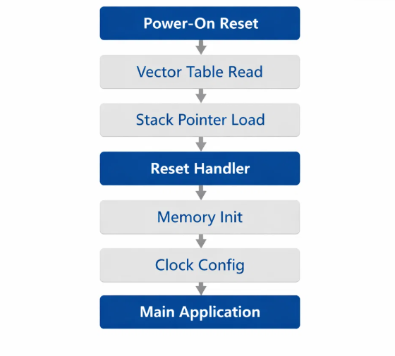
Ever wondered what happens in those crucial milliseconds between powering on a smart device and seeing it spring to life? The journey from a cold hardware reset to a running application is one of the most fundamental processes in embedded systems, yet it stays invisible to almost everyone who isn't the engineer who wrote it.
Unlike desktop computers with complex BIOS systems, microcontrollers follow an elegant and deterministic boot sequence. This post walks through that complete process using real examples from an STM32H5-based system, showing how hardware and software work together to produce reliable startup behavior.
The hardware reset: where it all begins
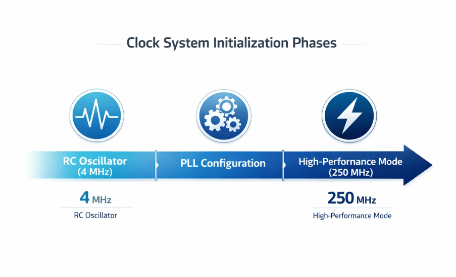
When power is first applied, three critical hardware events happen in rapid succession. First, the power supply stabilizes, triggering internal voltage detectors, the STM32H5 series has multiple power domains that all need to reach stable levels before any code executes. Next, the internal RC oscillator starts, providing a basic clock source, running conservatively at 4MHz during this phase for reliable operation across temperature and voltage variation. Finally, once stable, the Cortex-M33 core performs its first memory access, reading the reset vector from flash memory at address 0x08000000. That single address contains everything the processor needs to begin executing code.
The vector table: the system's address book
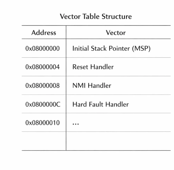
The vector table is the microcontroller's directory of critical addresses, sitting at the very start of flash and holding pointers to exception handlers and the initial stack pointer:
/* From startup_stm32h562xx.s */
g_pfnVectors:
  .word  _estack                    /* Initial Stack Pointer */
  .word  Reset_Handler             /* Reset Handler */
  .word  NMI_Handler               /* Non-Maskable Interrupt */
  .word  HardFault_Handler         /* Hard Fault Handler */
The first two entries are critical. The stack pointer (MSP) points to the top of the main stack in RAM, and the reset handler address identifies the first function to execute. This design means that even before any initialization code runs, the processor already knows exactly where its stack lives and which function to call first.
Memory layout: the foundation
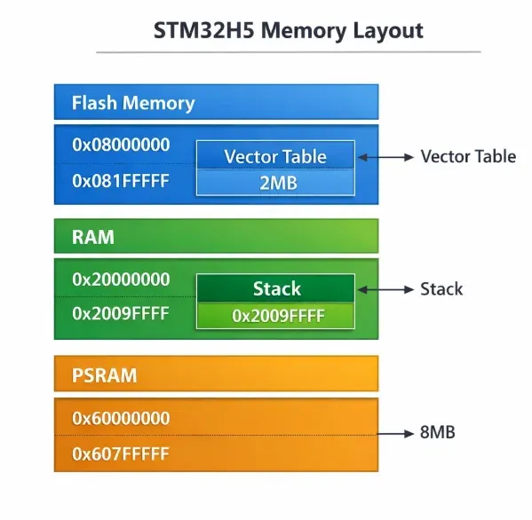
The linker script defines the memory architecture that makes boot possible:
MEMORY
{
  RAM    (xrw) : ORIGIN = 0x20000000, LENGTH = 640K
  FLASH  (rx)  : ORIGIN = 0x8000000,  LENGTH = 2048K
  PSRAM  (xrw) : ORIGIN = 0x60000000, LENGTH = 8M
}
Flash holds read-only code and constants, including the vector table. RAM stores runtime data, stack, and heap. PSRAM provides extended memory for large data buffers, critical for imaging applications like camera frame storage. The linker script uses a KEEP directive to make sure the vector table always occupies the first bytes of flash where the hardware expects it, preventing optimization from accidentally removing this critical structure.
The reset handler: system initialization
The reset handler, written in assembly, performs low-level initialization that can't happen in C, following a precise sequence. Stack pointer setup loads the main stack pointer from the vector table's first entry, establishing the foundation for all function calls. Data initialization copies initialized variables from flash to RAM, since a global like int counter = 42; exists as a constant in flash and has to be copied to RAM where it can actually be modified. BSS clearing zeros out uninitialized global variables, so anything declared without an initializer starts predictably at zero, not garbage. Clock configuration transitions from the conservative 4MHz RC oscillator to high-performance external crystals through PLL configuration, reaching the target operating frequency. C runtime setup prepares the environment for C code execution, including the heap and standard library support.
Multi-stage boot architecture
Real embedded systems implement multi-stage boot beyond basic hardware init. Stage 1 validates hardware functionality, external PSRAM, OCTOSPI flash communication, and bus transceivers. Stage 2 mounts the filesystem, initializing storage and validating integrity. Stage 3 starts application services, sensor interfaces and communication protocols. This layered approach allows graceful degradation, if filesystem mounting fails, the device can still operate with reduced functionality while logging diagnostics for troubleshooting.
Error handling and recovery
Modern embedded systems build in sophisticated error handling during boot. Flash corruption detection validates critical code sections with checksums, enabling automatic recovery from backup regions. Clock failure triggers an automatic fallback to the internal RC oscillator, allowing safe-mode operation for diagnostic access. Memory test procedures verify PSRAM functionality through pattern testing, and stack overflow detection plus heap integrity checks prevent silent failures that could otherwise surface much later during operation.
Performance optimization strategies
Critical applications need fast boot times. Parallel initialization tackles multiple peripherals simultaneously, using DMA for memory operations during setup and overlapping filesystem mounting with hardware tests. Selective feature enabling only initializes required peripherals, deferring non-critical setup until after the main application starts. Cache pre-loading fetches frequently used code into instruction cache before it's needed. Strategic memory placement matters too, boot code lives in the fastest flash regions, interrupt vectors align for optimal access, and the stack occupies the fastest RAM to minimize latency during critical operations.
Real-world challenges
Temperature variation creates real challenges: cold starts extend RC oscillator stabilization time and increase flash access delays, while voltage fluctuation needs brown-out detection during boot and graceful restart mechanisms on power interruption. Manufacturing testing validates boot sequence timing to catch defects affecting startup reliability, and debug interfaces like JTAG/SWD have to stay accessible during boot, with recovery mode entry mechanisms for field diagnostics.
Debugging the boot process
Common failures have recognizable signatures. Vector table corruption causes immediate hard faults or infinite reset loops, verify flash programming and protect critical regions. Stack overflow during initialization manifests as erratic behavior, monitor stack usage with a debugger and increase allocation if needed. Clock configuration errors produce incorrect timing and peripheral malfunctions, which need verification of PLL settings and external crystal connectivity, with validation logic and fallback modes to keep operating when primary clock sources fail.
Why it matters at Hoomanely
Our pet health monitoring devices have to boot consistently and predictably every single time, whether it's a sensor array monitoring vital signs or a camera system capturing behavioral patterns. Reliable boot sequences make sure we never miss critical health indicators, and that deterministic behavior is the foundation of trustworthy pet healthcare technology. Optimized boot enables quick recovery when devices restart, minimizing gaps in monitoring, since for continuous observation tracking temperature, activity, or respiratory patterns, every second of downtime is lost health data. Built-in boot-time diagnostics also support remote monitoring across our device fleet, letting us catch boot issues proactively before devices fail completely.
Key takeaways
The boot process is elegant cooperation between hardware features (vector tables, memory controllers) and software design (linker scripts, initialization code) to create reliable startup. Unlike complex operating systems, microcontroller boot sequences follow predictable, repeatable patterns that enable real-time guarantees, essential for medical-grade monitoring devices. The same fundamental boot concepts scale from a simple temperature sensor to a complex imaging system. And modern boot sequences build in comprehensive error detection and recovery, keeping systems reliable even under temperature extremes or power fluctuation.



