When 10 Kilometers Became 500 Meters: My LoRa Wake-Up Call
Last year at Hoomanely Inc., we were developing an IoT sensor that needed to communicate across our campus. On paper, LoRa promised 10km range. Our prototype? Barely reached the parking lot.
The antenna looked fine. The code was solid. The radio chip was premium quality. So what went wrong?
Turns out, I'd placed a simple LED driver circuit just 8 millimeters from the antenna trace. Less than the width of your thumbnail. That tiny mistake cut our range by 95%.
That day taught me something crucial: with RF design, invisible rules matter more than visible components.
What Makes LoRa Special (and Tricky)?
Let me explain LoRa without the jargon. Think about how you communicate in a noisy room:
WiFi/Bluetooth approach: Shout really loud, but only people nearby hear you clearly.
LoRa's approach: Whisper very slowly and carefully, so even someone across the building can understand every word.
LoRa trades speed for distance. It sends data slowly, using clever tricks to make weak signals readable even after traveling kilometers. This is why a sensor in a remote field can talk to a gateway on a city rooftop without any cellular network or WiFi infrastructure.
The catch? It's incredibly sensitive to interference. And when you're building a real product, your LoRa radio isn't alone on the circuit board.
The Reality of Shared Boards
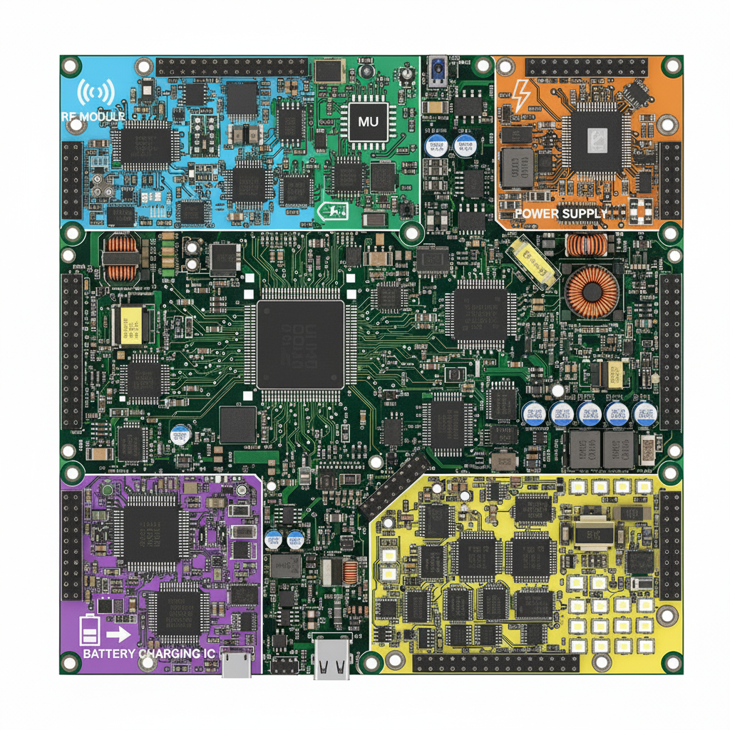
Here's what nobody tells you in textbooks. A real IoT device isn't just a radio module. It's:
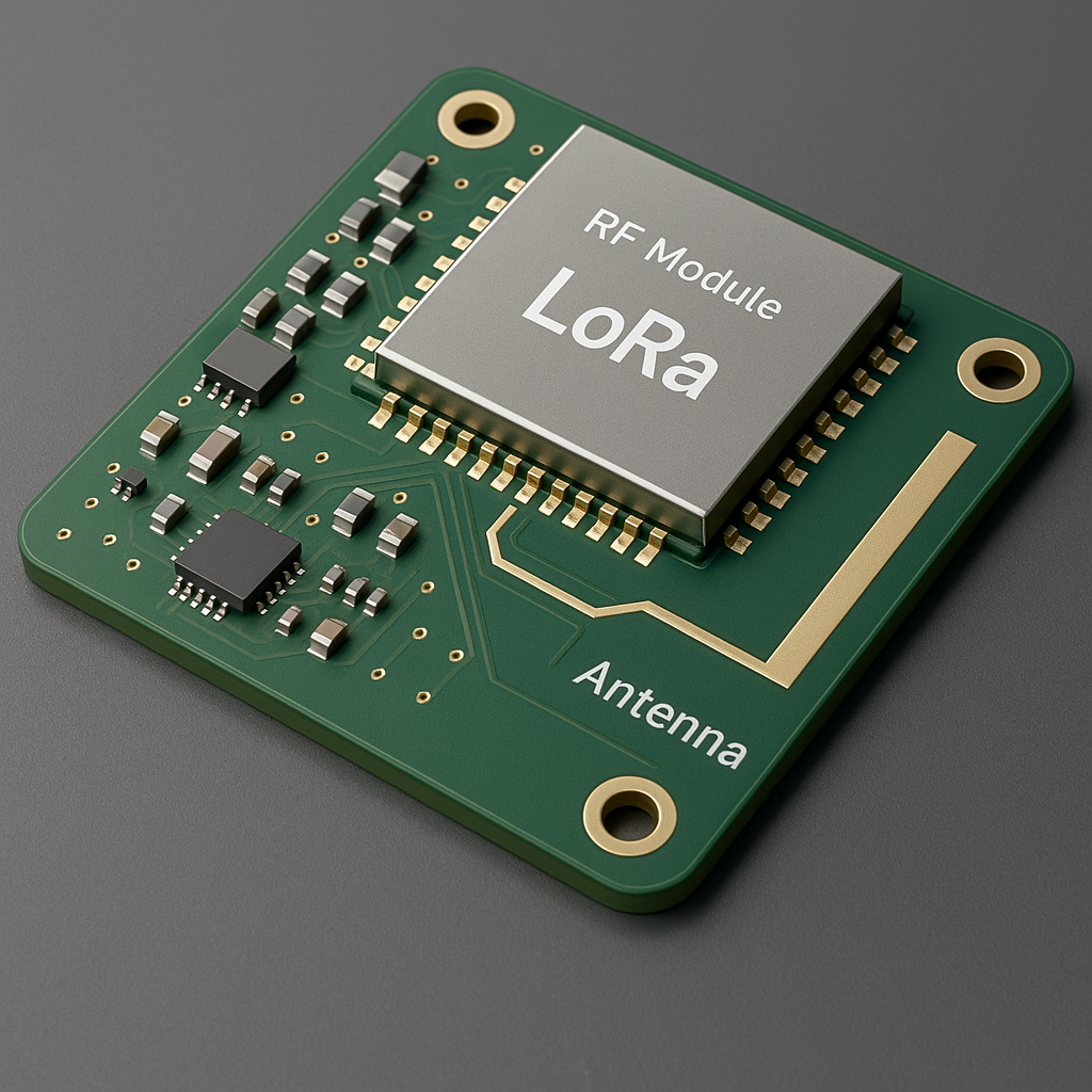
- A LoRa radio that needs absolute silence
- A microcontroller running at 48MHz
- Sensors collecting data
- A switching power supply creating electrical noise
- LEDs blinking
- Maybe GPS, maybe Bluetooth
- Battery charging circuits
All of this packed onto one small PCB, with every circuit fighting for space. It's like trying to record a podcast in a construction zone. Every component is a potential source of interference.
The Three Rules I Wish I'd Known Earlier
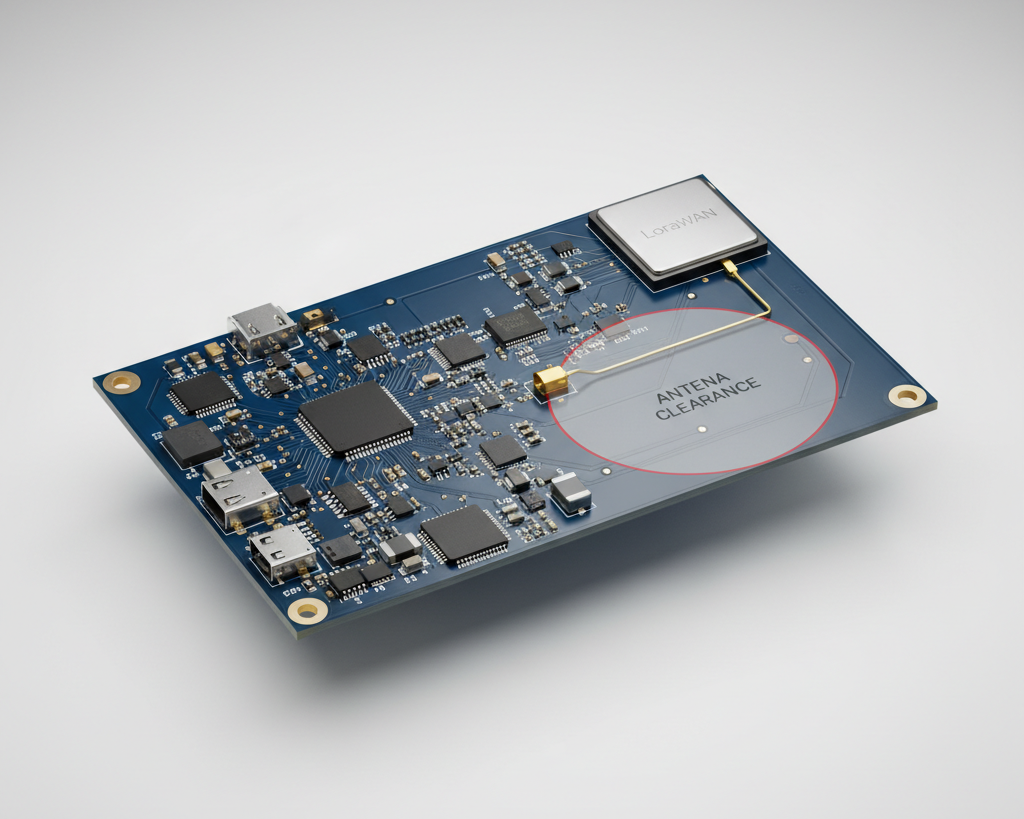
Rule #1: Respect the Antenna's Personal Space
At Hoomanely, we learned this the hard way. Antennas need a keep-out zone, and it's non-negotiable.
Think of your antenna like a really sensitive microphone that also happens to be a speaker. You wouldn't press your hand against a microphone while recording, right? Same principle here.
What stays out of the keep-out zone:
No copper ground plane directly under the antenna (minimum 6-8mm clearance). Ground planes reflect and distort the RF field, like acoustic panels changing how sound bounces in a room.
No signal traces nearby. They couple RF energy and create interference paths.
No components within 10mm of where the antenna connects. Even a tiny capacitor can detune everything.
No metal objects behind the antenna. Batteries, mounting screws, shielding cans—they all affect antenna performance.
Here's a story from one of our projects. We had beautiful antenna measurements in the lab. The antenna vendor's application note said "5mm keep-out." We used 5mm exactly. Field testing was disappointing.
After three frustrating days, we extended the keep-out to 10mm by removing a small copper pour we thought was "far enough away." Range improved by 3.5x. Same hardware, same antenna, just proper spacing.
The lesson? Antenna datasheets give minimums. If you want maximum performance, give generous margins.
Rule #2: Budget Your Noise Like You Budget Your Power
This concept sounds technical but it's actually pretty simple. Every circuit on your board generates electrical noise. Your LoRa radio is trying to detect incredibly weak signals, sometimes as faint as 0.00000000000002 watts.
If your board is generating noise in the same frequency range, you're essentially trying to hear a whisper in a nightclub.
The biggest noise culprits we deal with:
Switching power supplies are enemy number one. They turn on and off thousands of times per second, creating interference across a wide range of frequencies. Super efficient for battery life, terrible for RF.
High-speed digital circuits, especially anything above 20MHz. Clock signals create harmonics that can land right in your LoRa operating band.
LED circuits and motor drivers. Any rapid switching creates noise.
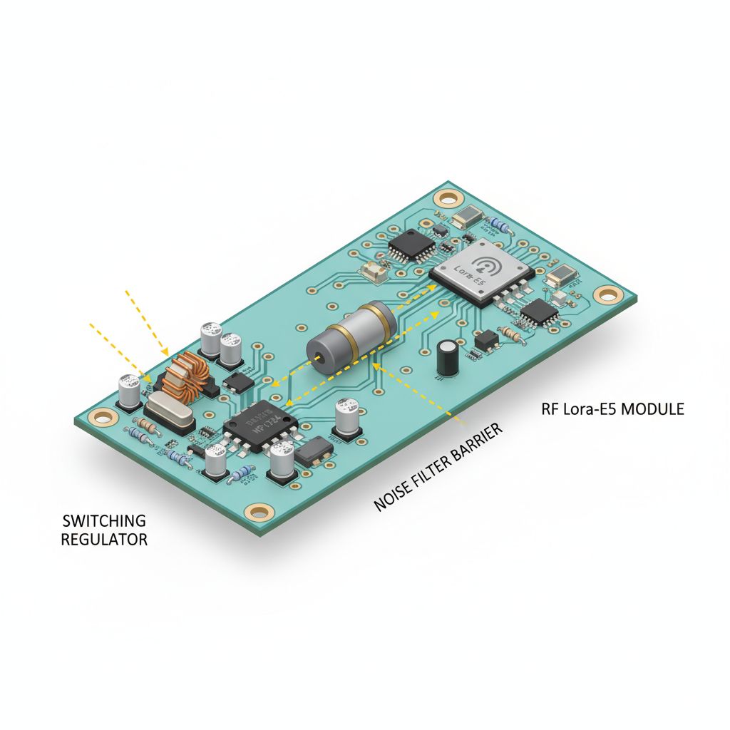
At Hoomanely, we've developed a few strategies:
We give the LoRa module its own clean power supply with heavy filtering. Sometimes that means using a less-efficient linear regulator just for the radio section, accepting the small efficiency hit for much better range.
We physically separate the noisy stuff. Keep your DC-DC converters and high-speed digital circuits at least 20mm away from the RF section. More if you can afford the board space.
We use ferrite beads on power lines feeding sensitive RF circuits. Think of them as noise filters that block high-frequency garbage while letting clean DC power through.
One trick that's helped us: when choosing your microcontroller's clock frequency, avoid ones that create harmonics near your LoRa frequency. For 915MHz LoRa, a 32MHz crystal creates harmonics at 896MHz and 928MHz—right in your operating band. A 40MHz crystal? Much cleaner harmonic spacing.
Rule #3: The Ground Plane Under RF Traces is Sacred
This is where things get a bit counterintuitive. At RF frequencies, electrical current doesn't just flow through the signal trace. It also flows back through the ground plane directly underneath.
If you break that ground plane, you've broken the RF signal path. The signal can't find its way home. It starts radiating everywhere, coupling into other traces, and generally causing chaos.
Our RF layout rules at Hoomanely:
The RF section gets its own dedicated, completely unbroken ground plane. No exceptions, no compromises.
RF traces are as short as physically possible. At 915MHz, a few millimeters actually matter.
We surround the RF section with ground stitching vias every 5mm, creating what's basically an electromagnetic fence.
No other traces cross under or over RF traces if we can avoid it. And definitely not at perpendicular angles.
The antenna feed line gets special treatment. It needs to be exactly 50 ohms impedance, which means specific trace width based on your PCB stackup. Most PCB vendors have calculators for this. Use them.
The Power Supply Problem Nobody Talks About
In our early designs at Hoomanely, we used a single switching regulator to power everything. Battery efficiency was great. RF performance was average.
The issue? Switching regulators are electrically noisy by design. Those fast switching edges create interference that couples directly into your sensitive RF circuits.
We now use a two-tier approach. The main switching regulator powers the microcontroller, sensors, and peripherals—everything that doesn't care about electrical noise. Then we use either a separate linear regulator or heavy LC filtering to create ultra-clean power just for the LoRa module.
In one product, this change alone improved our receive sensitivity by 14dB. In practical terms, that's roughly 3-4x better range. Same radio chip, just cleaner power.
Is it less efficient? Slightly. Is it worth it? Absolutely.
What Good Layout Looks Like
After several iterations, here's our current approach:
The LoRa module and antenna live in one corner of the board. The rest of the board is organized to keep noise sources as far away as possible. Power supply at the opposite corner. High-speed digital circuits nowhere near the RF section.
Solid, continuous ground plane under the entire RF area. Ground stitching vias everywhere around the perimeter. Wide, clear keep-out zones around the antenna.
The antenna feed trace is short, 50 ohms impedance, with smooth curves instead of sharp 90-degree turns. Ground plane solid underneath, no breaks, no interruptions.
Separate power domains with filtering between them. The LoRa module sees clean, quiet power even when the rest of the board is switching loads on and off.
The Results
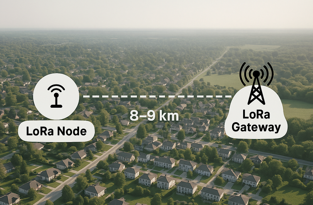
Following these principles, our latest sensor design achieves 8-9km line-of-sight range in suburban environments. That's pretty close to the theoretical maximum for the LoRa settings we're using.
More importantly, performance is consistent and predictable. We're not chasing mysterious range problems in field testing anymore.
A Few Closing Thoughts
RF layout isn't magic, but it does require respecting rules you can't see. Electromagnetic fields don't care about your PCB routing convenience or your tight space constraints.
The invisible keep-out zones, the clean ground planes, the careful power supply design—these aren't optional optimizations. They're the difference between a product that barely works and one that actually delivers on LoRa's promise.
My advice? Give RF the respect and space it demands. Your future self, dealing with field testing instead of re-spins, will thank you.