A Frame Without a CPU: An All-Hardware Image Pipeline
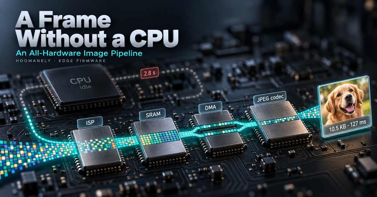
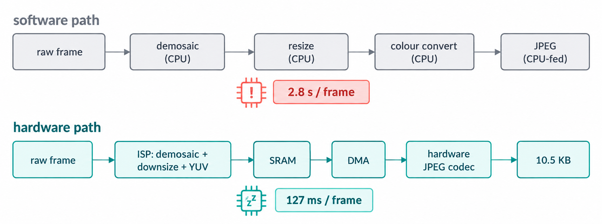
A camera module's job sounds simple: take a picture of the pet, shrink it, compress it, save it. On a microcontroller-class part, the naive version of that pipeline eats the processor. Converting a raw sensor frame into colour is millions of multiply-adds; resizing it is millions more; JPEG-compressing the result is heavier still. On our new camera module that software path cost about 2.8 seconds per frame — with the core doing nothing else.
The same frame now takes 127 milliseconds, and the processor barely participates. Every stage — colour reconstruction, downscaling, colour-space conversion, compression, and the transfer into the codec — runs on a dedicated hardware block, chained together so the image flows from sensor to finished JPEG with the CPU only steering. This post is about how that pipeline was built, stage by stage, and what it took to make each block hand off cleanly to the next.
The Problem: Pixels Are Expensive on a Core
A sensor frame arrives as raw Bayer data — one colour sample per pixel, ten bits each, in a mosaic pattern. Nothing downstream can use it directly. It has to be demosaiced into full colour, scaled to a useful size, converted to the luma/chroma layout a JPEG codec expects, and then compressed.
Done in software, every one of those steps touches every pixel at least once. At 1536×864 that is over 1.3 million pixels per stage, on a core that also has to run capture, storage, the bus, and — eventually — on-device AI. The first working software path measured 2.5 seconds just for demosaic and colour conversion.
The chip, though, contains a dedicated image signal processor, a hardware JPEG codec, and a high-performance DMA engine. The engineering task was to make the frame travel through all three without the CPU ever holding the pixels.
The Approach: Chain the Blocks, Move Nothing Twice
The design has three rules. First, every pixel-touching operation goes to hardware — the ISP handles demosaic, downscaling and colour conversion in a single pass. Second, data lands once, in the layout the next block wants — the ISP writes its output in the exact luma/chroma planar arrangement the codec consumes, so no reformatting pass is needed. Third, the transfer into the codec is DMA-driven, so the processor is not the bottleneck between memory and compression.
What the CPU still does is small and deliberate: it configures each block, assembles compact input windows one step ahead of the codec, and copies the compressed output chunks to their destination. Everything else is hardware.
The Process: Four Stages That Hand Off Cleanly
Stage 1 — Demosaic and downsize in the ISP
The ISP pipe is configured to reconstruct colour from the sensor's mosaic pattern and to scale the frame down in the same pass. Both are a handful of register-level configuration calls; the pixels never visit the CPU:
379	    DCMIPP_RawBayer2RGBConfTypeDef dm = {
380	        .RawBayerType  = DCMIPP_RAWBAYER_RGGB,
381	        .VLineStrength = 0, .HLineStrength = 0, .PeakStrength = 0, .EdgeStrength = 0,
382	    };
383	    if (HAL_DCMIPP_PIPE_SetISPRawBayer2RGBConfig(&hdcmipp, DCMIPP_PIPE1, &dm) != HAL_OK) return -5;
384	    if (HAL_DCMIPP_PIPE_EnableISPRawBayer2RGB(&hdcmipp, DCMIPP_PIPE1) != HAL_OK) return -5;
The downscaler takes fixed-point ratios — the comment records the scaling convention so nobody has to rediscover it:
386	    /* Downsize: ratio in u3.13 (8192 = 1.0), div factor = 1024*dst/src */
387	    DCMIPP_DownsizeTypeDef ds = {
388	        .HSize      = APP_CAM_PIPE1_W,
389	        .VSize      = APP_CAM_PIPE1_H,
390	        .HRatio     = (APP_CAM_WIDTH  * 8192u) / APP_CAM_PIPE1_W,
391	        .VRatio     = (APP_CAM_HEIGHT * 8192u) / APP_CAM_PIPE1_H,
392	        .HDivFactor = (1024u * APP_CAM_PIPE1_W) / APP_CAM_WIDTH,
393	        .VDivFactor = (1024u * APP_CAM_PIPE1_H) / APP_CAM_HEIGHT,
394	    };
395	    if (HAL_DCMIPP_PIPE_SetDownsizeConfig(&hdcmipp, DCMIPP_PIPE1, &ds) != HAL_OK) return -6;
Output: a clean 768×432 frame, produced with zero milliseconds of CPU time.
Stage 2 — Land it in the codec's native layout
Rather than emit RGB and convert later, the ISP's packer is set to write semi-planar 4:2:0 — a full-resolution luma plane followed by an interleaved chroma plane — which is what a JPEG encoder wants. The colour-space conversion happens in the packer itself.
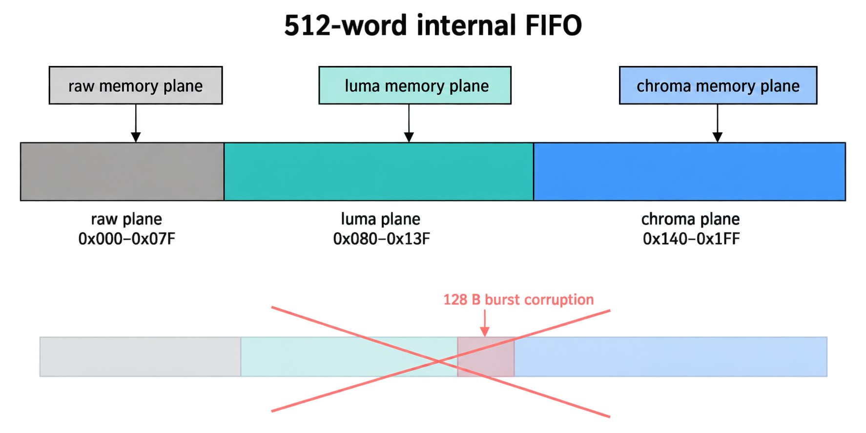
Writing two planes concurrently exposed the subtlest part of the whole pipeline. The ISP's memory interface allocates a small internal FIFO per memory plane, and the planes must not share FIFO space:
299	    /* Build U (2026-09-25): the IPPLUG clients are per MEMORY PLANE, not per
300	     * pipe: client 1 = pipe0, client 2 = pipe1 plane 0 (Y), client 3 = pipe1
301	     * plane 1 (UV), client 4 = pipe1 plane 2, client 5 = pipe2. Build N's
302	     * client-2 range 0x100-0x1FF overlapped client 3 (reset 0x140-0x18F) and
303	     * corrupted the chroma plane in 128 B bursts. Non-overlapping split of the
304	     * 512-word FIFO for the three clients we use: c1 0x000-0x07F (reset),
305	     * c2 0x080-0x13F (reset, 192 words: fine for 768 B Y lines), c3 0x140-0x1FF. */
306	    plug.DPREGStart = 0x080;
307	    plug.DPREGEnd   = 0x13F;
308	    if (HAL_DCMIPP_SetIPPlugConfig(&hdcmipp, &plug) != HAL_OK) return -7;
309	    plug.Client     = DCMIPP_CLIENT3;
310	    plug.DPREGStart = 0x140;
311	    plug.DPREGEnd   = 0x1FF;
A 512-word FIFO, carved into three non-overlapping windows sized to the line lengths each plane actually produces. Get this right and the chroma plane is pristine; get it wrong and colour corrupts in 128-byte bursts while every status register reports success.
Stage 3 — Feed the codec in stripes, not frames
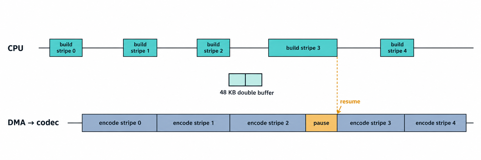
A hardware JPEG codec consumes the image in minimum coded units — 16×16 blocks arranged in a specific order. Building the whole frame in that order would need a full extra frame buffer. Instead, the code assembles one 16-row stripe at a time into a small 48 KB double buffer in fast internal RAM, and hands each stripe to the codec as it's ready:
41	#define STRIPE_MAX_MCU   64U                                  /* up to 1024 px wide */
42	static uint8_t s_stripe[2][STRIPE_MAX_MCU * 384U] __attribute__((aligned(32)));   /* 48 KB, internal RAM (fast) */
43
44	/* one 16-row stripe of 4:2:0 MCUs: Y0 Y1 Y2 Y3 Cb Cr, 64 B each, 8-byte rows */
45	static uint32_t build_stripe(uint32_t k, uint8_t *dst)
46	{
47	    uint32_t t0 = HAL_GetTick();
48	    const uint32_t w = s_enc.w, cw = w / 2U, row0 = k * 16U;
49	    for (uint32_t mx = 0; mx < w / 16U; mx++) {
50	        uint8_t *m = dst + mx * 384U;
51	        for (uint32_t b = 0; b < 4U; b++) {
52	            const uint8_t *src = s_enc.py + (row0 + (b >> 1) * 8U) * w + mx * 16U + (b & 1U) * 8U;
53	            uint8_t *d = m + b * 64U;
54	            for (uint32_t r = 0; r < 8U; r++) { memcpy(d + r * 8U, src + r * w, 8U); }
55	        }
Because the ISP already delivered chroma interleaved, the stripe builder de-interleaves it with a tight inner loop — the only per-pixel work the CPU does, and it is a byte shuffle, not arithmetic:
63	        } else {                                      /* semi-planar: U,V interleaved, pitch w */
64	            const uint8_t *suv = s_enc.pu + (row0 / 2U) * w + mx * 16U;
65	            for (uint32_t r = 0; r < 8U; r++) {
66	                const uint8_t *q = suv + r * w; uint8_t *du = m + 256U + r * 8U, *dv = m + 320U + r * 8U;
67	                for (uint32_t c = 0; c < 8U; c++) { du[c] = q[2U * c]; dv[c] = q[2U * c + 1U]; }
68	            }
69	        }
No frame-sized MCU buffer, no colour maths — 768×432 at quality 85 compresses to 10.5 KB.
Stage 4 — Let DMA carry it
The final step removed the last bottleneck: the CPU polling the codec's FIFOs. Two DMA channels now feed the codec's input and drain its output, interrupt-driven. The CPU's job shrinks to building the next stripe while the DMA moves the current one — a classic producer/consumer with a two-slot buffer.
The interesting part is what happens when the CPU falls behind. The codec's data-request callback checks whether the next stripe is built yet; if it isn't, it pauses the codec's input rather than feeding stale data:
160	void HAL_JPEG_GetDataCallback(JPEG_HandleTypeDef *h, uint32_t NbEncodedData)
161	{
162	    (void)NbEncodedData;
163	    if (s_enc.planar && s_enc.dma) {
164	        s_enc.consumed++;
165	        uint32_t next = s_enc.consumed;
166	        if (next >= s_enc.stripes) { HAL_JPEG_ConfigInputBuffer(h, s_stripe[0], 0U); return; }   /* all fed */
167	        if (s_enc.built > next) { HAL_JPEG_ConfigInputBuffer(h, s_stripe[next & 1U], (s_enc.w / 16U) * 384U); }
168	        else { s_enc.waiting = 1; HAL_JPEG_Pause(h, JPEG_PAUSE_RESUME_INPUT); }
169	        return;
170	    }
And the main loop resumes it the moment a stripe lands, with the hand-off guarded against the interrupt racing it:
468	    while (!s_enc.done) {
469	        if (s_enc.built < s_enc.stripes && (s_enc.built - s_enc.consumed) < 2U) {
470	            uint32_t k = s_enc.built;
471	            (void)build_stripe(k, s_stripe[k & 1U]);
472	            __disable_irq();
473	            s_enc.built = k + 1U;
474	            if (s_enc.waiting && s_enc.built > s_enc.consumed) {
475	                s_enc.waiting = 0;
476	                HAL_JPEG_ConfigInputBuffer(&hjpeg, s_stripe[s_enc.consumed & 1U], n);
477	                __enable_irq();
478	                HAL_JPEG_Resume(&hjpeg, JPEG_PAUSE_RESUME_INPUT);
479	            } else { __enable_irq(); }
480	        }
The result was validated the only way that counts: the same frame encoded three times by DMA and once by polling, and the DMA output was byte-identical.
The Results
The end-to-end numbers tell the story. Demosaic and colour conversion: 2.5 s → 0 ms on the CPU. Full encode of a 768×432 frame at quality 85: 455 ms polling → 127 ms with DMA, the remaining time being stripe assembly. Output size: 10.5 KB. Every stage verified on hardware the same afternoon, with a saved evidence frame — clean, correctly coloured, no artefacts.
The storage side kept pace: the module's eMMC path was moved to DMA and high-speed mode in the same session, reaching 28.8 MB/s write and 43.6 MB/s read, so a compressed frame lands on disk in well under a millisecond. A pet's picture now goes from photons to a stored JPEG with the processor almost entirely free.
Why It Matters at Hoomanely
Hoomanely is reinventing healthcare for pets — replacing reactive, imprecise care with continuous, clinical-grade monitoring that catches problems early. Our devices form a Physical Intelligence ecosystem: sensors fused at the edge, feeding the Biosense AI Engine that turns raw signals into personalized, preventive insights.
This pipeline is the imaging foundation of our next-generation sensor module. Freeing the processor from pixel-pushing is not an optimisation for its own sake — it is what makes room for on-device inference. A camera module that spends its cycles compressing frames cannot also run the models that read them; one that offloads the whole capture path to hardware can.
It also embodies how we like to build: measure the software path honestly, move each stage to the silicon designed for it, verify every hand-off against the previous result, and keep the numbers.
Key Takeaways
- Put every pixel-touching stage in hardware. Demosaic, downscale and colour conversion belong in the ISP; the CPU should configure, not compute.
- Land data once, in the next block's native layout. Writing semi-planar 4:2:0 straight from the ISP removed an entire reformatting pass.
- Budget shared FIFO space per plane, precisely. Overlapping windows corrupt silently; the split is part of the design, not a tuning detail.
- Feed codecs in stripes with a small double buffer. No frame-sized staging buffer, and the CPU stays one step ahead.
- Let DMA drive the codec, and pause rather than lie. When the producer falls behind, stop the consumer — then prove the DMA path byte-identical to the polled one.
Author's Note
This pipeline was brought up on the evaluation board for Hoomanely's next camera module, one stage at a time, each verified on hardware before the next was started. The numbers in this post are the ones printed on the console that afternoon. It is the kind of work that looks like nothing when it is finished — a frame appears, a JPEG is written, the CPU is idle — and that quietness is exactly the point.