Beyond the Datasheet: Achieving LoRa Max Performance Through Proactive RF System Integration
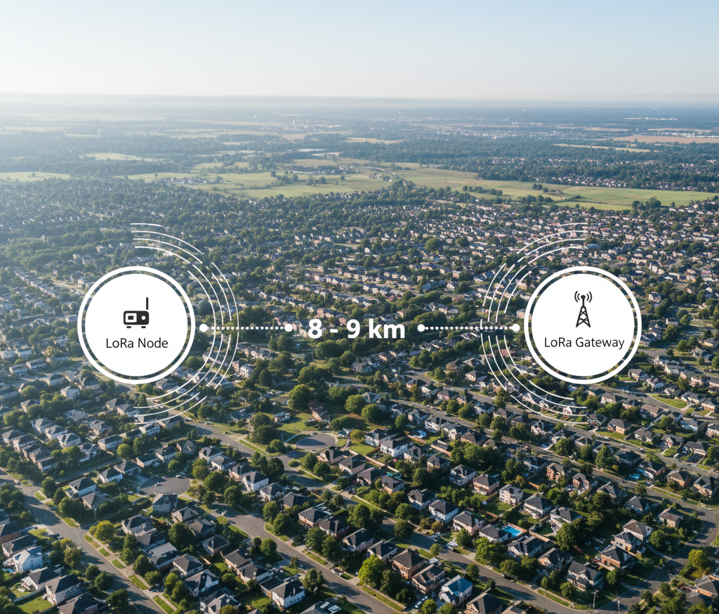
At Hoomanely Inc., we move beyond theoretical limits to ensure our connected products deliver predictable, robust performance in the field. Our goal for the IoT sensor network was to maximize the 10km potential of LoRa. By establishing and rigorously enforcing three core RF design principles from the initial PCB layout, we consistently achieved reliable, line-of-sight range between 0.5 and 1 kilometres in demanding suburban environments.
This success is rooted in treating the LoRa radio as part of a finely tuned electromagnetic system, actively mitigating noise and optimizing antenna mechanics during the PCB design phase.
What Makes LoRa Special (and Tricky)?
Let me explain LoRa without the jargon. Think about how you communicate in a noisy room:
WiFi/Bluetooth approach: Shout really loud, but only people nearby hear you clearly.
LoRa's approach: Whisper very slowly and carefully, so even someone across the building can understand every word.
LoRa trades speed for distance. It sends data slowly, using clever tricks to make weak signals readable even after traveling kilometers. This is why a sensor in a remote field can talk to a gateway on a city rooftop without any cellular network or WiFi infrastructure.
The catch? It's incredibly sensitive to interference. And when you're building a real product, your LoRa radio isn't alone on the circuit board.
The Reality of Shared Boards
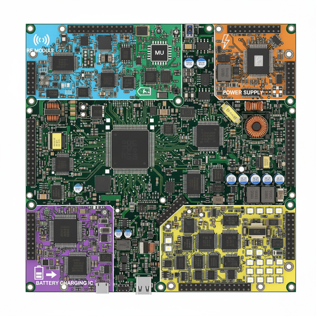
Here's what nobody tells you in textbooks. A real IoT device isn't just a radio module. It's:
- A LoRa radio that needs absolute silence
- A microcontroller running at 48MHz
- Sensors collecting data
- A switching power supply creating electrical noise
- LEDs blinking
- Maybe GPS, maybe Bluetooth
- Battery charging circuits
All of this packed onto one small PCB, with every circuit fighting for space. It's like trying to record a podcast in a construction zone. Every component is a potential source of interference.
Achieving Predictable Long-Range LoRa Communication
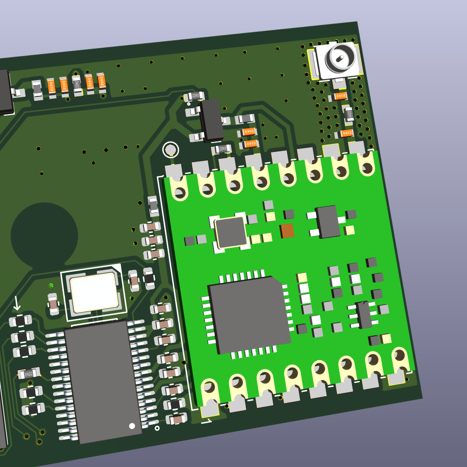
Rule #1: The Non-Negotiable Antenna Keep-Out Zone
Antenna efficiency is the primary factor driving LoRa range. Experience shows that relying on minimum datasheet recommendations is a risk to production reliability. Therefore, we established an internal, stricter protocol for antenna placement to guarantee the radiating field remains unobstructed and undistorted.
Hoomanely RF Layout Standards:
- Generous Physical Clearance: We mandate a minimum 10-millimeter, component and trace-free keep-out zone around the antenna’s feed and radiating element. This standard minimizes electromagnetic coupling and ensures stable signal integrity across all production batches.
- Ground Plane Isolation: A continuous copper ground plane is intentionally removed from the critical area (typically 6-8mm clearance) immediately beneath the antenna. This prevents the ground plane from acting as a reflector that would detune the antenna, preserving the intended radiation pattern.
Strict Component Discipline: No circuit element—not even minor decoupling capacitors or test points—is permitted within the critical 10mm radius. This discipline is essential for maintaining the antenna's intended impedance match and maximizing its radiating efficiency.
Rule #2: Dedicated, Low-Noise Power Delivery Architecture
LoRa modules require extreme electrical silence to detect signals measured in femtowatts (less than 10^-14 Watts). Our approach is to treat electrical noise as a resource to be managed, allocating only the cleanest power to the radio subsystem.
Proactive Power Management Strategies:
- Strategic Two-Tier Power Architecture: We employ a dedicated power system to isolate the sensitive RF components.
- The main, high-efficiency switching regulator powers noise-tolerant digital circuits and peripherals (MCU, sensors).
- A separate linear regulator (LDO) or a heavy LC filtering stage is exclusively used to supply ultra-clean DC power to the LoRa module. While this is a planned trade-off on overall efficiency, the resulting 3-4x range improvement (validated by up to 14dB better receiver sensitivity) is a critical performance imperative.
- Physical Segregation: High-speed digital circuits and noise generators, particularly switching power supplies, are placed a minimum of 20mm away from the RF section to prevent near-field electromagnetic interference.
- Broadband Noise Filtering: Ferrite beads are standard on all power lines feeding the RF circuitry. These act as passive high-frequency chokes, blocking noise before it can modulate the sensitive radio circuits.
Harmonic Avoidance: We perform spectral analysis on our chosen microcontroller clock frequencies to ensure that system clock harmonics do not align with the target LoRa operating band (e.g., 915MHz).
Rule #3: Maintaining Ground Plane Integrity in the RF Section
At RF frequencies, the ground plane is the critical return path. Any break creates a path discontinuity, resulting in unpredictable signal reflection and unintended radiation. Our layout adheres to a strict commitment to ground plane integrity to manage signal return loss.
Signal Integrity and EMI Containment:
- Unbroken Dedicated Ground Plane: The RF section must sit over a continuous, uninterrupted ground plane. This establishes a stable reference and minimizes return current loop inductance.
- 50-Ohm Impedance Matching: The antenna feed line is precisely designed to a 50-ohm characteristic impedance, calculated based on the PCB stack-up and trace width. This critical step ensures maximum power transfer to the antenna and minimizes harmful signal reflection.
- RF Trace Management: RF traces are kept as short as feasible, utilize smooth curves instead of sharp 90-degree turns, and maintain a solid ground reference directly underneath across their entire length.
- Electromagnetic Fencing (Ground Stitching): High-density ground stitching vias are placed every 5mm around the perimeter of the RF section. This technique creates a low-impedance barrier, effectively isolating the RF domain and improving EMI containment.
By embedding these proven engineering principles into our initial hardware specifications, Hoomanely Inc. consistently delivers high-performance LoRa solutions that achieve near-theoretical range and predictable reliability, minimizing design iterations and accelerating time-to-market.
Conclusion: Integrated Design Blueprint and Performance Consistency
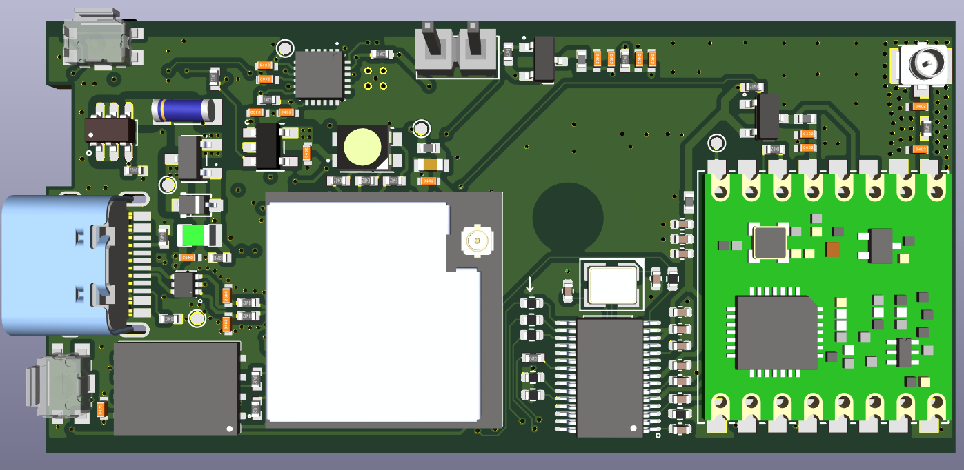
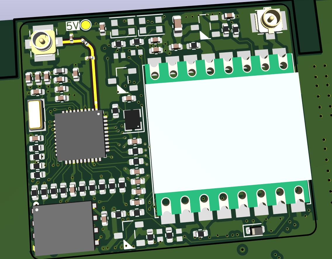
Following the robust Hoomanely layout standards ensures a reliable system blueprint:
- The LoRa module and antenna are positioned in one corner, with noise sources (power supply, high-speed digital) placed at the opposite end of the board.
- The entire RF area is isolated by a solid, continuous ground plane and shielded with perimeter ground stitching vias.
- The antenna feed trace is short, 50-ohm matched, and maintains ground integrity underneath.
The result of this disciplined approach is consistent, predictable range performance of 1km line-of-sight, which is near the theoretical maximum. By respecting the invisible rules of the electromagnetic field, we eliminate mysterious range problems and minimize costly design re-spins, ensuring our products deliver on LoRa's promise reliably in the field.


