
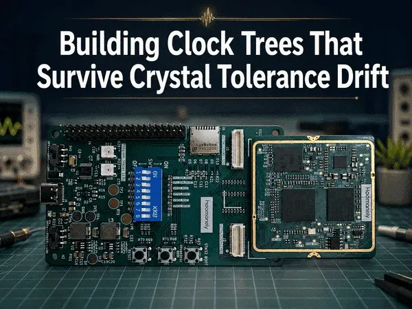
Building Clock Trees That Survive Crystal Tolerance Drift
Crystal tolerance budgeting, PLL lock monitoring, fallback oscillator paths, and clock-valid gating
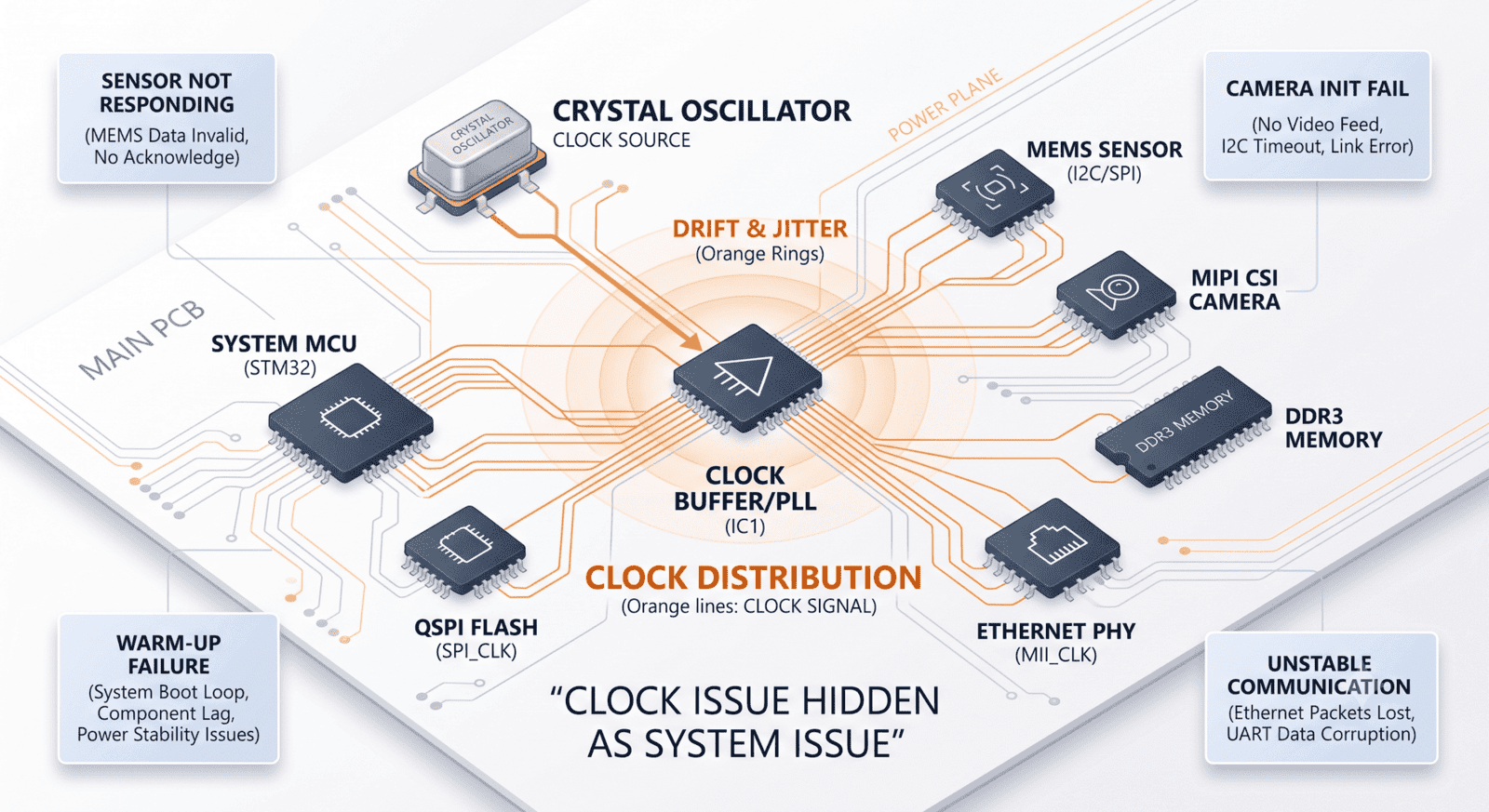
Clock failures rarely look like clock failures at first.
A sensor stops responding after a cold boot.
A camera interface works on one unit and fails on another.
A communication link becomes unstable only after the product warms up.
A processor boots correctly in the lab but behaves differently in the field.
A peripheral appears dead, even though power and reset look fine.
The schematic may show a crystal, a few load capacitors, an oscillator input, a PLL, and a clean-looking clock output. On paper, the timing source exists. In the real product, that is not enough.
A clock tree is not just a frequency generator.
It is the timing backbone of the system.
At Hoomanely, we do not treat clocks as background utilities. We treat them as shared infrastructure that must survive crystal tolerance, temperature drift, startup delay, PLL lock uncertainty, board variation, and subsystem dependency. A clock that works only under nominal bench conditions is not a product-grade clock.
The real question is not:
“Is there a crystal connected?”
The better question is:
“Can the entire system prove that its timing is valid before anyone depends on it?”
That is where clock-tree architecture begins.
Crystal Tolerance Is Not a Datasheet Footnote
Crystal tolerance often gets selected casually.
A designer chooses 8 MHz, 16 MHz, 24 MHz, 25 MHz, or 32.768 kHz. The crystal fits the footprint. The load capacitance looks familiar. The tolerance seems acceptable. The system boots.
But the crystal tolerance number is only one part of the real clock error.
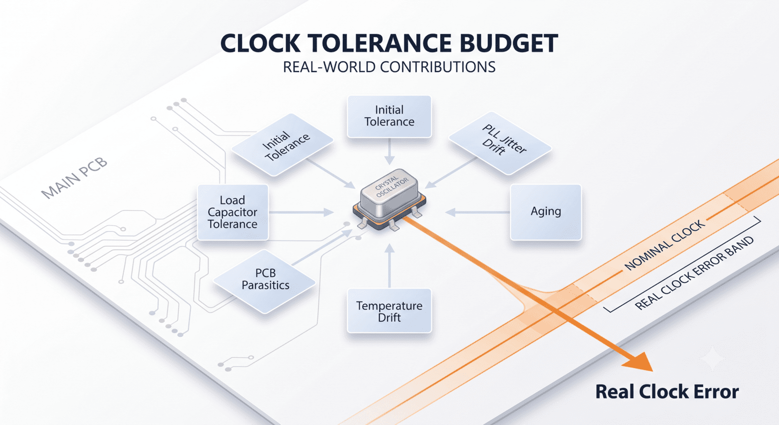
The actual frequency seen by the system depends on initial tolerance, load capacitance accuracy, PCB parasitics, temperature drift, aging, drive level, oscillator circuit behaviour, and sometimes even contamination or moisture in harsh environments.
A crystal marked ±20 ppm does not mean the full clock system is always ±20 ppm in the product.
The total budget may be wider.
For interfaces that tolerate broad timing error, this may not matter much. For systems involving USB timing, RF references, audio sampling, camera clocks, CAN bit timing, precision sensor sampling, timestamping, or long-term data accumulation, small errors can become visible.
The Hoomanely approach is to budget the clock like we budget power.
Not by assuming the nominal value, but by asking what the worst practical error can become across production and operating conditions.
A good clock budget includes:
- crystal initial tolerance,
- crystal temperature curve,
- aging over product life,
- load capacitor tolerance,
- PCB stray capacitance,
- oscillator input capacitance,
- PLL multiplication error or jitter,
- and peripheral tolerance limits.
This is not paperwork. It decides whether the clock is safe for the system it serves.
The Load Capacitor Choice Is Part of the Clock Tree
Many crystal problems begin around the two small capacitors beside the crystal.
They look simple, but they influence frequency accuracy and startup behavior. If the load capacitance is wrong, the oscillator may run slightly off-frequency. If the capacitors are too large, startup may slow down or become marginal. If the PCB adds unexpected parasitic capacitance, the actual load seen by the crystal may differ from the intended value.
In compact embedded boards, this matters because routing is often tight. The crystal may be close to the MCU, but surrounded by power planes, nearby signals, ground pours, or dense components. The effective capacitance is not only the capacitor value placed on the BOM.
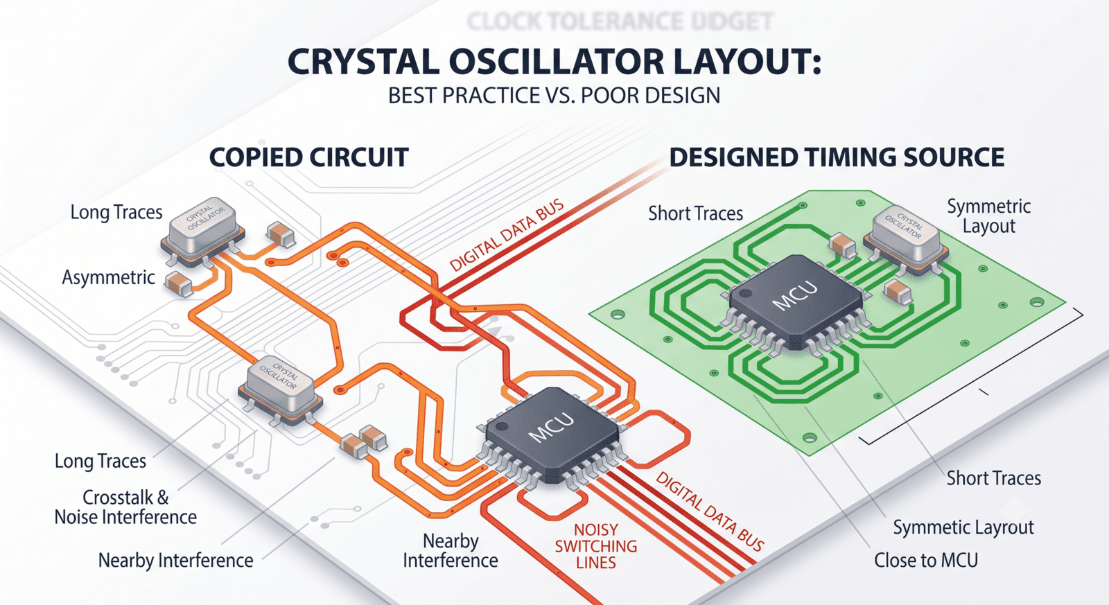
A good architecture does not treat the crystal circuit as a copied block.
It treats it as a calibrated timing source.
That means the layout must be quiet. The traces should be short and symmetrical. The ground reference should be stable. Fast digital traces should not pass under or near the oscillator region. The capacitor values should be chosen from the crystal load requirement and the actual board environment, not from habit.
The crystal is small, but it is not casual.
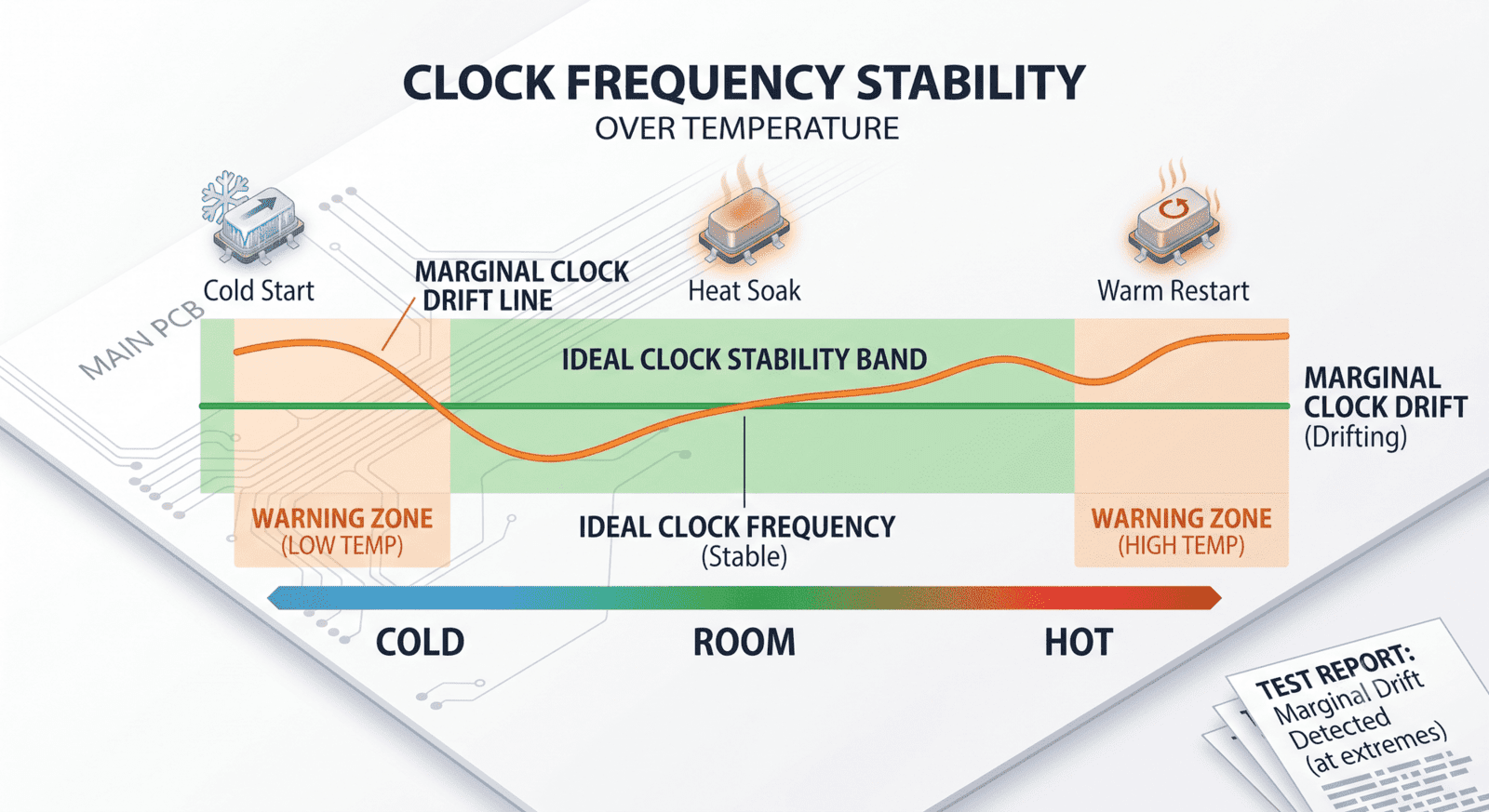
Temperature Drift Turns Marginal Clocks Into Field Bugs
A clock that works at room temperature can still be weak.
Many systems are validated on a bench, in a comfortable lab, with a stable power supply and known ambient conditions. The clock starts. The PLL locks. The firmware runs. The design is considered fine.
Then the product experiences a cold morning, direct sunlight, enclosure heating, nearby regulators warming the PCB, or repeated thermal cycling.
The crystal frequency shifts. The oscillator startup time changes. The PLL may take longer to lock. A peripheral expecting a stable reference may be released too early. A communication link may move closer to its timing limit.
These are not dramatic failures. They are the worst kind of failures: intermittent, unit-dependent, and difficult to reproduce.
At Hoomanely, we treat temperature as part of clock validation, not only thermal validation.
The clock tree should be tested across cold start, hot start, temperature ramp, and steady-state heat soak. The goal is not only to check whether the MCU boots. The goal is to check whether every subsystem that depends on the clock behaves correctly when the timing source is at its worst condition.
If the crystal drifts but the system still has margin, the design is robust.
If the system works only when the crystal behaves ideally, the design is waiting for a field issue.
PLL Lock Is Not the Same as Clock Readiness
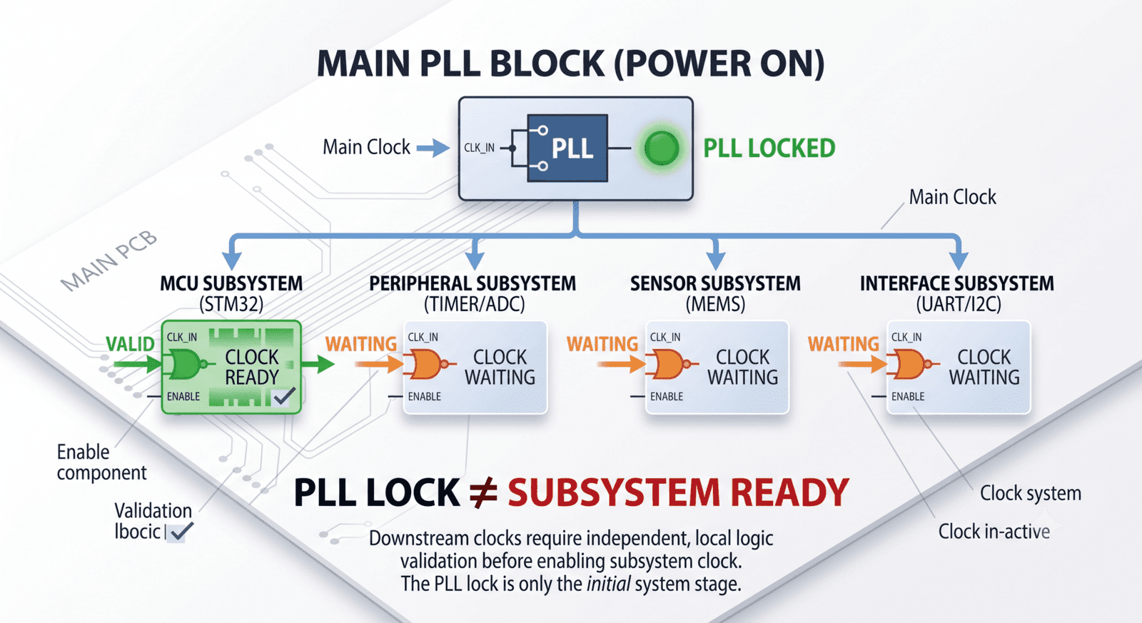
PLL lock is often treated as a simple firmware checkpoint.
Enable the oscillator.
Enable the PLL.
Wait for the lock flag.
Switch system clock.
Continue boot.
That flow is common, but it is not always sufficient.
A PLL lock flag tells you that the PLL believes it has locked. It does not automatically mean every downstream clock domain is safe, every divider is correct, every peripheral has a valid clock, or every external subsystem is ready to receive timing.
A system clock may be valid while a peripheral clock remains disabled. A high-speed interface reference may need additional stabilization. A sensor may require a clock before reset release, but only after power is valid. A camera may need a precise clock sequence before configuration. A communication interface may need both clock validity and voltage-domain readiness before traffic begins.
In a reliable clock tree, PLL lock is one milestone.
It is not the final permission.
The clock tree should expose or internally enforce a stronger concept:
clock valid for this subsystem.
That means the specific clock source, divider, PLL, mux, gate, power rail, and reset state required by that subsystem are all valid together.
Without that discipline, firmware may start a peripheral because the main PLL is locked, while the actual local timing environment is still incomplete.
Clock-Valid Gating Prevents Premature Subsystem Activity
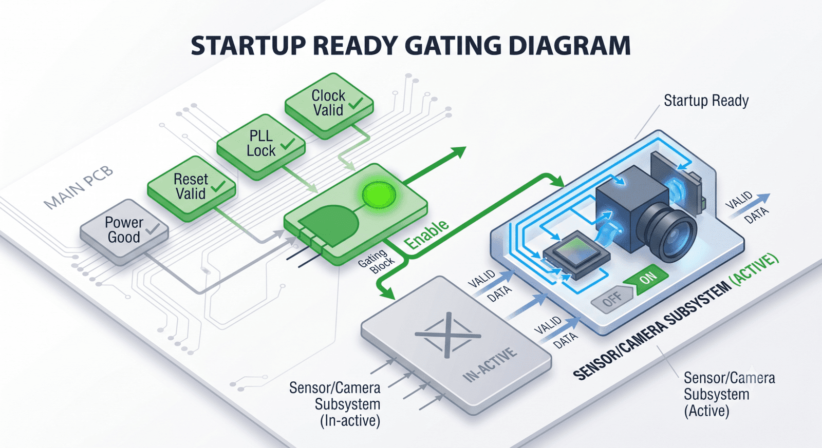
Clock-valid gating is one of the cleanest ways to prevent startup races.
A peripheral should not start simply because its power rail is present. It should not start simply because reset is released. It should not start simply because firmware has reached a line of code.
It should start only when its clock is valid.
This matters especially for interfaces that are sensitive during initialization: cameras, audio codecs, ADC sampling paths, communication transceivers, external memory, and sensor timing circuits.
Clock-valid gating can be implemented in different ways. Sometimes it is a firmware state machine. Sometimes it is a hardware enable signal. Sometimes it is a combination of power-good, reset control, clock-enable, and peripheral-ready sequencing.
The exact implementation depends on the product, but the principle stays the same:
No clock validity, no activity.
This avoids a common failure pattern where a subsystem wakes into undefined timing, misreads configuration, locks into a bad state, and then requires a full power cycle to recover.
A gated clock tree makes invalid timing difficult to use.
That is the kind of protection we prefer.
Fallback Oscillator Paths Are Not Only for Emergency Boot
Fallback oscillators are often seen as backup tools.
If the crystal fails, use the internal oscillator.
If the external clock does not start, fall back to a safe clock.
If the PLL does not lock, boot slowly.
That is useful, but the fallback path can do more.
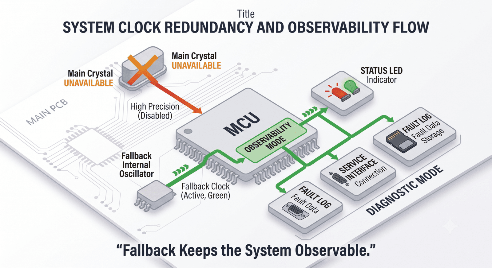
It can make the system observable.
A product with a fallback oscillator can still report that the main crystal failed. It can enter service mode. It can keep a basic interface alive. It can avoid appearing completely dead. It can log the failure, blink a meaningful pattern, or allow firmware recovery.
Without fallback timing, a crystal failure may look like a dead board.
That makes factory debugging slower and field diagnosis harder.
At Hoomanely, we think the fallback clock should support controlled degraded behavior. It may not run the full application. It may not support every interface. It may not meet precision requirements. But it should be enough to bring the system into a known diagnostic state.
The fallback path should answer a simple question:
“What can the device still do if the main timing source is not trustworthy?”
If the answer is “nothing,” then the clock tree has become a single point of silence.
Clock Failures Need Clear Recovery Behaviour
A weak clock tree does not know what to do when timing becomes invalid.
It may hang.
It may retry forever.
It may continue running with an unstable clock.
It may partially enable features.
It may reset repeatedly without explanation.
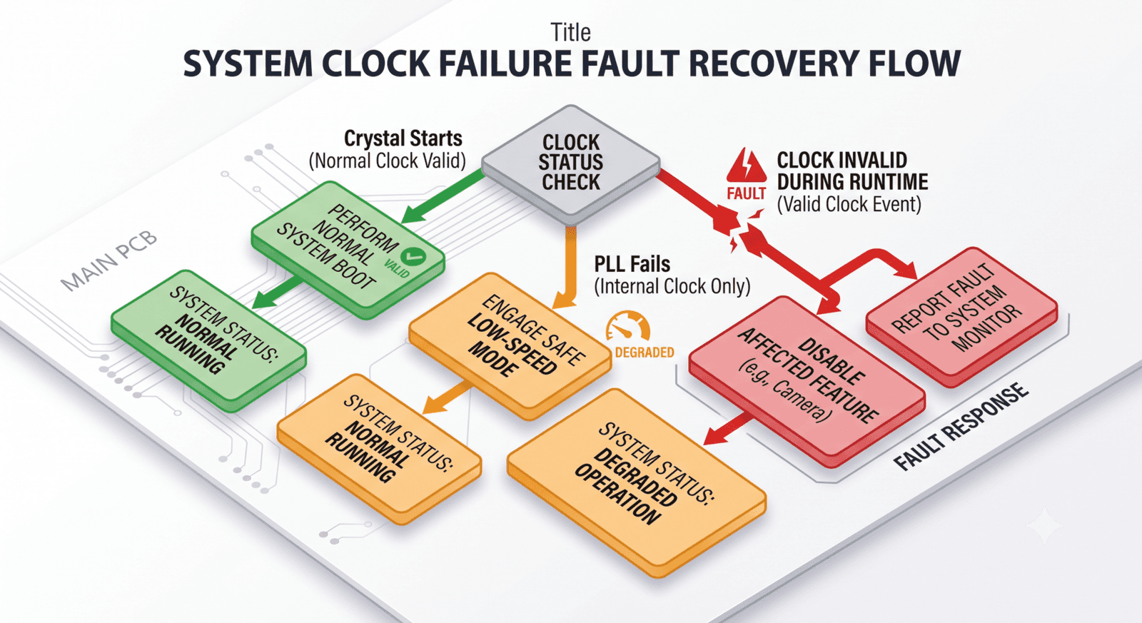
A strong clock tree has a recovery policy.
If the crystal does not start within the expected window, the system falls back. If the PLL does not lock, the system avoids high-speed operation. If a peripheral reference clock is invalid, that feature remains unavailable. If clock failure happens during runtime, the system moves to a safe state rather than pretending everything is normal.
This does not require excessive complexity. It requires ownership.
Someone in the architecture must decide what each subsystem is allowed to do when its timing source is missing, drifting, or not yet valid.
For example:
- the MCU may boot from internal oscillator,
- high-speed links may remain disabled,
- sensor sampling may pause,
- timestamp-sensitive data may be marked invalid,
- field diagnostics may report clock failure,
- and recovery may require controlled reinitialization.
The important point is that clock failure should not produce random product behavior.
It should produce a defined state.
Do Not Share a Clock Without Sharing Responsibility
Clock distribution is attractive.
One oscillator feeds multiple parts of the system. One reference clock supports several peripherals. One main PLL drives many internal domains. This reduces component count and can improve synchronisation.
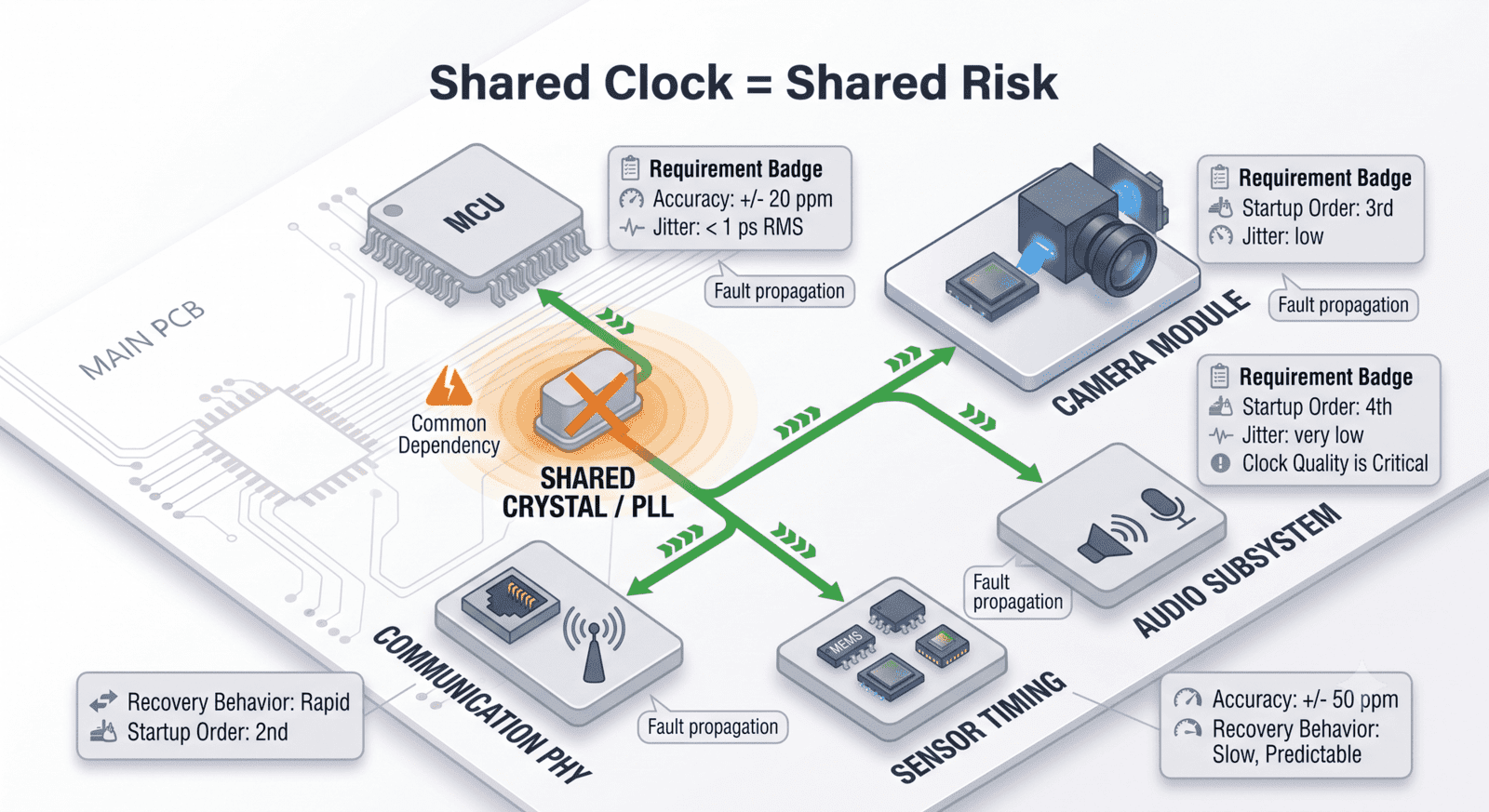
But shared clocks create shared failure modes.
If one clock feeds the processor, camera, communication interface, and sensor timing path, then drift or startup failure affects all of them. A routing issue, load issue, or gating error can become a system-wide fault.
This does not mean shared clocks are bad. It means shared clocks need shared responsibility.
Each consumer should be reviewed for tolerance, startup dependency, acceptable jitter, recovery behaviour, and failure consequence. If one consumer needs a very precise reference and another only needs a rough clock, the architecture should not blindly assume one source satisfies both without margin.
The clock tree should show not only where clocks go, but what each destination expects.
A clock net is not just a connection.
It is a promise.
Validate Clock Trees Under Real Startup Conditions
Clock validation should not stop at measuring frequency on a bench.
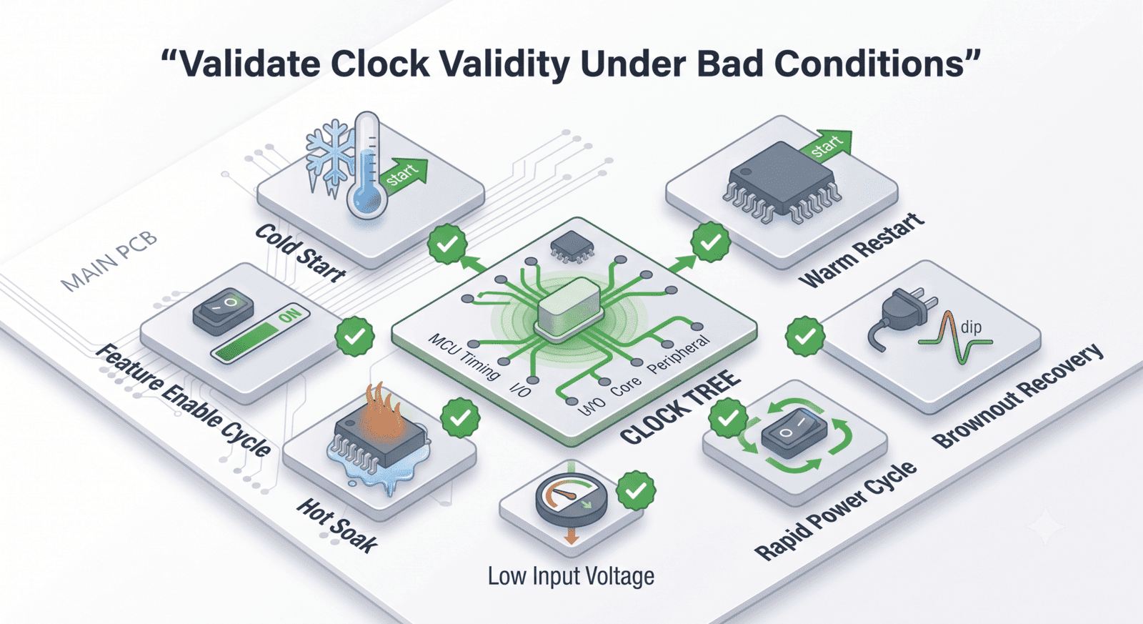
A clock tree should be tested during the moments where it is most vulnerable:
- first cold start,
- warm restart,
- brownout recovery,
- rapid power cycling,
- low input voltage,
- high temperature,
- cold temperature,
- peripheral enable/disable cycles,
- and simultaneous feature startup.
These conditions reveal issues that nominal probing often misses.
For example, a crystal may start correctly after a full power-off but fail after a short power interruption. A PLL may lock reliably at room temperature but take longer at cold. A peripheral may need its reference clock before reset release, but only under certain power ramp rates. A fallback oscillator may work in firmware but fail to preserve the correct diagnostic path.
The validation goal is not only “clock present.”
The goal is:
“Clock valid at the right time, for the right subsystem, under the wrong conditions.”
That is the standard that prevents field surprises.
Hoomanely’s View: Clock Trees Are Trust Trees
At Hoomanely, we see a clock tree as a trust tree.
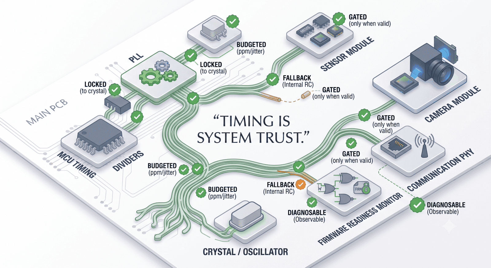
Every subsystem that depends on timing is trusting the source above it. The MCU trusts the crystal. The PLL trusts the oscillator. The peripheral trusts the divided clock. The sensor interface trusts the enable timing. The firmware trusts the lock flag. The user trusts the product to behave consistently.
If any part of that chain is assumed rather than verified, the product becomes fragile.
A good clock tree does not only generate frequency.
It proves timing readiness.
It contains drift within budget.
It watches lock state.
It gates activity until clocks are valid.
It provides fallback paths.
It fails into a diagnosable state.
That is the difference between a clock circuit and a clock architecture.
Final Thoughts
Clock trees fail quietly when they are treated as background details.
Crystal tolerance, temperature drift, PLL lock timing, fallback oscillator behavior, and clock-valid gating all decide whether a product starts reliably and stays stable across real operating conditions.
A good design does not assume the crystal is perfect. It budgets the error. It does not assume PLL lock means all clocks are ready. It verifies local timing readiness. It does not let subsystems run on questionable timing. It gates them. It does not turn clock failure into silence. It provides a fallback path.
The hardware may only show a small crystal and a few capacitors.
But the product depends on that tiny circuit to keep time honest.
At Hoomanely, we design clock trees to survive the real world, not just oscillate on the bench.
Because timing is not a support function.
Timing is system trust.



