Component Libraries Done Right: Library Hygiene in the vBus Ecosystem
Introduction: The Foundation of Design Quality
At Hoomanely, every PCB design begins with component libraries—the schematic symbols, PCB footprints, and 3D models that represent physical components in our EDA tools. Poor library hygiene creates ripple effects: incorrect footprints require PCB respins, missing pins cause assembly issues, inconsistent naming slows design reviews. Excellent library hygiene does the opposite: accelerates design, prevents errors, and enables seamless collaboration across our engineering team.
As our vBus product portfolio has scaled, we've developed a systematic approach to component library management. This isn't just documentation—it's operational discipline that enables new hardware designers to be productive immediately, ensures design consistency across modules, and maintains quality as our component library grows beyond thousands of parts.
Today, I want to share our library hygiene framework—the standards, workflows, and automation that make component libraries a competitive advantage rather than a source of friction.
The Library Structure: Organization for Scale
Three-Tier Architecture
Our component libraries follow a hierarchical structure:
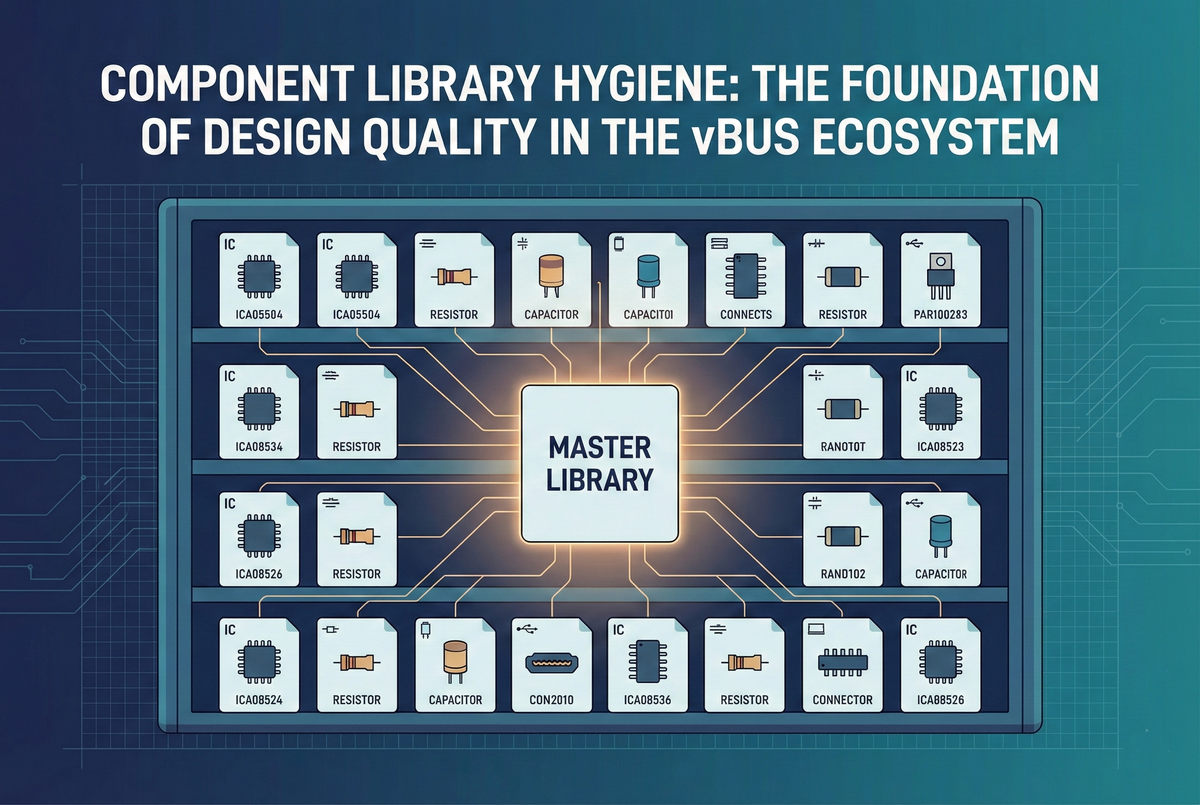
Master Library: Company-wide approved components. Every part verified, footprint validated, used in production designs. This is the single source of truth—designers start here.
Project Library: Module-specific components not yet in master library. Parts under evaluation, prototype-only components, or variants awaiting validation. These promote to master after successful production use.
Personal Library: Individual designer workspace for experimentation. Never used in production designs without review and promotion to project or master library.
This hierarchy ensures quality control while enabling flexibility during development.
Naming Convention
Every component follows standardized naming:
Format: [Category]_[Manufacturer]_[PartNumber]_[Package]
Examples:
IC_STM_STM32H743ZIT6_LQFP144
IC_TI_TPS62840DLCR_WSON8
Resistor_Yageo_RC0603FR-071KL_0603
Capacitor_Murata_GRM188R71C104KA01D_0603
Connector_Molex_503480810_8Pin
This naming immediately communicates:
- Component category (IC, passive, connector, etc.)
- Manufacturer (no ambiguity about source)
- Exact part number (full manufacturer designation)
- Package type (physical form factor)
Benefits: Designers find components quickly, BOM generation is automatic, duplicate components are immediately obvious.
Component Creation Standards
Schematic Symbol Requirements
Pin Naming: Every pin labeled with functional name, not just pin number:
- Good:
VDD,UART_TX,I2C_SDA,GPIO_15 - Avoid:
Pin 1,Pin 2,P1.5
Pin Grouping: Related pins grouped logically:
- Power pins together (VDD, VCC, GND)
- Communication interfaces grouped (all I2C pins adjacent)
- GPIO banks organized by port
Pin Ordering: Functional arrangement, not physical package order—symbol layout optimizes schematic readability, not matching chip pinout.
Visual Standards:
- Standard rectangular symbol for ICs
- Power pins at top, ground pins at bottom (matches typical schematic flow)
- Inputs on left, outputs on right (signal flow left-to-right)
- Pin spacing: 100 mil (0.1") grid standard
Metadata: Every symbol includes:
- Manufacturer and part number in properties
- Description (component function in 1-2 sentences)
- Datasheet URL hyperlink
- Footprint assignment (linked to correct PCB footprint)
PCB Footprint Requirements
Dimensional Accuracy: Footprints created from manufacturer drawings, not approximations:
- Pad sizes match recommended land pattern
- Pad spacing verified against tolerance stack-up
- Courtyard outline encompasses maximum component dimensions
- Component origin at geometric center or pin 1 (consistently applied)
Pad Naming: Pad numbers/names match schematic symbol pins exactly—enables electrical rule checking and prevents net misconnections.
Silkscreen:
- Component outline visible (outside pad areas)
- Pin 1 indicator clearly marked (dot, triangle, or square)
- Reference designator position standardized (top-left of outline)
- Polarity indicators for polarized components
Assembly Information:
- Courtyard layer defines component keep-out zone
- Component height specified (for mechanical clearance checking)
- Orientation reference (0° rotation standard defined)
Validation: Every footprint verified against:
- IPC-7351 land pattern calculator (standard pad geometry)
- Manufacturer recommended footprint (from datasheet)
- Physical component measurement (for critical or non-standard parts)
3D Model Integration
3D STEP Models: Every component includes 3D model when available:
- Downloaded from manufacturer or component aggregator (SnapEDA, Ultra Librarian)
- Positioned and scaled correctly relative to footprint
- Enables mechanical interference checking before prototyping
Model Sources:
- Manufacturer website (highest accuracy)
- Component distributors (Digi-Key, Mouser provide models)
- Third-party libraries (SnapEDA, SamacSys)
- Generic models for simple parts (passives, standard connectors)
The Component Lifecycle
New Component Request
When designer needs component not in master library:
1. Search First: Check master and project libraries—component may already exist under different manufacturer part number (alternate source).
2. Reuse When Possible: If functionally equivalent component exists, use it unless specific requirement demands new part. Reduces library bloat and leverages existing validation.
3. Create in Project Library: New component created following standards, used in project design.
4. Peer Review: Another designer reviews symbol and footprint:
- Pin names correct and clear?
- Footprint dimensions match datasheet?
- 3D model properly aligned?
- Naming convention followed?
5. Prototype Validation: After successful PCB assembly and testing, component promoted to master library with validation notes.
Master Library Promotion
Components enter master library only after validation:
Criteria:
- Used in at least one successful prototype or production design
- Footprint verified via assembled PCB (component fits, solders correctly)
- No dimensional or electrical issues discovered
- Complete metadata (datasheet, description, manufacturer info)
- Peer review completed and approved
Process: Project library component copied to master, validation record attached, announcement to engineering team that new component available.
Version Control
Git-Based Library Management: Component libraries stored in version control:
- Every change tracked with commit message
- Designer attribution for accountability
- Revert capability if errors discovered
- Branch-based development for major changes
Semantic Versioning: Footprint changes tracked with version numbers:
- Major version: Footprint geometry change (breaks compatibility)
- Minor version: Silkscreen or cosmetic adjustment (compatible)
- Enables tracking which designs use which footprint version
Validation and Quality Control
Automated Checks
Library Validation Scripts: Automated tools check compliance:
Naming Validation: Script verifies component names follow convention, flags non-compliant entries.
Footprint Verification: Script checks:
- All pads have connections (no orphaned pads)
- Courtyard layer present
- Silkscreen doesn't overlap pads (manufacturing issue)
- Pin 1 indicator present
Symbol Completeness: Script verifies:
- Footprint assignment exists
- Datasheet URL populated
- Manufacturer and part number fields filled
- All pins have names (not just numbers)
Duplicate Detection: Script identifies potential duplicates (similar part numbers, identical footprints) for consolidation review.
Manual Review Process
Beyond automation, human review catches design intent issues:
Schematic Review: Does symbol layout enable clear schematics? Are pin names intuitive?
Footprint Review: Does land pattern match IPC recommendations? Any manufacturer-specific notes in datasheet addressed?
Usability Review: Is component easy to use in designs? Are there gotchas that should be documented?
Training and Onboarding
New Designer Onboarding
Library Training Module: New hardware engineers receive structured training:
Session 1 - Structure and Standards: Overview of library hierarchy, naming conventions, component lifecycle.
Session 2 - Creating Components: Hands-on creation of schematic symbol and footprint following standards, peer review practice.
Session 3 - Tools and Automation: Using validation scripts, accessing library in EDA tools, version control workflow.
Assignment: Create three components (IC, passive, connector) from datasheets, submit for review—validates understanding before production work.
Documentation
Living Style Guide: Comprehensive documentation covering:
- Component naming rules with examples
- Symbol creation guidelines with templates
- Footprint creation workflow with IPC references
- 3D model integration instructions
- Promotion process and criteria
Example Gallery: Library of exemplar components showing best practices—designers reference these when creating similar components.
vBus-Specific Library Standards
Connector Libraries
vBus connectors receive special treatment:
Standard Footprints: Each vBus connector type (16-pin, 40-pin, 50-pin, 100-pin) has validated master footprint—modifications require architecture review.
Pin Assignment Validation: Schematic symbols include pin-out verification—power pins highlighted, signal blocks color-coded, matches vBus specification.
Mechanical Integration: 3D models include proper mating connector clearances—enables verification that SOMs physically fit on carrier boards.
Module-Specific Components
CPU SoM Processors: Footprints include:
- Thermal pad connections defined
- Recommended via patterns for thermal vias
- Decoupling capacitor placement guidelines in footprint notes
Power SoM Components: High-current regulators include:
- Thermal relief patterns
- Wide pad designs for current handling
- Recommended copper pour outlines
Sensor Components: Environmental sensors include:
- Keep-out zones for sensing accuracy
- Orientation indicators (directional sensors)
- Environmental exposure requirements noted
Benefits: Velocity Through Standardization
Quantified Improvements
Design Speed: Validated components reduce design time:
- No footprint creation during schematic capture—library already has it
- No dimensional verification needed—footprint already validated
- Fewer PCB spins—footprints work first time
Onboarding Acceleration: New designers productive immediately:
- Clear standards reduce learning curve
- Example components provide templates
- Validation catches mistakes before they reach production
Cross-Team Consistency: All designers use same components:
- Design reviews faster (familiar component usage patterns)
- BOM consolidation easier (fewer part number variants)
- Manufacturing yields higher (proven footprints reduce assembly issues)
Error Prevention
Common Issues Eliminated:
- Incorrect pad sizes (footprints validated against datasheets)
- Wrong pin assignments (symbol review catches errors)
- Missing pins (automated checks flag incomplete symbols)
- Duplicate components (naming convention makes duplicates obvious)
First-Pass Success: Library hygiene contributes to our >95% first-pass PCB success rate—footprints work correctly on first manufactured revision.
Continuous Improvement
Feedback Loops
Designer Feedback: Engineers report library issues or suggestions:
- Component difficult to use? Guidelines updated.
- Footprint dimension concern? Re-verified and corrected if needed.
- Naming ambiguous? Convention refined with examples.
Manufacturing Feedback: Assembly house reports component issues:
- Solderability problems? Pad size adjusted.
- Component orientation confusion? Silkscreen improved.
- Clearance violations? Courtyard dimensions corrected.
Quarterly Library Audits
Review Sessions: Team reviews library health quarterly:
- Which components used most frequently? (Prioritize for extra validation)
- Which components never used? (Consider deprecation)
- What new component categories needed? (Proactive library building)
- Any validation gaps identified? (Address with new checks)
Conclusion: Libraries as Infrastructure
Component library hygiene isn't glamorous work, but it's foundational infrastructure that amplifies every design effort. When libraries are well-maintained—accurate footprints, clear naming, comprehensive validation—designers move faster, make fewer mistakes, and collaborate more effectively.
At Hoomanely, we've elevated library management from housekeeping to strategic capability. Our standardized approach enables new designers to hit the ground running, ensures consistency across our growing vBus portfolio, and contributes directly to our industry-leading first-pass success rates.
As our product ecosystem scales, our library infrastructure scales with it—new components integrate seamlessly, validation automation prevents degradation, and continuous improvement ensures quality compounds over time. This is engineering excellence in the details, and those details matter profoundly.


