Designing a Reliable Stop-and-Wait Transport Protocol on CAN FD for Deterministic Embedded Systems

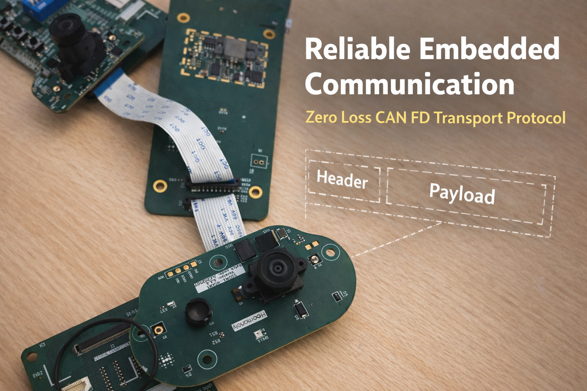
In high-performance embedded systems, data integrity and deterministic timing are paramount. Controller Area Network (CAN) has long been the standard for reliable automotive and industrial communication. With the transition to CAN FD (Flexible Data-rate), we gained higher bandwidth and larger payloads. However, standard CAN FD, while robust for short control messages, lacks a native transport layer for reliably transferring large datasets—such as thermal images or firmware updates—across a noisy bus without data loss.
This article details the design and implementation of a Reliable Stop-and-Wait Transport Protocol on top of CAN FD. We explore the challenges of embedded resource constraints, the evolution of our design to meet strict determinism requirements, and the architecture that achieves zero packet loss for critical sensor data.
The Problem: Beyond Standard CAN FD
Our application transmits high-resolution thermal sensor arrays (approximately 3KB of data) from a sensor node to a main controller. While 3KB is trivial in many contexts, in a hard real-time embedded system with limited RAM and shared bus bandwidth, it presents significant challenges.
1. The "Fire-and-Forget" Risk
Standard CAN is a broadcast protocol. A successful transmission on the bus does not guarantee successful processing by the receiver. If the receiving node is busy—erasing flash memory or handling high-priority interrupts—its receive buffers may overflow, leading to silent packet loss. Losing even a single fragment of a larger dataset invalidates the entire frame.
2. Burst Mode Congestion
Attempting to transmit the entire dataset in a continuous "burst" saturates the bus. This blocks other critical command-and-control messages, effectively freezing the system's communication for the duration of the transfer.
3. Verification Gaps
Without an application-level acknowledgment (ACK), the sender operates blindly. We needed a definitive contract: a guarantee that both Sender and Receiver remain synchronized throughout the transfer.
4. Deterministic Latency Requirements
Our system manages multiple high-speed sensors and safety loops. A transport protocol that monopolizes the bus unpredictably is unacceptable. We needed a mechanism that supports Priority granularity—the ability to pause or cancel a large transfer instantly if a higher-priority task, such as a user trigger, occurs.
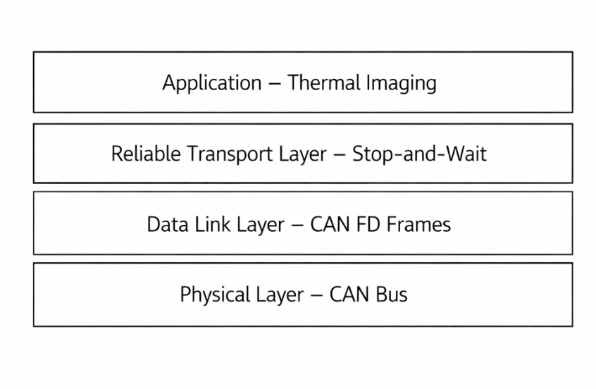
The Mechanics of Reliability
Why Stop-and-Wait?
Stop-and-Wait is often considered less efficient than Sliding Window protocols (like TCP) because it waits for an acknowledgment after every packet. However, this apparent inefficiency buys us State Simplicity.
In a memory-constrained environment (like a Cortex-M33), implementing a full Sliding Window requires complex reassembly buffers and state tracking for out-of-order packets. Stop-and-Wait flips the script:
- Sender: Manages the complexity (retries, timeouts, state).
- Receiver: Remains stateless and idempotent. It processes one packet at a time, immediately.
This architectural choice eliminates the need for large RAM buffers on the receiver and makes the system behavior highly predictable.
The Hardware Foundation
Our implementation leverages a modern microcontroller series and a robust CAN FD transceiver. The physical layer features Signal Improvement Capability (SIC), allowing us to push the data phase bit rate to 5 Mbps robustly. We configure the CAN FD timing with Transceiver Delay Compensation (TDC) to account for propagation delays at these high speeds. A solid physical layer is the prerequisite for any reliable software protocol.
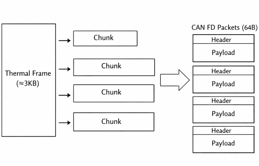
Protocol Architecture
The protocol structures the data into a hierarchy to manage flow and storage:
- Chunks: The large dataset is divided into manageable blocks (e.g., aligned with flash memory page sizes).
- Packets: Each chunk is further sliced into CAN FD frames, utilizing the maximum 64-byte payload.
The Custom Header
Every packet carries a lightweight header to maintain context. This typically includes:
- Sequence Metadata: Current Packet Index, Total Packets, and Chunk ID.
- Command/Type: Identifies the data stream (e.g., Thermal, Firmware).
- System Timestamp: Ensures global time synchronization for the data.
This header allows the receiver to identify duplicate packets or detect missing sequences immediately.
The Logic Flow
The core reliability mechanism is a nested state machine on the sender side.
1. The Transmission Loop
Instead of a simple linear send, the logic follows a nested structure: Chunks -> Packets -> Retries.
Initialize Transfer
For Each Chunk:
For Each Packet in Chunk:
Reset Retry Counter
While (ACK Not Received) AND (Retry Count < Max):
1. Construct Packet (Header + Data)
2. Transmit via CAN FD
3. Wait for ACK (with Timeout)
If ACK Received:
Break Loop (Success)
Else:
Increment Retry Count
Backoff Delay (Give receiver time)
If Timeout Reached:
Abort Transfer (Error)
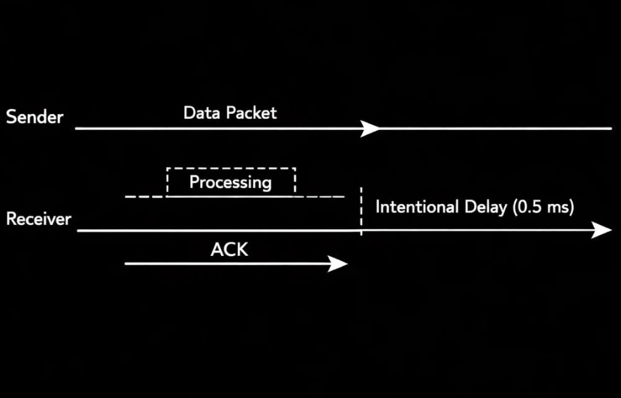
Small Delay (Flow Control)2. The ACK Handshake
When the receiver successfully processes a packet (e.g., stages it for flash writing), it replies with a specific ACK message. The sender waits for this ACK before proceeding. This strict handshake closes the verification loop for every single segment of data.
3. Priority Cancellation (The "Yield" Feature)
Crucially, the "Wait for ACK" phase is not a blocking sleep. It is an active check that also monitors for System Cancellation Requests. If a high-priority event (like a snapshot trigger) occurs, the protocol detects it inside the wait loop and aborts immediately. This ensures the background transfer never blocks a critical foreground action for more than the time of a single packet (milliseconds).
The Receiver's Role: Idempotency
The receiving side is designed to be idempotent—handling the same packet multiple times without corruption.
- Scenario: A packet is received and written, but the ACK is lost. The sender re-transmits.
- Handling: The receiver checks the Packet Index. If it sees the packet has already been processed, it discards the data but resends the ACK. This unblocks the sender without corrupting the data stream.
Why Not ISO-TP?
We considered using ISO-TP (ISO 15765-2), the standard for automotive diagnostics. However, we opted for a custom solution for specific reasons:
- Overhead: ISO-TP flow control can be overly chatty for unidirectional sensor streaming.
- Complexity: A full ISO-TP stack is heavy. Our solution is streamlined (<300 lines) and easier to validate.
- Control: We needed deep hooks for "Priority Cancellation." Integrating application-layer abort logic into a third-party ISO-TP stack is often invasive and complex.
For our specific use case—unidirectional, high-bandwidth sensor streaming—a custom "ISO-TP Light" approach provided better performance and simpler integration.
Performance & Optimization
Bandwidth vs. Reliability
- Theoretical: At 5 Mbps, a 3KB transfer could take ~5ms.
- Actual: With Stop-and-Wait overhead, ACK round-trips, and intentional flow-control delays, it takes ~30-40ms.
While this is slower than the theoretical maximum, it is a calculated trade-off. For a system running at 4Hz (250ms per frame), spending 40ms on reliable transfer leaves 84% of the CPU budget free. We sacrifice raw speed for 100% reliability and system stability.
Data Compression
To maximize throughput, we apply domain-specific compression. Thermal data is often floating-point, but sensors have a noise floor. By converting 32-bit floats to 16-bit fixed-point values (e.g., scaling by 100), we double our effective bandwidth while maintaining sufficient precision for the application.
Conclusion
Building a reliable transport protocol on CAN FD requires respecting the physical realities of the bus and the resource constraints of the microcontroller. By implementing a deterministic Stop-and-Wait mechanism with robust error handling and priority awareness, we transformed a "best-effort" bus into a reliable data pipeline. The result is a system where critical sensor data moves with absolute certainty, without compromising the responsiveness of real-time control loops.
In the world of high-performance embedded systems, data integrity and deterministic timing are paramount. Controller Area Network (CAN) has been the backbone of reliable automotive and industrial communication for decades. With the advent of CAN FD (Flexible Data-rate), we gained higher bandwidth and larger payloads (up to 64 bytes). However, standard CAN FD, while robust for short control messages, lacks a native transport layer for reliably transferring large datasets—such as thermal images or firmware updates—across a noisy bus without data loss.
This article details our journey in designing and implementing a Reliable Stop-and-Wait Transport Protocol on top of CAN FD. We discuss the challenges of embedded resource constraints, the evolution of our design, and the technical implementation that allows us to transmit high-resolution thermal data with zero packet loss in a deterministic real-time environment.
The Problem: Beyond Standard CAN FD
Our application required transmitting a thermal image array consisting of 768 floating-point values (approx. 3KB of data) from a sensor node to a main controller. While 3KB sounds trivial in web development, in a hard real-time embedded system with 8Mbps CAN FD links and limited RAM, it presents significant challenges.
1. The "Fire-and-Forget" Risk
Standard CAN is a broadcast protocol. You put a frame on the bus, and if no error flag occurs, you assume it's sent. However, "sent" does not mean "processed." If the receiver is busy writing to flash or handling an interrupt, its RX FIFO might overflow, leading to silent packet loss. Losing even a single 64-byte chunk of a thermal image invalidates the entire frame.
2. Burst Mode Congestion
Attempting to blast 3KB of data back-to-back saturates the bus. This "burst mode" approaches blocks other critical command-and-control messages, effectively freezing the system's nervous system for the duration of the transfer.
3. Verification Gaps
Without an application-level acknowledgment, the sender has no way of knowing if the receiver successfully reconstructed the data. We needed a contract: a guarantee that Sender and Receiver obey a strict state machine.
4. Deterministic Latency Requirements
In our system, the thermal camera is not the only actor. We have high-speed image sensors, time-of-flight modules, and critical safety loops. A transport protocol that hogs the bus for 100ms unpredictably is unacceptable. We needed a mechanism that could "yield" or be cancelled instantly if a higher-priority task (like a snapshot trigger) occurred. The standard "blast and hope" approach offers no such granularity.
The Mechanics of Reliability: A Deep Dive
Why Stop-and-Wait?
In networking theory, Stop-and-Wait is often dismissed as inefficient compared to Sliding Window protocols (like TCP). In a Sliding Window, the sender blasts multiple packets before waiting for an acknowledgment, maximizing pipe utilization. However, this efficiency comes at a cost: State Management.
To implement a Sliding Window, the receiver needs a reassembly buffer to handle out-of-order packets and a complex state machine to track "Received," "Missing," and "Buffered" ranges. On a Cortex-M33 with limited RAM, dedicating tens of kilobytes to a transport buffer is a luxury we often cannot afford.
Stop-and-Wait flips the script. By enforcing a strict "Send 1 -> Wait -> Send Next" cadence, we eliminate the need for a reassembly buffer. The receiver processes the packet immediately upon arrival (or rejects it), and the sender holds the state. This shifts the complexity to the Sender, which is often the more powerful node (or at least, the one driving the transaction), and keeps the Receiver implementation nearly stateless.
The Hardware Layer: STM32H5 and TCAN1463
Our implementation runs on top of the STM32H5 series microcontrollers, utilizing the TCAN1463-Q1 transceiver. This is not a trivial detail. The TCAN1463 supports Signal Improvement Capability (SIC) and Wake-up on Pattern (WUP), allowing us to push the bit rate to 5 Mbps (data phase) reliably even on complex topology.
We configure the FDCAN peripheral with specific timing adjustments:
- Arbitration Phase: 1 Mbps (Standard CAN compatibility)
- Data Phase: 8 Mbps (Fast payload transfer)
- Transceiver Delay Compensation (TDC): Essential at 8 Mbps to account for propagation delay.
This physical layer robustness provides the foundation. If the bit-level transmission isn't solid, no amount of software retry logic will save you.
The Receiver's Perspective: Stateless Simplicity
While the sender handles retries, timers, and backoffs, the receiver's job is to be fast and idempotent.
The Idempotency Requirement
In a transport protocol, specific failure modes can lead to duplicate packets. Scenario: Sender sends Packet X. Receiver gets it, writes to flash, sends ACK. The ACK frame is corrupted on the bus. Sender times out and resends Packet X. If the receiver blindly accepts Packet X again, the thermal image will have a glitch (duplicate data).
Our receiver uses the Packet Index and Chunk ID from the header to de-duplicate.
- Check Context: Is
Packet_ID == Expected_ID? - If Match: Process data, increment
Next_Expected_ID, Send ACK. - If Old (Duplicate): Ignore data, BUT Send ACK.
- Why send ACK? Because the sender is evidently stuck waiting for it. Resending the ACK unblocks the sender.
- If Future (Gap): Reject (or buffer if memory allows, but in Stop-and-Wait this shouldn't happen unless we missed a reset).
Zero-Copy Pipeline
To achieve the 5Mbps throughput, the receiver cannot afford memcpy chains via the CPU.
- Direct Register Read: The FDCAN peripheral writes to its SRAM.
- Process Header: CPU checks the ID.
- Flash Write: If valid, the payload is staged for the next flash page write.
- ACK: A dedicated "Control/Event" CAN message is queued locally.
Alternatives Considered: Why Not ISO-TP?
Experienced automotive engineers might ask: "Why build a custom protocol when ISO-TP (ISO 15765-2) exists?"
ISO-TP is the standard for diagnostics (UDS) and has a transport layer. We evaluated it but rejected it for three reasons:
- Overhead: ISO-TP is designed for fragmentation of messages up to 4GB, but its flow control (FlowControl separation time mechanisms) is often too conservative or interactive for fixed-rate sensor streaming.
- Complexity: Implementing a compliant ISO-TP stack takes significant code space and validation. Our custom protocol is < 300 lines of Code.
- Granularity: ISO-TP abstracts the transport. We needed the ability to "pause" or "abort" essentially at the byte level from the application layer to handle the "Snapshot Priority" feature. Integrating such deep hooks into a third-party ISO-TP stack would have been messy.
Our solution is "ISO-TP Light" – optimized specifically for unidirectional sensor streaming rather than bidirectional request-response diagnostics.
Justification of Design Choices
Why 256-float Chunks? Flash memory pages on our target are often 256 bytes or multiples thereof. By aligning our chunks to 256 values (which pack to 512 bytes), we align naturally with the receiver's storage cadence. It's a "magic number" derived from the hardware reality, not arbitrary choice.
Why 16-bit Fixed Point? Thermal sensors like the output data with noise around 0.1°C to 0.4°C. transmitting 32-bit floats provides unnecessary precision (e.g., 25.123456°C). By scaling by 100 and casting to int16_t, we cover the range -327.68°C to +327.67°C with 0.01°C resolution. This compression creates a 2x bandwidth multiplier effectively for free.
The "Priority Cancellation" Pattern In standard protocols, a transfer is all-or-nothing. You can't stop a file download halfway to browse the web? Actually, you can, but embedded protocols often block. We inserted the g_transmission_cancel_requested check into the deepest loops (the ACK wait loop). This ensures that if the user presses the "Capture Photo" button, the thermal background task yields within milliseconds, not seconds. This is the difference between a "laggy" product and a "snappy" one.
Performance Analysis
Let's look at the numbers.
Raw Data Volume:
- 768 pixels * 2 bytes/pixel = 1536 bytes of payload.
- Header overhead: 4 bytes per ~60 bytes of data (~6.6% overhead).
- Total Data on Wire: ~1650 bytes.
Throughput Calculation:
- CAN FD Baud Rate: 5 Mbps (5,000,000 bits/sec).
- Effective Throughput (conservative, 80% efficiency): ~4 Mbps = 500 KB/s.
- Theoretical Transfer Time: 1650 bytes / 500,000 bytes/sec ~= 3.3 ms.
Measured Reality: In practice, our logs show a transfer time of ~30-40 ms. Why the discrepancy?
- ACK Round-Trip: The Stop-and-Wait adds a round-trip time (RTT) for every packet.
- Software Delays: The intentional
0.5mspacket delay and2mschunk delay add up.- ~26 packets * 0.5ms = 13ms delay.
- 3 chunks * 2ms = 6ms delay.
- Total intentional delay = ~19ms.
- OS Jitter: FreeRTOS context switching adds microseconds here and there.
Is 40ms Bad? For a 4Hz thermal camera (250ms period), a 40ms transfer consume 16% of the frame budget. This leaves 84% of the time free for image processing, ML inference, and other tasks. The trade-off is calculated and acceptable. We sacrificed ~3ms theoretical speed for 100% reliability and system stability.
Evolution of the Protocol
This wasn't Version 1.
Version 1: The Firehose We started by blasting CAN FD frames as fast as HAL_FDCAN_AddMessageToTxFifoQ would allow. Result? The receiver's FIFO overflowed immediately. We lost 40% of packets randomly.
Version 2: The Blind Wait We added vTaskDelay(1) between packets. Reliability improved to 99%, but we still had "hiccups" when the receiver was erasing flash sectors. 99% isn't good enough for data streams where 1 missing byte corrupts the file.
Version 3: The Handshake (Current) We introduced the return channel (ACK). This closed the loop. Now, if the receiver is erasing flash and pauses for 50ms, the sender simply waits (up to 20s!). No data is lost; it is just delayed. This elasticity is crucial for "heterogeneous workloads" where tasks take variable time.
Conclusion
Building a reliable transport protocol on CAN FD is about obeying the constraints of the medium. By accepting the overhead of headers and ACKs, we trade a small amount of throughput (3ms vs 40ms) for absolute guarantees of delivery. The result is a system that feels solid—thermal images arrive perfectly every time, regardless of what else the CPU is doing.
For embedded engineers facing similar challenges: stop trusting the bus. Verify everything. Reliability is not an accident; it is an engineered feature.


