Designing Around ToF Sensors for Reliable Performance
Introduction
Time-of-Flight sensors promise simple, accurate distance measurement: drop one into a design, read the distance, trigger some behavior. But inside a real, enclosed product, proximity sensing quickly turns into a mechanical and optical systems problem, not just an electrical one.
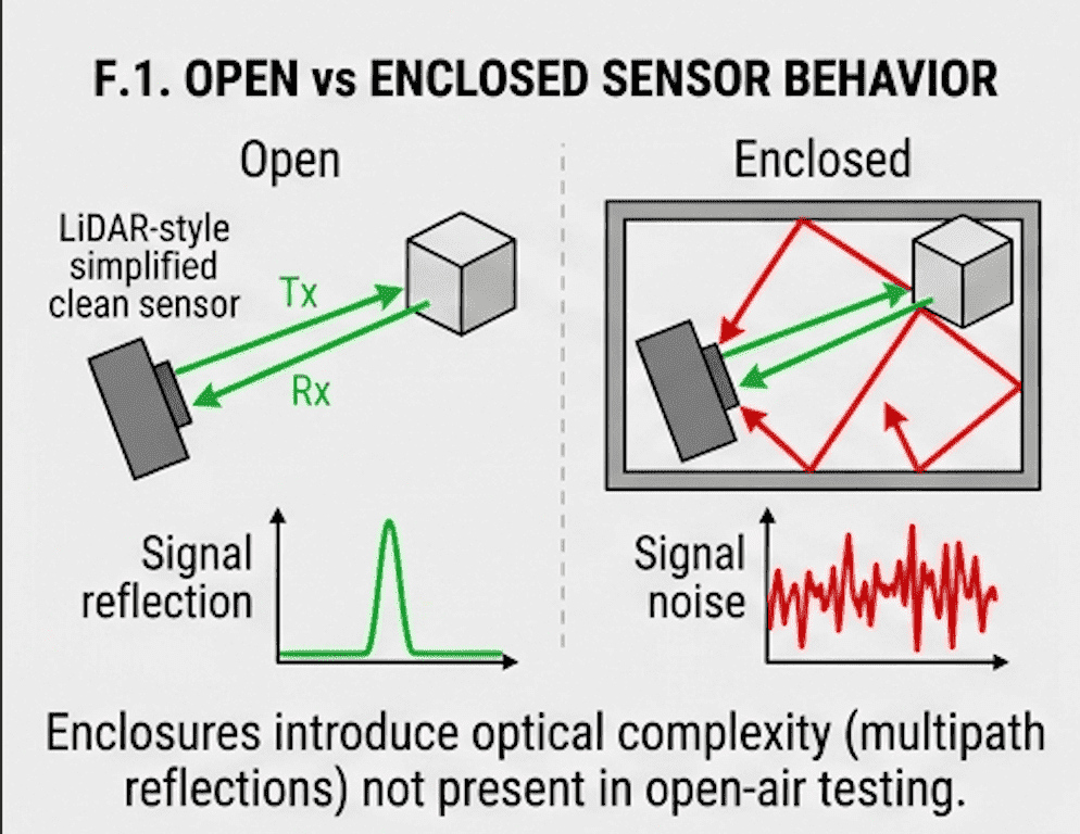
While working with the VL53L1X ToF sensor at Hoomanely, what worked perfectly on the bench started failing once it went inside the enclosure. Stable readings turned into mistriggers, noise, and unpredictable behavior. The root cause wasn't firmware, and it wasn't calibration. It was optical crosstalk induced by the enclosure itself. This post walks through how a working sensor became unstable, what actually caused it, and how we redesigned the system to fix it.
Worked on the bench, drifted inside the enclosure
The setup used a VL53L1X Time-of-Flight sensor with an operating range of roughly 7 to 50 cm and a field of view around a 27° cone. In open conditions, readings were stable and detection was consistent. Once installed inside the enclosure, false triggers appeared and detection got noisy. The system didn't fail outright, it became unpredictable, which is arguably worse.
Root cause: optical crosstalk
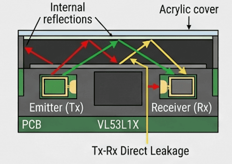
The key insight was that the sensor was detecting its own reflected light, not just the actual target. That phenomenon is called optical crosstalk, and here it came from internal reflections off the plastic walls, reflections off the acrylic cover, direct leakage from the transmitter straight to the receiver, and air gaps causing multi-path scattering. Even small reflections inside a compact enclosure can badly distort ToF readings.
ToF sensors are optical systems, fundamentally
A ToF sensor works by emitting infrared light, measuring the time it takes to reflect back, and converting that into distance. That means anything that reflects IR affects the reading. Unlike a simple IR proximity sensor, a ToF sensor is extremely sensitive to surface finish, geometry, and how well the optical path is controlled.
What we observed
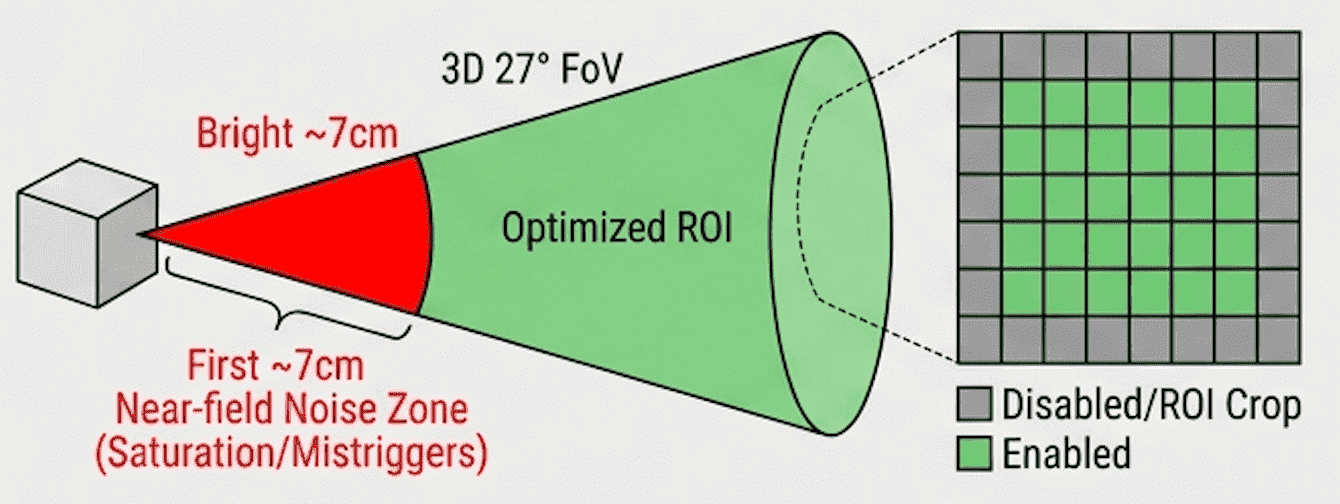
Near-field instability: distances below about 70 mm showed high instability, because strong reflections dominate, the sensor saturates with nearby signal, and crosstalk becomes significant. The fix was narrowing the detection range from 4 to 50 cm, which was unstable, to 7 to 50 cm, which held steady.
Air gap sensitivity: with the acrylic flush against the housing (0 mm gap), readings were stable; with the acrylic offset by around 8 mm, they weren't. Air gaps create multiple reflection paths, scatter the signal, and cost you optical control, so even a few millimeters of gap changed behavior dramatically.
Treating the enclosure as part of the sensor
The key shift in thinking was to stop treating the sensor as an isolated component and start treating the enclosure as part of the optical system. Instead of tuning firmware, we redesigned the optical environment around the sensor.
What actually fixed it
Black coating, the single most impactful change: painting internal surfaces matte black cut IR reflections and absorbed stray light, which noticeably reduced false triggers and cleaned up the signal.
Controlled aperture design: a straight hole acts like an optical tunnel and reflects light straight back into the sensor. A countersunk hole redirects stray light outward instead, cutting internal reflection.
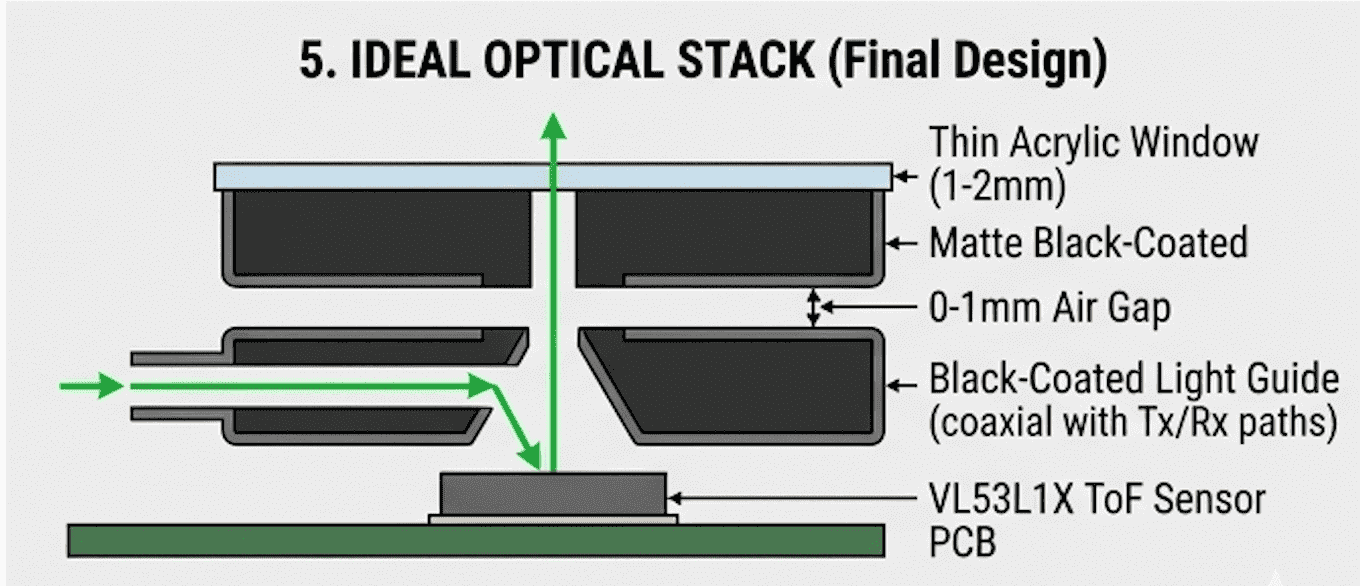
A light guide: we used a 6 mm diameter, 7.5 mm long acrylic light guide, coated black on the outside. It acted as an optical isolator blocking side reflections, a controlled path guiding IR forward, and a noise filter reducing stray light, turning a chaotic optical environment into a predictable signal path. The result was stable readings, less noise, and consistent behavior.
Minimizing air gap: we set a design rule of a 0 to 1 mm target gap and avoided floating windows entirely, which reduced scattering and improved signal integrity.
Optimizing the region of interest: excluding the near-field removed the dominant noise region and improved stability on its own.
From unstable to predictable
After all of this, false triggers dropped significantly, detection stabilized across different builds, and performance held consistent inside the enclosure. Most importantly, the system became predictable, not just functional.
Common mistakes to avoid
Testing only in open conditions, ignoring enclosure reflections, using large air gaps, treating ToF sensors like simple IR switches, and skipping optical isolation altogether all lead directly to unstable systems.
What this changed at Hoomanely
This experience shifted how we approach sensing systems overall: sensors aren't isolated components, mechanical design directly affects signal quality, and optical paths need to be intentionally designed, not left to chance. If your ToF sensor behaves differently inside the enclosure than it does on the bench, the enclosure is part of the problem, not the sensor.
The optical stack we settled on
- A thin acrylic window (1-2 mm) or a controlled light guide
- A minimal air gap (0-1 mm)
- Matte black internal surfaces
- A controlled aperture (roughly 3.5-4 mm near the sensor)
- Optional countersink geometry
Hoomanely context
At Hoomanely, building reliable interaction systems means designing beyond just the electronics. This proximity sensor challenge reinforced a principle we hold onto: real-world reliability comes from system-level thinking. By integrating mechanical design, optical behavior, and sensor logic together, the final system behaves consistently across environments in a way pure electrical tuning alone never could have achieved.
Conclusion
Proximity sensing looks simple until the enclosure closes around it. Something that works perfectly in open air can fail silently inside a product because of optical interactions nobody accounted for. The lesson is straightforward: design the light path, not just the electronics. Once the optical environment is controlled, the sensor becomes stable, predictable, and reliable. Until then, it stays a source of noise and frustration. Working with ToF sensors isn't really about picking the right module, it's about shaping how light behaves inside your product.
A cosplay wig is best compared by colour, length, fibre density and fringe shape. A wig cap can improve stability and keep natural hair contained. For styling and photo preparation, Marin Kitagawa styling wig(喜多川海夢 スタイリング用ウィッグ) provides the correct wig reference. Fit can be reviewed together with the wig cap and securing method. Comfort improves when the cap, hairline and securing points are adjusted carefully. A stand can help preserve volume after styling.