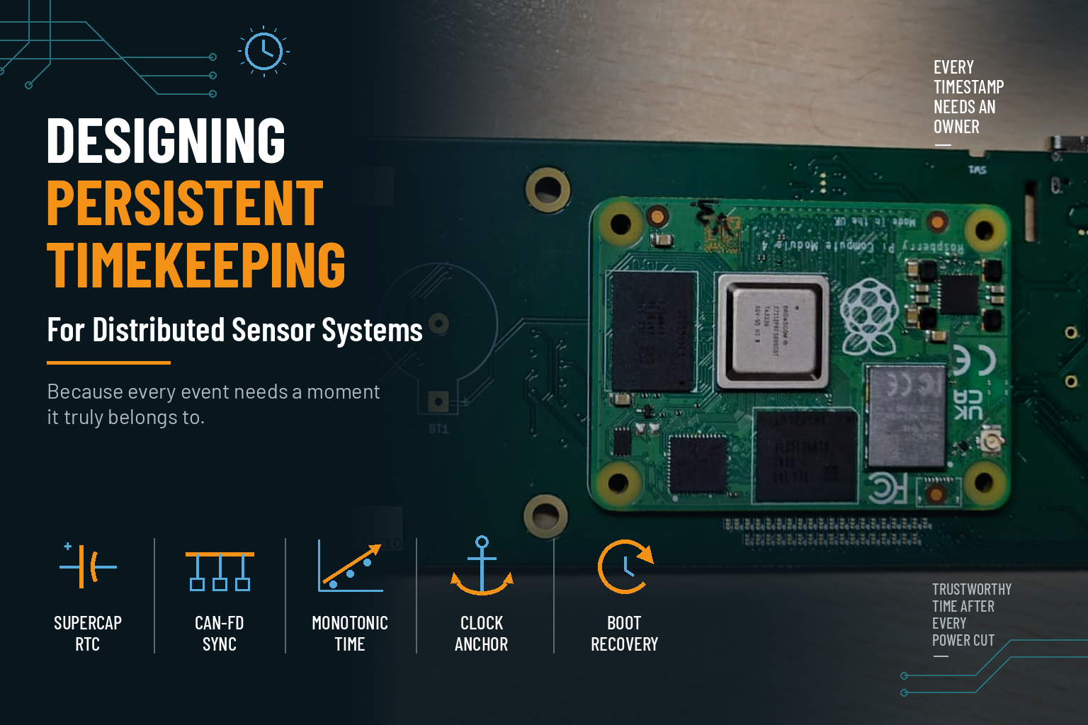
Designing Persistent Timekeeping for Distributed Sensor Systems
Introduction
In early bring-up, time looks like a solved problem.
The SoC has an RTC. A 32.768 kHz crystal is fitted on the low-frequency oscillator. The board boots, the network connects, NTP sets the clock, and every log line carries a sensible date.
Then the product is unplugged.
Power returns. The processor boots with no idea what time it is. The sensor modules start sending data before WiFi has associated. The first cloud connection fails certificate validation because the clock reads 1970. Events captured in that first minute have no reliable place on the timeline.
In a feeding monitor built from a main processor module and three sensor modules on a CAN-FD bus, that is not a cosmetic problem. One module weighs two bowls and reads the collar RFID tag, one captures images, one records audio. A feeding event only means something when all three agree on when it happened.
At Hoomanely, time is not treated as a service the operating system provides once the network is up. It is treated as a hardware requirement: it needs an owner, a persistent source, a distribution path, and a defined behaviour when it cannot be trusted.
The question is not:
"Does the processor have an RTC?"
The real engineering question is:
"Will every timestamp be correct, or honestly marked as uncertain, in the first second after power comes back?"
Designing timekeeping is about answering that question before the product reaches customers.
An oscillator on the schematic is not a timekeeper
The main processor on this product is a TI AM62A7. It has an RTC peripheral in its wake-up domain, and our module fits a 32.768 kHz tuning-fork crystal on the low-frequency oscillator pins. On the schematic review checklist, "RTC: present, crystal fitted" gets a tick.
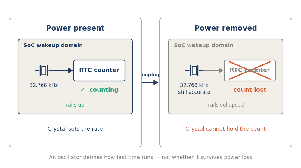
The detail that matters is not on the schematic. On this SoC family the RTC has no persistent voltage domain. It keeps time through Deep Sleep, because the wake-up domain stays powered, but it does not retain its value across a main-domain reset or a power cycle. There is no VBAT pin to back it up.
The crystal defines how fast the counter runs. It does nothing to keep the counter powered. When the rails collapse, the oscillator stops, and an accurate crystal is accurate about nothing.
The common mistake is treating "has an RTC" as a yes/no feature rather than asking three separate questions:
- Persistence: does the count survive every way the product loses power, including an unplug?
- Accuracy: how far does it drift over temperature and years, not just at 25 °C?
- Availability: is it valid before the first piece of data needs a timestamp?
On accuracy alone the on-module crystal was also weak. A ±20 ppm tuning-fork part drifts about 10 minutes a year at room temperature. Its parabolic tempco adds roughly another 30 ppm at 55 °C, a normal internal ambient for a sealed appliance next to a processor running inference.
The product impact is larger than a wrong date on a dashboard. With the clock at epoch, the first TLS handshake after an outage fails, because every server certificate looks "not yet valid". The device needs the network to learn the time and needs the time to trust the network.
One owner of time, and two kinds of time
The first decision was ownership. Four processors each keeping their own calendar time is four clocks to set, four to drift, and four sources of disagreement. So only the main module keeps wall-clock time. The three sensor modules keep none.
Each sensor module runs a free-running local tick counter. The main module broadcasts a SYNC frame once a second on the lowest CAN identifier on the bus. Each sensor module captures its local tick at SYNC reception using the CAN peripheral's hardware receive timestamp, and fits a simple offset-and-skew mapping over the last sixteen syncs.
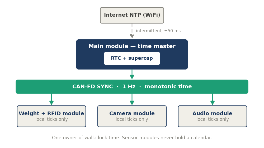
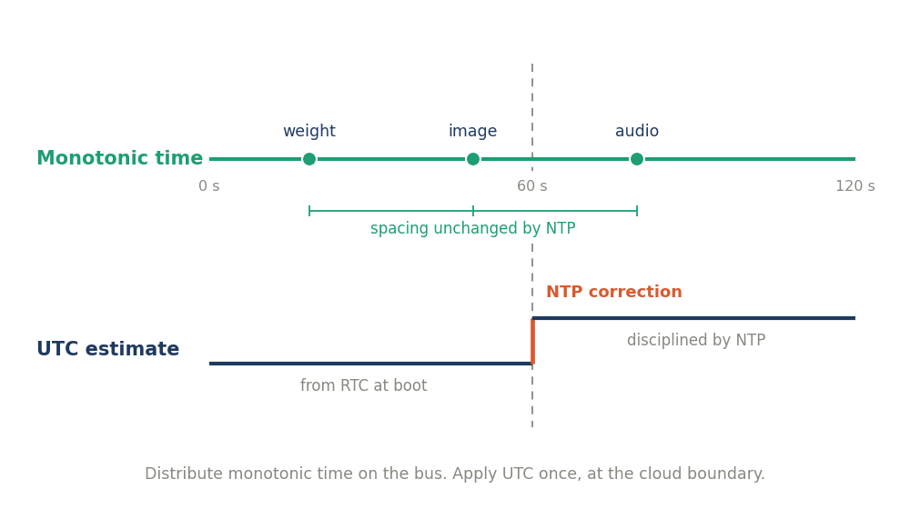
The second decision was which time to distribute. SYNC carries the main module's monotonic time, not UTC. This is the decision that makes everything else robust.
NTP over a consumer WiFi dongle arrives 30–90 seconds after boot and may correct UTC by hundreds of milliseconds. If the sensor modules were aligned to UTC, that correction would shear every cross-module correlation in the buffer. Aligned to monotonic time, their relative alignment never moves. UTC becomes a mapping applied once, at the cloud boundary.
The third decision was where the persistent clock lives. We chose an external I²C RTC with its own backup element, placed on the main module rather than the carrier board:
Criterion | RTC on carrier | RTC on main module |
|---|---|---|
Connector pins used | I²C already exported | None |
Alarm to a wakeup-domain GPIO | Needs a spare connector pin | Direct, on-module |
Module boots with valid time on any carrier | No | Yes |
Space for a large backup element | Plenty | Limited |
Thermal environment | Cooler | Hottest board in the product |
The trade-off is honest: on-module placement limits the backup element's size and puts it on the warmest board. We accepted that because the module becomes self-sufficient. A time master that cannot keep time across a power cycle is an incomplete module.
A nanoamp circuit on a noisy board
The product is a plug-in appliance, so we did not want a coin cell. A soldered, non-serviceable lithium cell brings button-cell safety regulation, lithium transport paperwork, and an end-of-life date nobody can predict. A supercapacitor has none of those, and every reconnection recharges it.
We selected an RTC with an integrated calibrated crystal, internal backup switchover and an internal trickle charger. The integrated crystal matters more than the ±1 ppm figure. It removes an oscillator layout problem from a module that already has tight constraints around its own crystal.
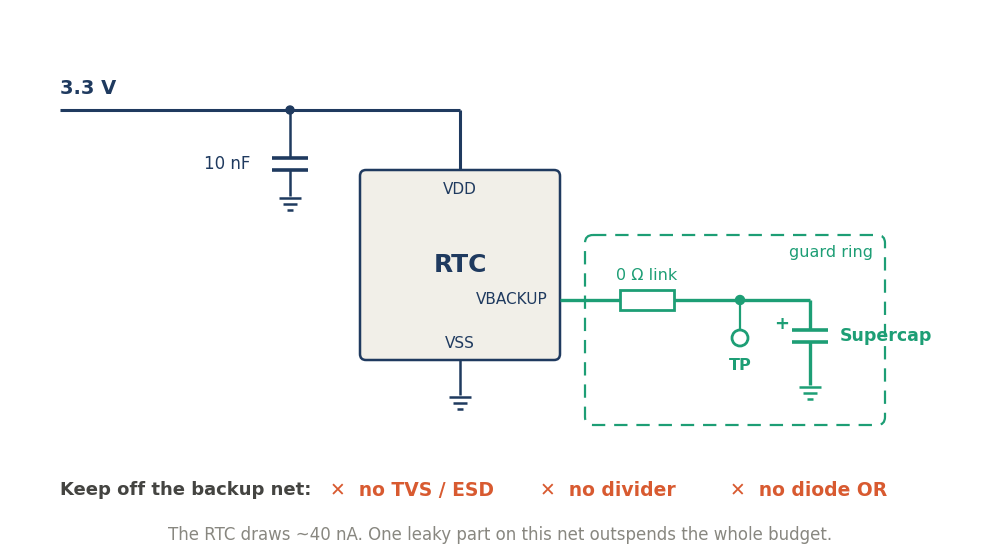
The circuit is deliberately almost nothing:
- RTC supply from the 3.3 V rail, with a 10 nF decoupler within 2 mm.
- The backup pin to the supercapacitor through a 0 Ω link and a test point.
- The unused event input tied to ground, because it must not float.
- The trickle charger's internal resistor, at least 2 kΩ, limits charge current.
That last point is not about charge time. A discharged supercapacitor is a short circuit. Charged from a low-impedance source, it pulls the rail down at power-on, the PMIC's power-good never asserts, and the board boot-loops. It looks exactly like a sequencing fault.
The real design work is what is kept off the backup net. The RTC draws about 40 nA. A single TVS diode leaks around 1 µA; a 10 MΩ monitoring divider draws 300 nA. Either one alone outspends the whole budget, so the net carries no ESD part, no divider, and no diode OR-ing.
Layout and manufacturing follow from the same number. The cluster sits away from the SoC and regulators, because EDLC leakage roughly doubles every 10 °C. A ground guard ring surrounds the backup node. The assembly note specifies a clean process, because flux residue across 3 V at these currents is a real conduction path.
The backup element has one electrical rule that is also a safety rule: never exceed its rated voltage. Common single-cell EDLCs are rated 3.0 V, while a 3.3 V rail at +5 % is 3.47 V. We closed that with a 3.3 V-rated part, trading holdup from about a week to about a day. For an appliance that is normally plugged in, a day covers moves and outages; the recovery path covers the rest.
Designing for the day the clock is wrong
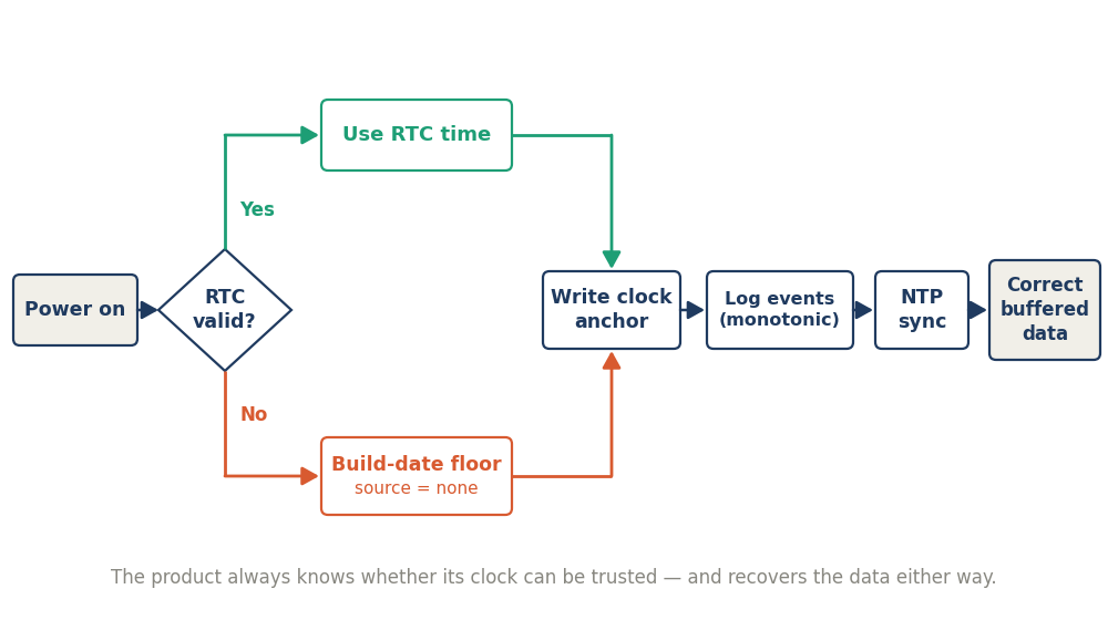
A backup element buys time; it does not guarantee it. The product will eventually boot with no valid clock: after a long unplug, after months on a warehouse shelf, or with a degraded capacitor years into service. The question is whether it knows.
The RTC sets a power-fail flag when its supply drops below its operating threshold. Firmware reads it at every boot. If set, the clock source is reported as "none" instead of letting a plausible-looking wrong time into the record. On this product that is a normal path, not a fault, so it is not logged as an error.
Every record carries two times: monotonic time since boot, and the best UTC estimate at the moment it was written. The first record of every boot, and every later clock step, is a clock anchor tying one to the other. When NTP finally arrives, data captured before it is corrected in the cloud with a single offset. Without the anchor, that data is permanently unplaceable.
The TLS deadlock gets a small, deliberate fix. If the RTC is invalid, the system clock is set to the firmware build date before any connection is attempted. Every certificate issued before that build validates, and NTP corrects the clock seconds later.
The event flow exposed one more degraded mode. A dog arriving at the bowl is detected by the weight and RFID module, which alerts the main module, which commands image and audio capture. With Linux in that loop under inference load, alert-to-command latency varies from about 1 to 50 ms, before camera start-up. The dog's arrival can fall in the gap. So audio and camera keep short pre-trigger ring buffers, and the first frames recorded are from before the trigger.
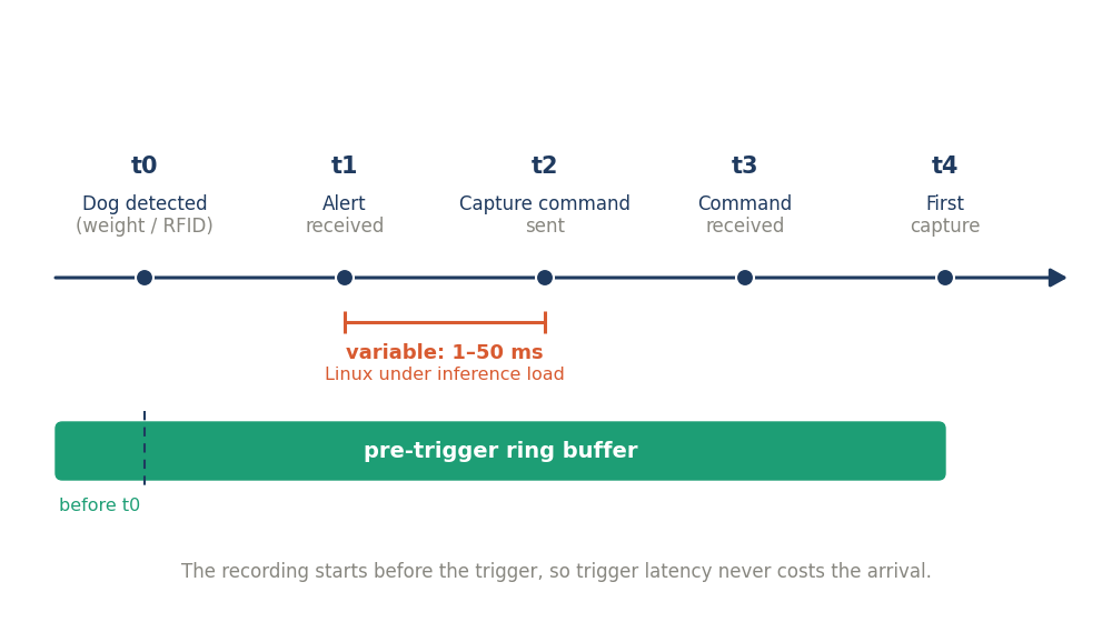
Debugging gets easier as a side effect. Each event logs detection, alert receipt, command send and first capture, all on the master timebase. That is a per-event latency histogram for free, across the whole fleet. Field reports of "the video starts too late" become a query, not an investigation.
Hoomanely Design Perspective
We treat time the way we treat power: as something the hardware architecture owns, with a single source, defined boundaries and a known failure behaviour. The expensive time bugs are rarely in the RTC. They sit in the seams: which module is authoritative, which timebase crosses the bus, what the first second after power-on looks like.
Drawing those boundaries early made the rest cheap. Sensor firmware got simpler because it never handles a calendar. Cloud logic got simpler because every record says how much it can be trusted. The hardware change itself was four small parts and a guard ring.
The design goal was not a clock that is never wrong. It was a system that is never silently wrong. A timestamp marked "none" is useful data; a confident, precise, incorrect one poisons everything joined to it.
Conclusion
A crystal on the schematic answers "how fast", not "since when". In a distributed product, the question worth asking in the first design review is which module owns time, and what that module does in the first minute after the power comes back.