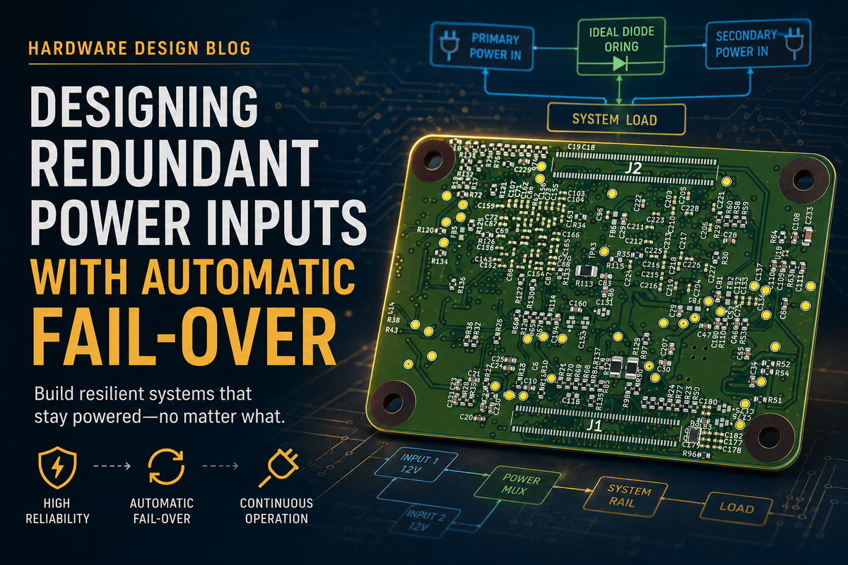
Designing Redundant Power Inputs With Automatic Failover
A redundant power input is one of those features that looks finished the moment the second connector lands on the board. Two sources, one rail, a pair of diodes. It powers up. It passes review.
Then a unit in the field runs for four months on its backup pack because nobody noticed the adapter had quietly stopped working — and the first anyone hears about it is when the backup runs out too.
At Hoomanely, our devices sit in homes and run continuously. They sense, they stream, and they occasionally move. They are fed from a wall adapter and they must keep running when that adapter is unplugged, browns out, or is switched off at the socket by someone tidying up. On that kind of product, redundancy isn't a bullet on a datasheet. It is the thing that decides whether the device is trustworthy.
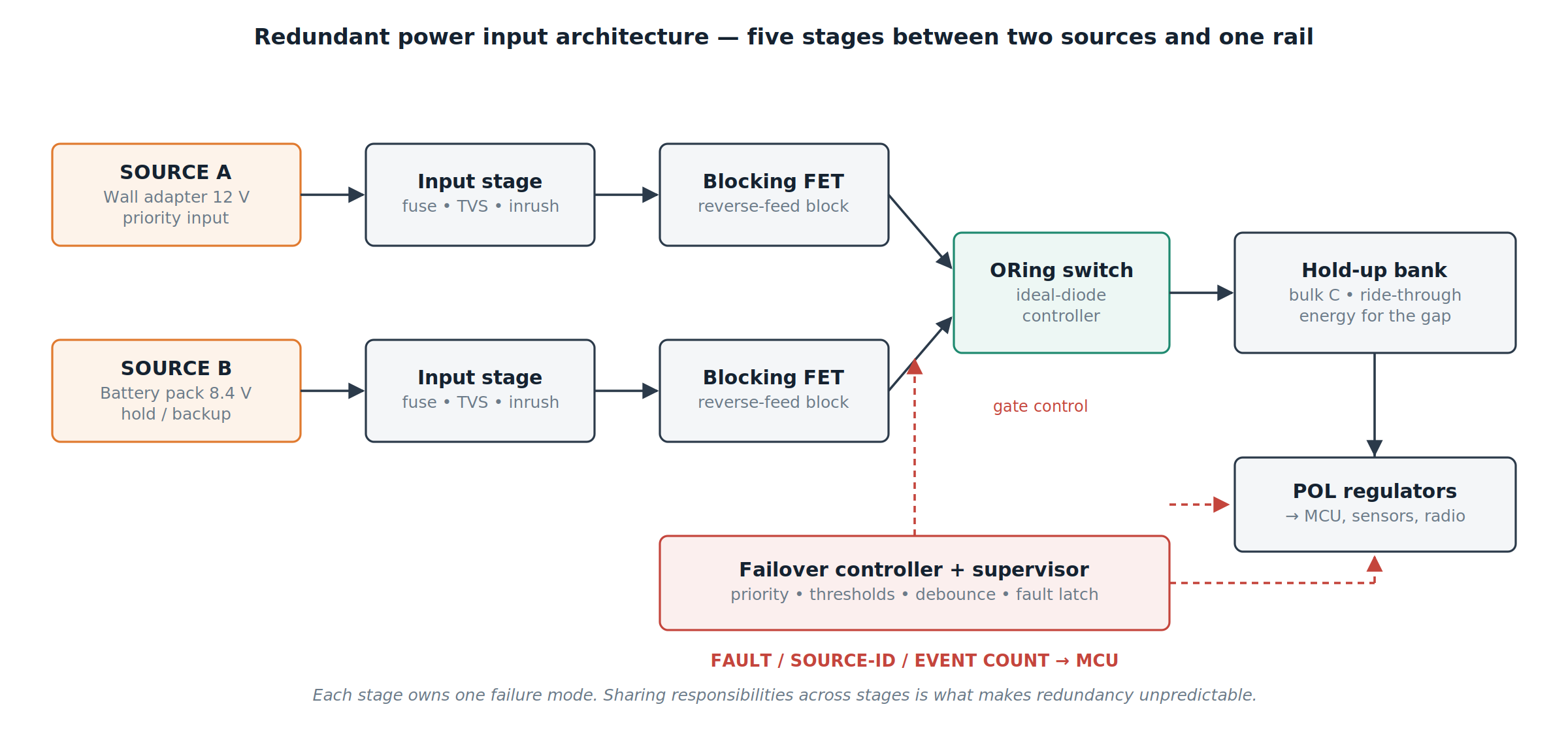
So we stopped treating a redundant input as a wiring choice. We treat it as a small control system: five stages, four failure modes, and one window you either measure or don't have.
The hidden problem: a diode-OR that never actually fails over
The conventional dual-input design is a Schottky OR. Two sources, two diodes, one node. It is cheap, and it does technically work.
But look at what it commits you to. Both sources conduct whenever their voltages are close, so the backup pack slowly drains while the adapter is plugged in. At 3 A, the forward drop burns well over a watt as heat nobody budgeted for. The rail sits permanently below the lower source minus that drop, eating headroom before the point-of-load regulators even start. Handoff happens because the diodes stop conducting, not because anything decided it should.
And firmware never finds out. A source was lost, the product kept running, and nothing was recorded.
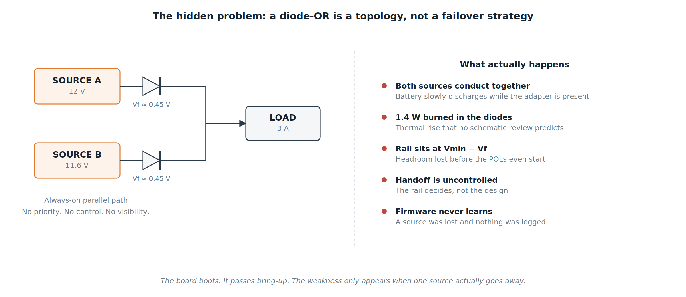
The board boots. It survives bring-up. The weakness only appears when a source actually goes away — usually in a customer's home, months later.
Dual-input switching: pick the topology for what it guarantees
We evaluate dual-input switching by what it promises under fault, not by part count.
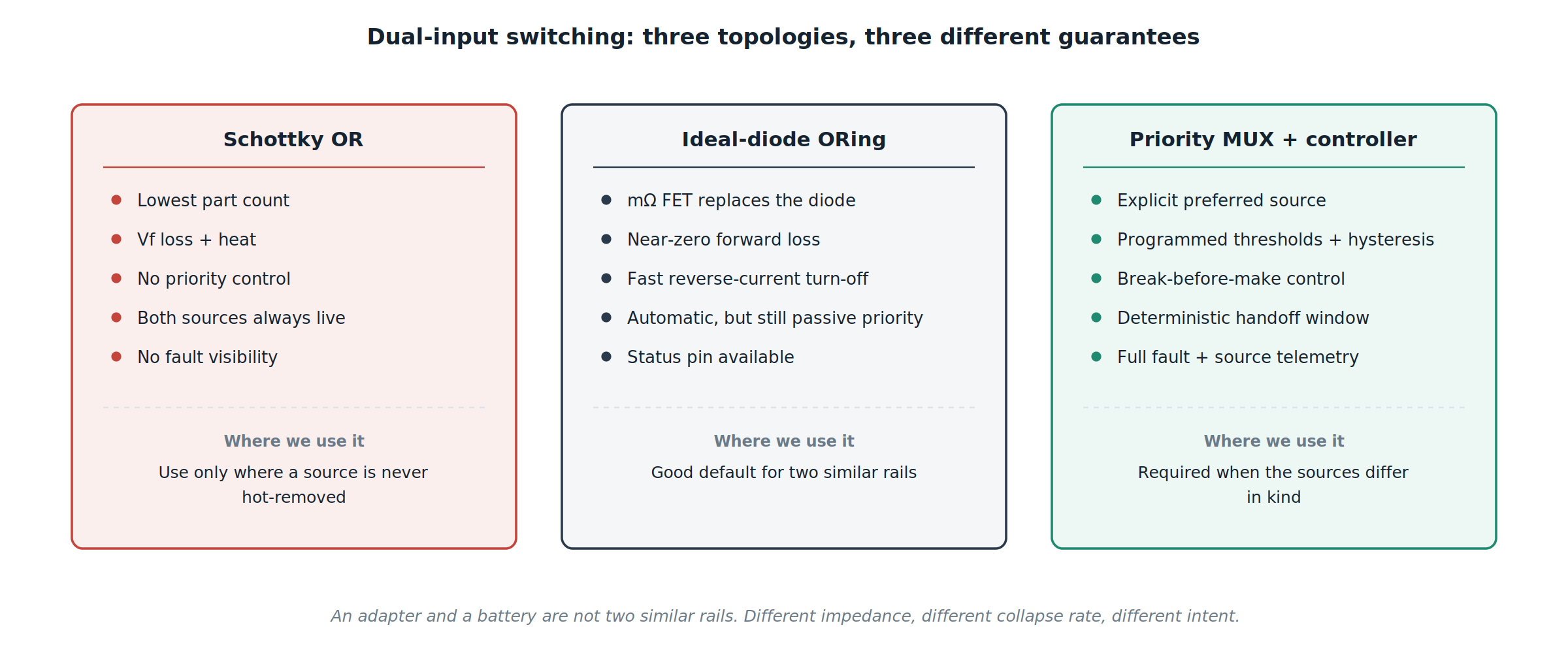
A Schottky OR promises nothing except that current will find a path. Ideal-diode ORing replaces the diode with a milliohm FET and a controller that watches drain-to-source voltage, which removes the loss and the heat and adds fast reverse turn-off — but priority is still whichever source happens to be higher.
A priority MUX with a supervisor is different in kind. You declare which source is preferred. You set the threshold and the hysteresis at which it is abandoned. You control whether the transition is break-before-make. The handoff stops being an emergent property of two voltages and becomes a designed event.
That distinction matters most when the two sources aren't alike. An adapter and a battery have different impedance, different collapse behaviour, and completely different intent. The adapter is the source you want. The battery is the source you tolerate. A topology that can't express that preference cannot implement it.
Reverse-feed prevention: the body diode decides what the circuit really does
The most common redundancy bug we see is a single series FET used as a blocking switch. The gate is driven low, the designer considers the path off, and the schematic agrees.
The silicon does not. Every power MOSFET has a body diode, and in one polarity it conducts regardless of the gate.
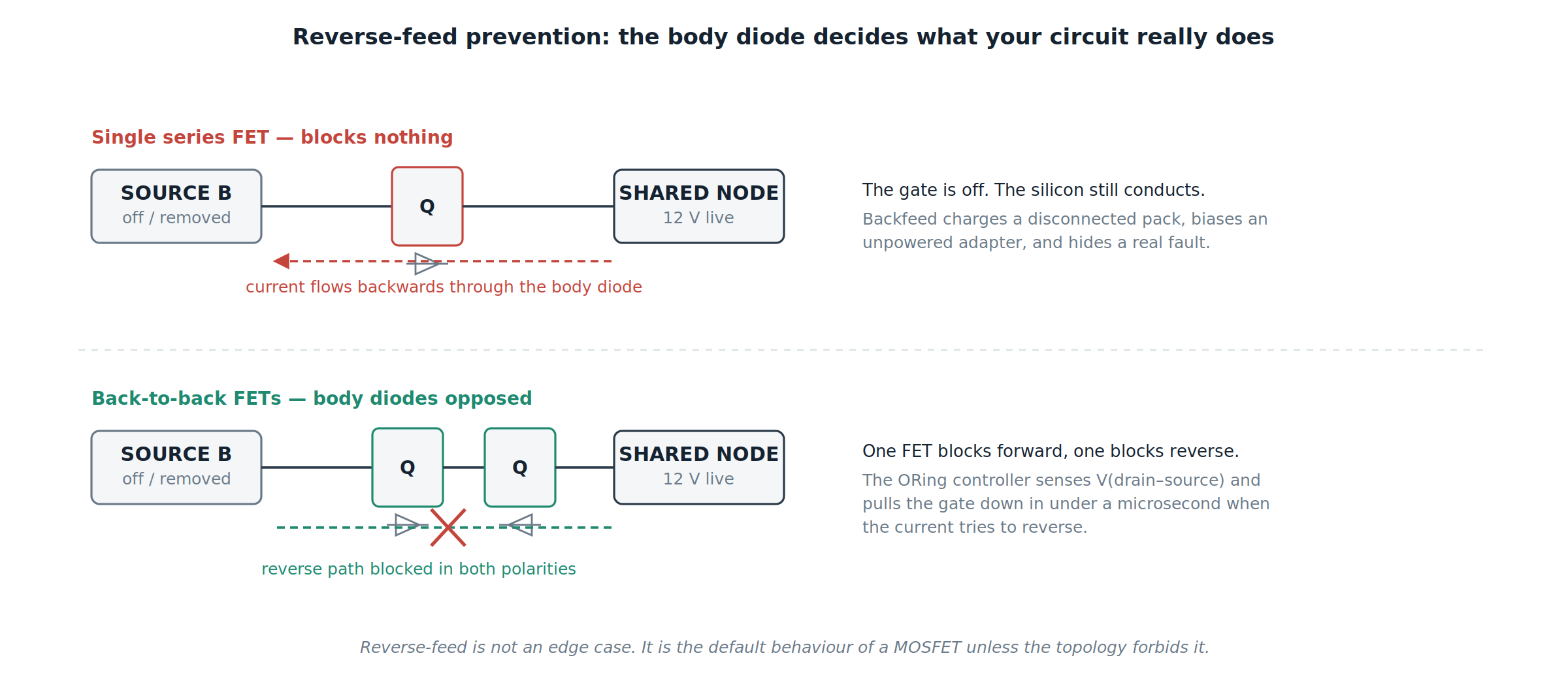
The consequences are specific. A disconnected battery gets charged from the live rail through a path nobody drew. An unpowered adapter is biased backwards through its own output stage. Worst of all, the fault is masked: the shared node stays up, the supervisor sees a valid source, and a genuine failure reports as healthy.
Our rule is that any input capable of being back-driven gets back-to-back FETs with opposed body diodes, controlled by an ORing controller that senses reverse current and pulls the gate down in well under a microsecond. Reverse-feed isn't an edge case to be handled. It is the default behaviour of a MOSFET unless the topology forbids it.
Seamless source handoff: design the window, don't hope for it
"Seamless" is the word that hides the engineering. Nothing about a failover is instantaneous. There is a real interval between the moment one source stops delivering and the moment the other is fully in control, and during that interval the rail is supported by capacitance alone.
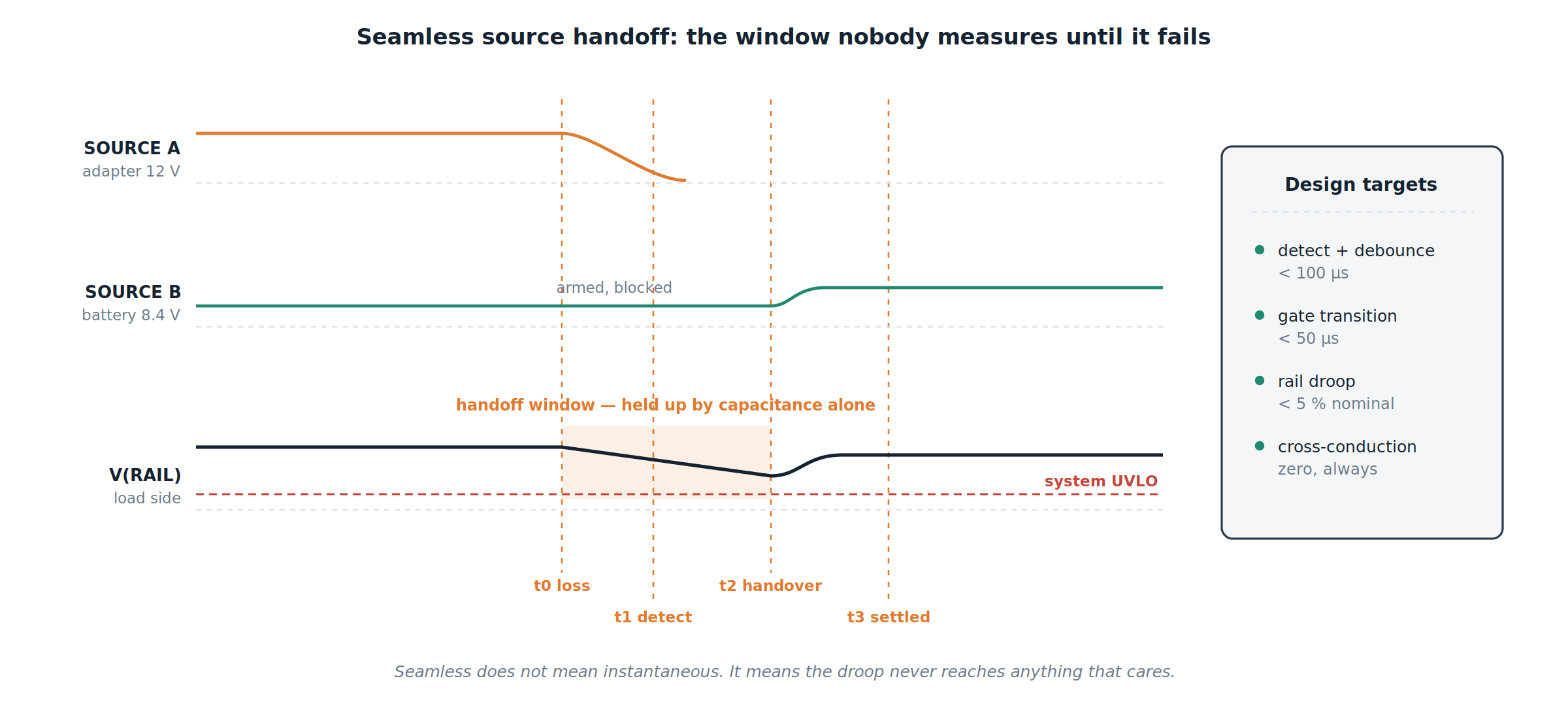
We break that interval into named parts and put a number on each: detection and debounce, gate transition, and regulator settling. Debounce matters more than it sounds — an adapter that flickers during a brownout should not cause four failovers in a millisecond. The comparator needs hysteresis, and the decision needs a short qualifying time.
Our targets are detection and debounce under 100 µs, gate transition under 50 µs, and total rail droop within 5% of nominal. Cross-conduction between sources is not a target, it is a prohibition — two sources briefly connected in parallel is a battery charging an adapter through a path with no current limit.
Seamless does not mean instantaneous. It means the droop never reaches anything that cares.
Rail hold-up: the energy budget that covers the gap
Once the handoff window has a number, hold-up stops being guesswork. The capacitance you need follows directly from the energy the load consumes during the window and the voltage you're allowed to lose.
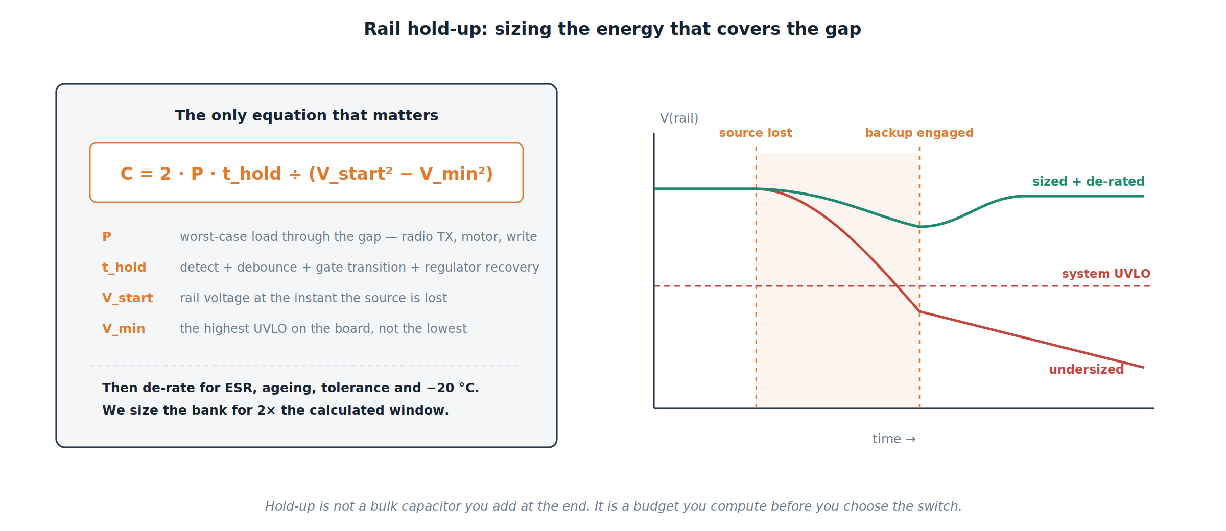
Three things go wrong here in practice. Engineers use average load current instead of the worst case, when the gap may well coincide with a radio transmission, a motor start, or a flash write. They use the lowest UVLO on the board instead of the highest, forgetting that the first regulator to drop out defines the failure. And they size at room temperature with nominal ESR, ignoring that a cold electrolytic at −20 °C delivers a fraction of the energy the datasheet implies.
We compute the requirement, apply the de-rating, and then size the bank for twice the calculated window. Hold-up is not a bulk capacitor you add at the end of layout. It is a budget you compute before you choose the switch.
Failover fault signaling: never fail over silently
This is the section most redundant designs skip entirely, and it is the one that turns redundancy from a feature into a system.
A failover that nobody records is a single point of failure that has already been used up. The device is now running with no margin, reporting perfect health, and waiting for the second source to fail.
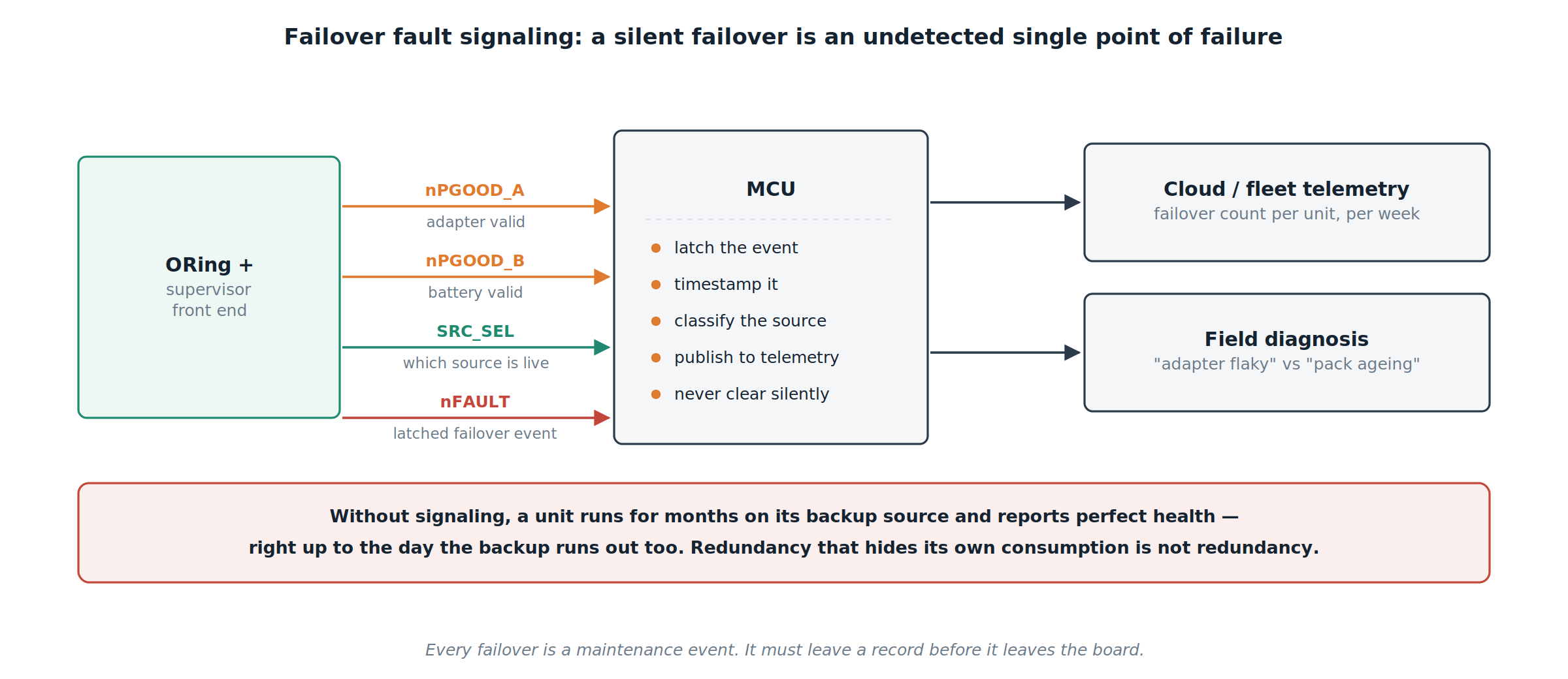
So our front end exposes state, not just power. Each input has its own validity signal. A select line reports which source is actually carrying the load. A separate fault line latches the failover event itself, so a transition that lasted 80 µs cannot be missed by firmware that was busy.
The MCU's job is to latch, timestamp, classify, and publish. Across a fleet, that turns into something operationally valuable: a failover count per unit, per week. Two events a month on one unit is a flaky adapter. A rising count across a batch is a pack ageing. Neither is visible if the hardware fails over silently.
Validation: the failover you didn't measure is the failover you don't have
A redundant input cannot be signed off in schematic review. Every claim in this article is a claim about transient behaviour, and transient behaviour has to be captured on a scope.
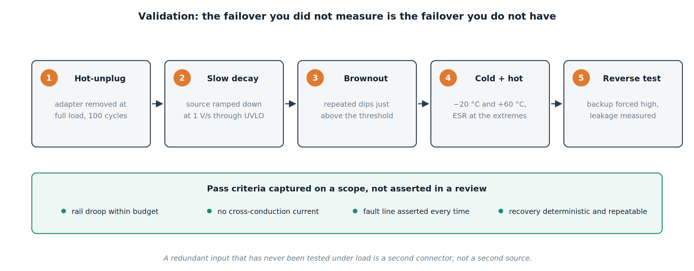
We test hot removal at full load over many cycles, slow decay through the threshold at around 1 V/s, repeated brownouts that hover just above the trip point, and the whole sequence at both temperature extremes. We also force the backup high with the primary present and measure the leakage that comes back.
The pass criteria are numeric: droop within budget, no measurable cross-conduction, the fault line asserted on every single event, and recovery that is deterministic and repeatable. An input that has never been tested under load is a second connector, not a second source.
Conventional redundancy vs structured redundancy
The conventional approach adds two diodes, assumes the higher source wins, sizes the bulk capacitor by habit, and lets firmware discover problems later. The Hoomanely approach declares a preferred source, gates each input with a blocking element that cannot be back-driven, budgets the handoff window in microseconds, sizes hold-up from that window with de-rating, latches every failover as a reportable event, and proves all of it on a scope before release.
The parts differ a little. The intent differs completely.
What we observed after restructuring
- Backup packs stopped discharging while the adapter was connected, which extended usable pack life considerably
- Input-stage dissipation dropped enough to remove a thermal hot spot near the connector
- Brownout events stopped producing MCU resets, because the rail no longer dipped below the highest UVLO on the board
- Field failures became diagnosable, since every unit reports which source it is running on and how often it has switched
- Bring-up got faster, because failover behaviour was already characterised rather than discovered
The core principle
Exactly one source should be carrying the load at any instant, the system should always know which one, and the transition between them should be short enough that nothing downstream notices.
Everything else follows from that sentence: priority, reverse blocking, hold-up sizing, fault signaling.
Final thought
Redundant power is invisible when it works. There is no screen for it, no setting, no feature to demo. It shows up only as a device that stays on through a brownout, a firmware update that survives an unplugged adapter, and a support ticket that never gets filed.
Adding a second source is easy. Designing the moment between them is the actual work. And that moment — measured in microseconds, on a scope, before anything ships — is the difference between a product with a backup and a product that genuinely doesn't go down.