
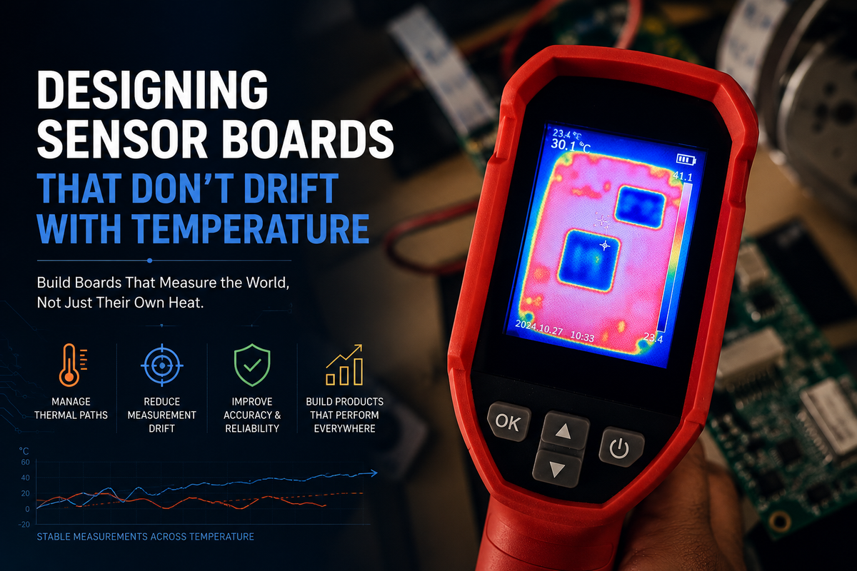
Designing Sensor Boards That Don't Drift With Temperature
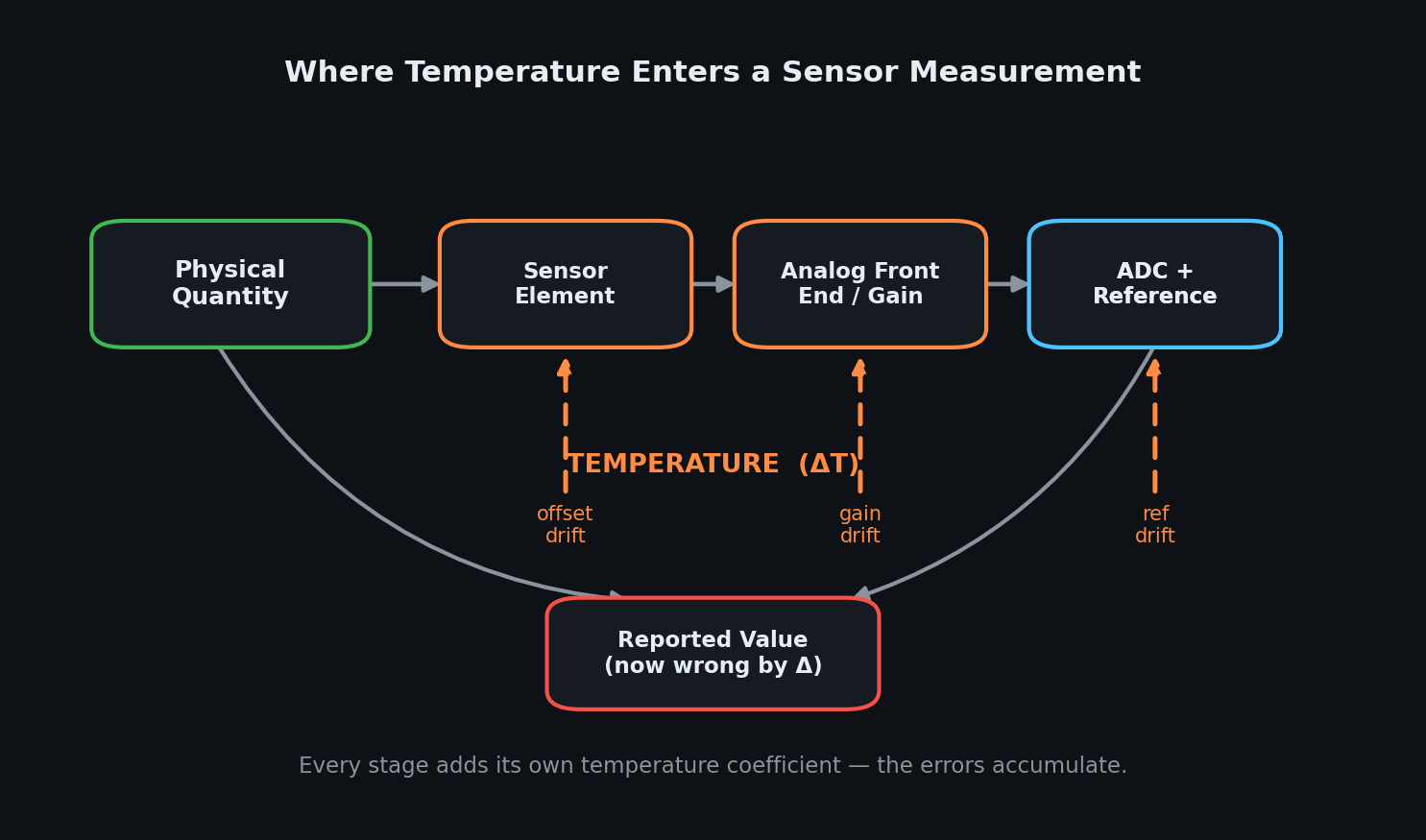
A sensor board that's accurate at 25°C on a clean bench isn't a finished product. It's a starting point. The moment that board ships inside a real device, it stops living at 25°C. It sits next to a regulator that warms under load. It's carried outdoors in winter and left in a hot enclosure in summer. It self-heats every time a radio transmits or a nearby motor spins.
And quietly, across all of that, the numbers it reports begin to move. Not because the thing being measured changed. Because the board's own temperature did.
This is drift. At Hoomanely, where sensor data feeds decisions about a living animal's wellbeing, drift is not a cosmetic spec-sheet footnote. A reading that wanders a few percent across the operating range can turn a healthy baseline into a false alarm, or hide a real one.
The mistake most teams make is treating drift as a single problem with a single fix, pick a better part, add a calibration point, move on. In reality, temperature enters a measurement at several independent stages, each with its own behavior. Designing a board that holds steady means understanding every one of those entry points and assigning clear ownership for each. Because once a measurement passes through multiple temperature-sensitive stages, "stable" is no longer a property of one component. It becomes a property of the whole architecture.
Drift is not one thing
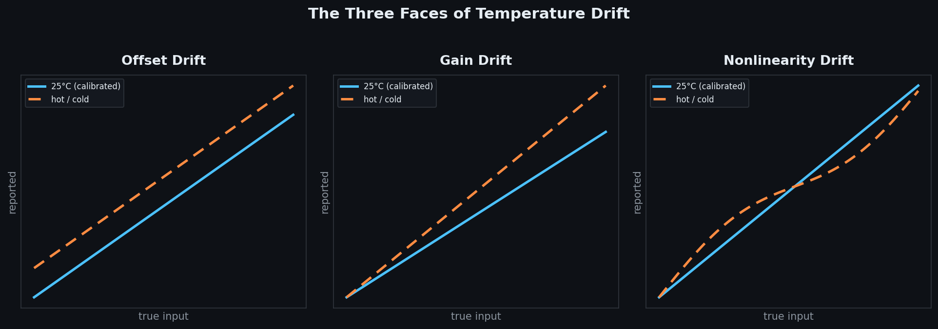
When engineers say a sensor "drifts," they usually mean one of three very different failures. Conflating them is how compensation strategies go wrong.
The first is offset drift, where the whole transfer curve shifts up or down, and a zero reading is no longer zero. The second is gain drift, where the slope of the curve changes, so the error grows with the size of the signal, small readings look fine while large readings are badly off. The third, and the nastiest, is nonlinearity drift, where the curve bends in a way that changes shape with temperature, so no single offset or scale factor can undo it.
These three behave differently and demand different remedies. Offset drift can often be canceled with a periodic re-zero. Gain drift needs a ratiometric reference or a two-point correction. Nonlinearity drift can only be tamed by characterizing the part across temperature and storing a real model. This distinction matters because a board can pass a single calibration at room temperature and still fail across its range, the dominant error was nonlinear all along. You cannot fix what you have not separated.
Self-heating breaks the datasheet's promises
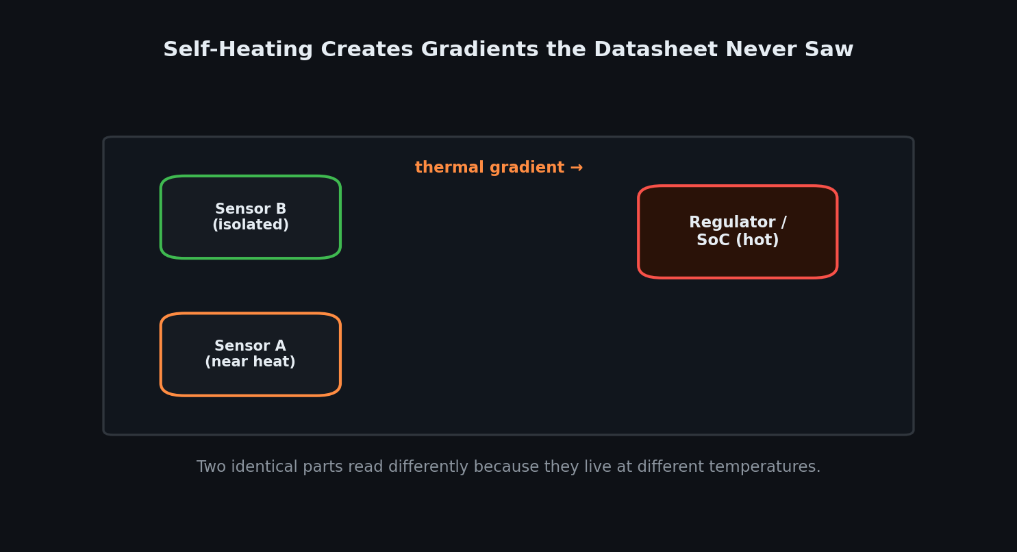
Datasheets quote temperature coefficients under an unspoken assumption: that the sensor and its surroundings sit at one uniform, settled temperature. Real boards almost never do.
Put a switching regulator, a processor, or a power amplifier on the same board as a sensitive analogue front end, and you've placed a heat source millimeters from the thing you're trying to measure precisely. The result is a thermal gradient across the board. Two identical sensors can read differently simply because one lives closer to the warm corner than the other.
Worse, self-heating is dynamic. The board is cooler right after power-up and warmer after the radio has been transmitting for a minute. So the drift isn't a fixed bias you can calibrate out once, it tracks the device's own activity. A reading that depends on whether the WiFi was recently busy is exactly the kind of bug that survives bench testing and only appears in the field. This is why thermal behavior has to be treated as a layout and architecture concern, not just a component-selection one. The part's temperature coefficient is only half the story. The other half is what temperature the part actually experiences.
A drifting reference corrupts everything downstream
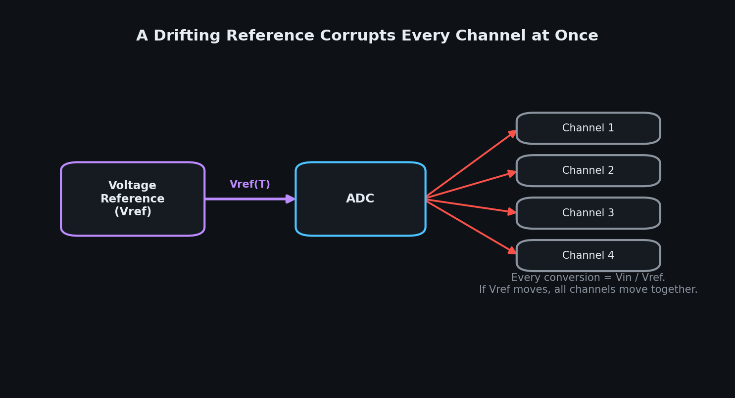
Of all the drift sources on a sensor board, the voltage reference punishes you the most for ignoring it, because it sits underneath every single measurement. An ADC doesn't measure volts, it measures a ratio between the input and its reference. Every conversion is effectively Vin divided by Vref. So if the reference moves with temperature, every channel and every reading moves with it, in lockstep, regardless of how good the sensors themselves are.
This is deceptive during debugging. When channels drift independently, you suspect the sensors. When all channels drift together by the same proportion, the reference is almost always the culprit, but only if you think to look there. Teams routinely spend days chasing individual sensor coefficients while the shared reference quietly scales the entire system.
The architectural lesson is that the reference deserves a deliberate decision, not a default. A cheap reference with a 50 ppm/°C coefficient can dominate the entire error budget of an otherwise excellent design. And where measurements only need to be ratiometric, comparing a sensor to the same reference that drives it, the reference's absolute drift can be made to cancel out entirely. Choosing whether your measurement is absolute or ratiometric is one of the highest-leverage drift decisions on the board.
You cannot compensate what you cannot see
The first step in keeping a board steady isn't correcting temperature error, it's knowing the temperature in the first place, at the place that matters. A single temperature sensor in the corner of the board tells you very little if the gradient across the board is several degrees. The temperature you need is the temperature at the sense element and its reference, not the ambient temperature of the enclosure.
This is why a well-designed sensor board places its own temperature sensing physically close to the components whose drift it intends to correct. Once you can measure local temperature reliably, drift stops being random, it becomes a function. And functions can be inverted.
Compensation turns drift into a known quantity
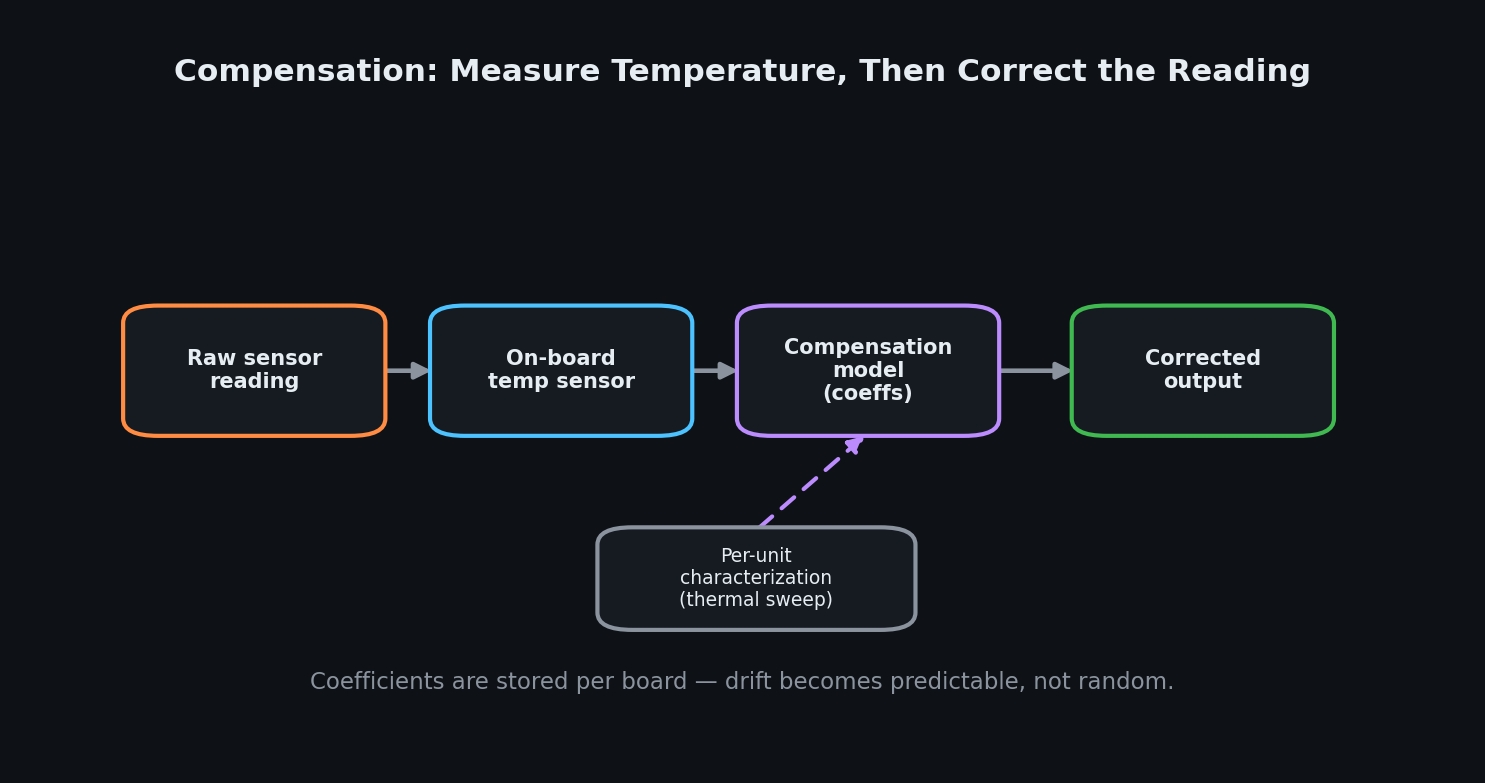
With local temperature in hand, the board can correct itself. The pipeline is straightforward in principle:
- The raw sensor reading comes in
- A co-located temperature sensor reports the conditions
- A compensation model
- Built from coefficients measured for that specific board during a thermal sweep
- Applies the correction
- What leaves the board is a corrected value
- Not a raw count
The part that separates a robust product from a fragile one is where those coefficients come from. Coefficients copied from a datasheet describe a typical part, not your part. The real gains come from characterizing each unit, or each batch depending on cost targets, across the actual operating range and storing per-unit corrections. This is more work at the factory, but it converts an unpredictable, part-to-part variation into a deterministic, repeatable correction. The goal isn't to eliminate the physics of drift, that's impossible. The goal is to make drift predictable, so it can be subtracted away with confidence.
Layout is the first line of defence
Compensation can only correct the drift it can model. The cheapest drift to deal with is the drift that never reaches the sensor in the first place, and that's won or lost at layout.
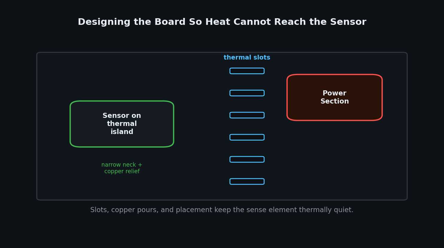
Good thermal layout treats the sense element as something to be protected. Placing it away from heat sources is the obvious move. Less obvious, but equally important, are the techniques that interrupt the path heat takes:
- Thermal relief slots cut into the board to break conduction
- Narrow copper necks that isolate a sensor island from the warm bulk of the board
- Careful copper pour management so a hot plane doesn't act as a heat-spreader straight into the analog section
There's also a stability dimension. A sensor mounted on a large copper pour will track the board's slow thermal changes smoothly. One on an isolated pad with poor thermal mass can respond to fast transients and add noise. The right answer depends on whether you're fighting gradients or transients, which is again why drift has to be reasoned about per board rather than by rule of thumb. Layout will never make a board perfectly isothermal, but every degree of gradient it removes is a degree the compensation model no longer has to chase.
The Hoomanely approach: vBus
Everything above describes how to make a single sensor board hold steady. Hoomanely products aren't single boards, they're systems of sensing subsystems, and that changes the problem.
When several sensor boards feed a common host, the naive architecture has every board ship raw counts up to a central processor, which then tries to compensate all of them using shared reference and shared assumptions. This is exactly the design that fails with temperature, since each board lives at a different temperature, sees a different gradient, and would need its own reference and its own model, none of which a central compensator can see.
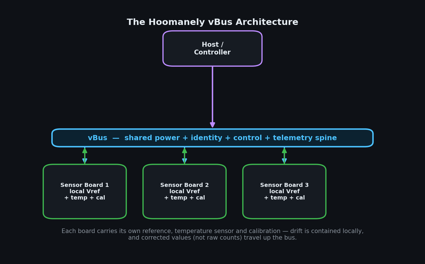
Our answer is vBus, the architecture we use to connect sensing and control subsystems across a product. The core principle of vBus is simple:
- Drift is contained and corrected locally
- At the board that owns it
- Only corrected values travel up the bus
Each sensor board on the vBus is self-sufficient with respect to accuracy, carrying its own voltage reference so its measurements never depend on a reference sitting at a different temperature elsewhere in the system, its own local temperature sensing placed next to the elements it protects, and its own calibration coefficients characterized for that physical board.
vBus is more than a power rail, it's a shared spine for power, identity, control, and telemetry. Every board announces what it is, reports its own health, and delivers data the host can trust without re-deriving it. Because each board owns its error budget, the host is freed from an impossible job, it never has to guess the temperature of a board it cannot feel. This has a compounding benefit: when a board's drift behavior is owned and corrected at the source, the rest of the system becomes simpler and more deterministic. A new sensor board can be added to the vBus without forcing the host to learn a new compensation model, because the board arrives already telling the truth.
Validation means sweeping the range, not checking a point
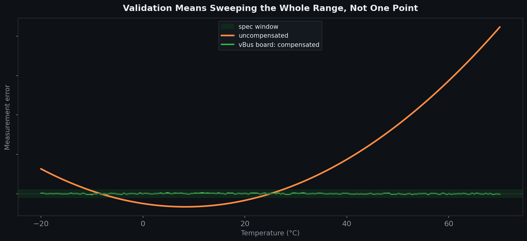
A drift specification proven at room temperature isn't proven at all. The only honest way to validate temperature stability is to take the board across its full operating range in a thermal chamber and watch the error the entire way. An uncompensated board traces out a curve, often a gentle parabola, that wanders far outside the spec window at the extremes even while passing comfortably at 25°C.
A properly compensated vBus board, with local reference, local temperature, and per-unit coefficients, stays flat inside the window across the whole sweep. Validation also has to include the dynamics: soak the board at temperature and confirm it settles, cycle it up and down and confirm there's no hysteresis, exercise self-heating by running the rest of the system at full activity and confirm the sensor holds. A board that only passes when the chamber moves slowly is hiding a transient it will meet in the field. Steady-state accuracy at one temperature tells you almost nothing. Surviving the full sweep, repeatedly, in both directions, is what earns the claim.
Drift stability is an ownership contract
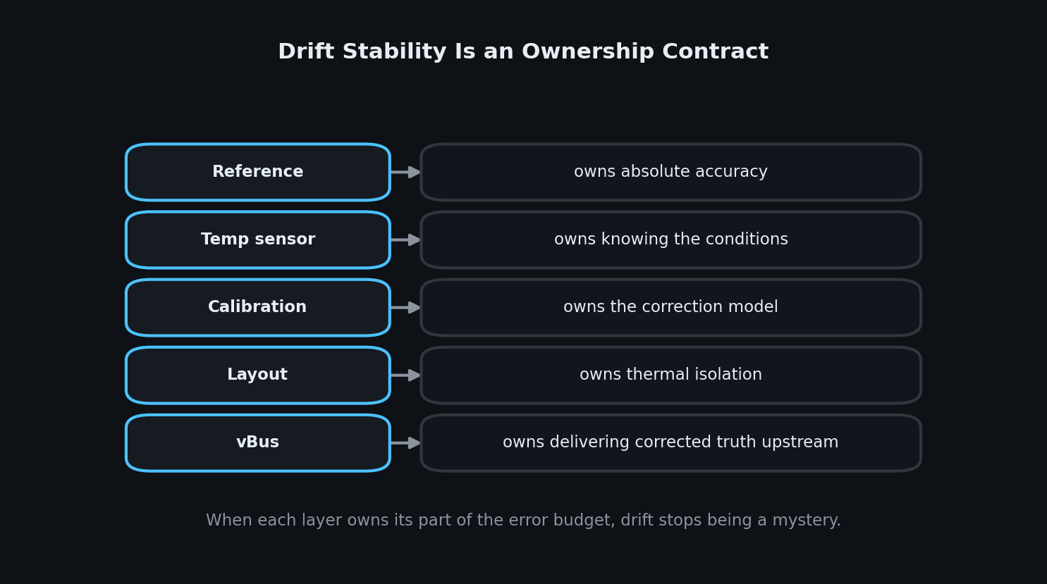
Step back from the individual techniques and a pattern emerges. Every method above is really about assigning responsibility for one slice of the error budget to the part of the system best placed to own it. The reference owns absolute accuracy. The local temperature sensor owns knowing the conditions. The calibration model owns the correction. The layout owns thermal isolation. And vBus owns delivering corrected, trustworthy values upstream so nothing else has to reconstruct them.
When those boundaries are explicit, drift stops being a mystery that surfaces in the field, it becomes an engineered, bounded quantity. When they're blurred, a shared reference at the wrong temperature, a host trying to compensate boards it cannot feel, a calibration that assumed a typical part, drift becomes the kind of intermittent, temperature-dependent bug that's almost impossible to reproduce on a bench.
Final thoughts
It's tempting to think of temperature stability as a component-selection problem. Buy a low-drift sensor, buy a low-drift reference, and the board will be stable. The parts matter, but they aren't the architecture.
A sensor board that doesn't drift with temperature is one where every entry point for thermal error has been identified, where local temperature is actually measured at the point it matters, where drift is characterized into a model rather than hoped away, where the layout keeps heat at arm's length, and where, in a multi-board system, each board is made responsible for its own truth before it speaks on the bus. At Hoomanely, that last principle is why vBus exists. We don't ask a central processor to understand the thermal life of every sensor in the product, we design each board to understand its own, and to report values that are already correct. Drift doesn't disappear, physics doesn't allow that. But it stops being a system-wide unknown and becomes a contained, owned, validated quantity. And a measurement you can trust across the whole temperature range is the only kind worth building a product on.



