Designing Status LEDs That Speak: The Silent Language of Smart Products

When a user picks up your IoT device, they ask three immediate questions without saying a word:
"Is it on?"
"Is it working correctly?"
"How much battery is left?"
At Hoomanely, we answer all three questions through a single, intelligent interface: RGB LEDs driven by PWM signals. Not as decoration, not as an afterthought, but as a carefully designed communication system that builds user trust and reduces support calls.
This isn't about making products look pretty with blinking lights. It's about creating a visual language that users intuitively understand, that provides actionable information, and that enhances the product experience without requiring a manual.
Let me share how we've systematically designed status indication LEDs that truly communicate.
Why RGB LEDs on PWM? The Technical Foundation
Before diving into the communication strategy, let's establish the technical approach we use at Hoomanely.
The RGB LED Advantage
Traditional status indication uses multiple discrete LEDs—one for power, one for connectivity, one for errors, maybe one for battery. This approach has limitations:
❌ PCB space consumption: Each LED needs its own footprint, current-limiting resistor, and GPIO pin
❌ Limited information density: Each LED conveys only on/off state or simple blink patterns
❌ Poor scalability: Adding new status indicators requires hardware changes
❌ User confusion: Multiple LEDs create visual clutter—which LED means what?
RGB LEDs solve all of these problems elegantly:
• Single physical component can display millions of color combinations
• PWM control enables precise brightness and color mixing
• Rich information encoding through color, brightness, and patterns
• Software-defined behavior allows updates and customization
• Minimal PCB footprint compared to multiple discrete LEDs
PWM: The Control Mechanism That Makes It Work
At Hoomanely, we drive RGB LEDs using PWM (Pulse Width Modulation) signals from MCUs or MPUs, depending on the product complexity.
How PWM controls RGB LEDs:
Each color channel (Red, Green, Blue) connects to a PWM-capable GPIO pin. By varying the duty cycle from 0-100%, we control the perceived brightness of each color:
- 0% duty cycle: LED channel off (appears black)
- 50% duty cycle: Half brightness
- 100% duty cycle: Full brightness
Color mixing through PWM:
By independently controlling R, G, and B channels, we create any color:
- Red (100%, 0%, 0%): Pure red
- Green (0%, 100%, 0%): Pure green
- Blue (0%, 0%, 100%): Pure blue
- Yellow (100%, 100%, 0%): Red + Green
- Cyan (0%, 100%, 100%): Green + Blue
- Magenta (100%, 0%, 100%): Red + Blue
- White (100%, 100%, 100%): All channels full
- Orange (100%, 50%, 0%): Full red + half green
This gives us a rich palette to encode different system states uniquely and memorably.
MCU vs MPU: Choosing the Right Controller
For simpler products (sensor nodes, basic IoT devices):
We use MCU-based PWM (e.g., STM32, ESP32):
- Built-in hardware PWM peripherals
- Typically 8-16 bit resolution (256-65536 brightness levels)
- Low CPU overhead (hardware generates PWM automatically)
- Perfect for battery-powered devices (low power consumption)
For complex products (gateways, edge processors):
We use MPU-based PWM (e.g. Raspberry Pi compute modules):
- Software PWM or dedicated PWM controllers
- Integration with complex state machines and decision logic
- Ability to drive multiple RGB LEDs independently
- Rich animation and pattern capabilities
Implementation example from our sensor hub:
Hardware: STM32L476 MCU with three hardware PWM channels
RGB LED: Common-cathode SMD LED (Red: GPIO PA8, Green: PA9, Blue: PA10)
PWM frequency: 1kHz (above human flicker perception, below audible range)
Resolution: 8-bit (256 levels per channel, sufficient for smooth gradients)
Current limiting: 1kΩ resistor per channel (approximately 2-3mA per color at 3.3V)
This configuration provides smooth, flicker-free color transitions while consuming minimal power (6-9mA worst case, all channels full brightness).
The Visual Language: Battery Status Communication
Battery status is the most critical information users need. At Hoomanely, we've developed a comprehensive battery indication system that provides accurate information at a glance.
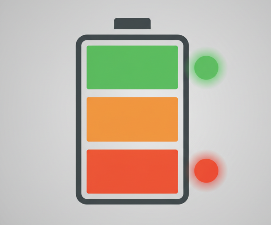
The Color Coding Strategy
We use a traffic light metaphor that users universally understand:
Green Zone (80-100% charge):
- Solid green: Fully operational, excellent battery life remaining
- Message to user: "Everything is great, use normally"
- PWM values: R:0%, G:100%, B:0%
Yellow/Amber Zone (50-79% charge):
- Solid yellow: Good battery, but awareness recommended
- Message to user: "Still healthy, but plan for charging soon"
- PWM values: R:100%, G:70%, B:0% (warm amber, not harsh yellow)
Orange Zone (20-49% charge):
- Solid orange: Battery getting low, charging recommended
- Message to user: "Time to think about charging"
- PWM values: R:100%, G:30%, B:0%
Red Zone (5-19% charge):
- Pulsing red: Low battery, charge soon
- Message to user: "Charge immediately to avoid shutdown"
- Pattern: Smooth breathing effect (fade in/out over 2 seconds)
- PWM values: R:100%, G:0%, B:0%, modulated by sine wave
Critical Zone (<5% charge):
- Fast blinking red: Imminent shutdown
- Message to user: "Device shutting down very soon"
- Pattern: 0.5s on, 0.5s off (urgent attention-grabbing)
Charging Status Integration
When the device is charging, we overlay charging information:
Charging in progress:
- Slow pulsing of current battery color: Indicates charging active
- Pattern: Fade from dim to bright over 1.5 seconds, repeat
- Example: If battery at 60%, pulsing amber indicates "charging, currently 60%"
Fully charged:
- Solid green + brief white flash every 10 seconds: Indicates charging complete but still connected to power
- Message to user: "Fully charged, safe to disconnect or leave connected"
Charging fault:
- Alternating red/orange: Indicates charging problem (temperature out of range, battery fault, etc.)
- Pattern: 1s red, 1s orange, repeat until fault clears
This comprehensive battery language means users never need to guess about power status—they can see device health instantly from across the room.
The Technical Implementation Challenge
Getting smooth battery indication requires careful firmware design. Here's our approach at Hoomanely:
Battery voltage sampling:
- Sample battery voltage every 30 seconds during normal operation
- Average over 5 samples to smooth out transient voltage drops
- Map voltage to percentage using calibrated discharge curve (not linear!)
Hysteresis for zone transitions:
- Implement 5% hysteresis when transitioning between zones
- Prevents rapid flickering between colors at zone boundaries
- Example: Transition from orange to yellow at 50%, but don't transition back to orange until 45%
PWM frequency optimization:
- Use 1-2kHz PWM frequency (above flicker perception, below audible whine)
- Higher frequencies increase CPU/power consumption unnecessarily
- Lower frequencies cause visible flicker
Gamma correction:
- Human perception of brightness is non-linear
- Apply gamma correction (γ ≈ 2.2) to PWM duty cycles for perceptually linear brightness
- Makes fade animations appear smooth and natural
Example firmware structure:
void update_battery_led(uint8_t battery_percent) {
    static uint8_t last_zone = 0;
    uint8_t current_zone;

    // Determine zone with hysteresis
    if (battery_percent >= 80) current_zone = ZONE_GREEN;
    else if (battery_percent >= 50) current_zone = ZONE_YELLOW;
    else if (battery_percent >= 20) current_zone = ZONE_ORANGE;
    else if (battery_percent >= 5) current_zone = ZONE_RED;
    else current_zone = ZONE_CRITICAL;

    // Apply hysteresis (only change zone if crossed threshold by 5%)
    if (abs(current_zone - last_zone) > 1 && !hysteresis_check()) return;

    // Update LED with appropriate color and pattern
    set_led_color_pattern(current_zone);
    last_zone = current_zone;
}
This approach creates reliable, accurate battery indication that users learn to trust.
Fault Indication: Communicating Problems Clearly
When something goes wrong, users need to know immediately—and ideally, what specifically went wrong. At Hoomanely, we've developed a fault indication system that provides specific, actionable information.
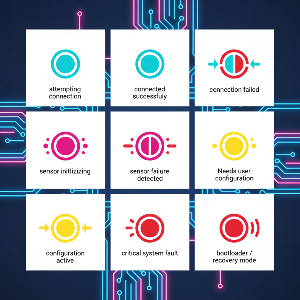
Fault Categories and Visual Encoding
Connectivity Faults (Network/Communication Issues):
- Blinking cyan: Attempting to connect
- Solid cyan: Connected successfully
- Fast blinking red/cyan: Connection failed, retrying
- Message to user: Clear distinction between "trying," "connected," and "failed"
Sensor Faults (Hardware/Data Issues):
- Blinking magenta: Sensor initialization or calibration
- Alternating red/magenta: Sensor failure detected
- Pattern: 1s red, 1s magenta (distinctive from charging faults)
- Message to user: "Hardware problem, not user error"
Configuration Faults (User Action Required):
- Blinking yellow: Waiting for user configuration
- Alternating yellow/white: Configuration mode active
- Message to user: "Device needs setup, please use app/interface"
Firmware/System Faults (Critical Errors):
- Rapid blinking red (3Hz): Watchdog reset, memory fault, critical exception
- Solid red + periodic white flash: Bootloader/recovery mode
- Message to user: "Serious problem, contact support or attempt recovery"
The Diagnostic Advantage
By using unique color combinations and patterns for different fault types, we enable:
Remote troubleshooting: User can describe LED behavior over phone/email, support can identify problem immediately
Reduced support load: Common issues (connectivity, low battery) are self-explanatory, users don't need to contact support
Faster resolution: Specific fault indication guides users to correct solution (charge battery vs. check network vs. reset device)
Implementation: Fault Priority System
Multiple faults can occur simultaneously. We implement a priority system at Hoomanely:
Priority 1 (Highest): Critical system faults (displayed immediately, override everything)
Priority 2: Battery critical (<5%)
Priority 3: Sensor/hardware faults
Priority 4: Connectivity issues
Priority 5 (Lowest): Normal status indication
Fault transition logic:
If multiple faults active, display highest priority fault. When that fault clears, immediately transition to next highest priority indication.
Time-slicing for multiple faults:
For faults of similar priority, we use time-slicing:
- Display fault A for 2 seconds
- Display fault B for 2 seconds
- Repeat
This allows users to see that multiple issues exist without creating confusing overlapping patterns.
Building User Trust Through Consistency
The most important aspect of status LED design isn't technical—it's psychological. Users must learn to trust that the LED accurately represents system state.

The Trust-Building Principles We Follow at Hoomanely
Principle 1: Consistency Across Products
All Hoomanely products use the same visual language:
- Green always means "healthy/good"
- Red always means "problem/low/critical"
- Yellow/Amber always means "caution/attention"
- Cyan always means "connectivity/communication"
- Magenta always means "sensor/peripheral"
Users who own multiple Hoomanely products don't need to re-learn LED meanings—the language is universal across our product line.
Principle 2: Accurate Representation (No False Positives)
We rigorously validate that LED indications match actual system state:
- Battery LED shows true battery capacity, not optimistic estimates
- Connectivity LED only shows "connected" after successful data exchange
- Fault indications only appear for confirmed faults, not transient glitches
Example: In our sensor nodes, we don't show "connected" immediately after WiFi association. We wait for successful data transmission to cloud server. This prevents users from seeing "connected" status when the device is associated to WiFi but has no internet access.
Principle 3: Predictable Behavior (No Surprises)
LED behavior must be deterministic and repeatable:
- Same system state always produces same LED indication
- Transitions between states are smooth and logical
- No random or unexplained LED changes
Principle 4: Documentation and Education
We provide clear documentation (user manual, quick-start guide, in-app help) explaining:
- What each color means
- What each pattern means
- What action users should take for each indication
But critically, we design the LED language to be intuitive enough that most users don't need documentation—they figure it out through universal color associations (green=good, red=bad).
Advanced Techniques: Animation and Attention Management
Beyond static colors and simple blinking, we use PWM-controlled animations to convey richer information and manage user attention effectively.
Implementation:
Brightness varies sinusoidally over 2-3 seconds
Creates gentle "breathing" effect that's noticeable but not alarming
Used for: Normal operation indicators, charging status, idle states
Mathematical approach:
brightness = (sin(2π × time / period) + 1) / 2
PWM_duty = base_brightness × brightness × gamma_correction
This creates smooth, organic-feeling animations that are pleasant to watch and don't demand attention.

Fast Blinking (High-Priority, Urgent Information)
For critical alerts requiring immediate user action:
Implementation:
Sharp on/off transitions at 2-4Hz
High contrast (full brightness to off)
Used for: Critical battery, urgent faults, user action required
Fast blinking leverages the human attention system—peripheral vision is highly sensitive to motion/flicker, ensuring users notice even when not looking directly at the device.
Color Transitions (Status Changes)
When transitioning between states, we use smooth color morphing rather than abrupt changes:
Implementation:
Interpolate R, G, B values independently over 0.5 seconds
Creates smooth color transition that feels natural
Used for: Battery zone changes, fault resolution, connectivity state changes
This prevents jarring color changes that might confuse users about whether the device malfunctioned or simply changed state.
Idle State Strategy
When device is in normal operation with no issues, we face a design choice: should the LED be on or off?
Our philosophy at Hoomanely:
Battery-powered portable devices: LED off or very dim during idle to conserve power. Brief status pulse every 30 seconds shows device is operational.
Mains-powered stationary devices: Dim green breathing pattern during idle. Provides reassurance that device is operating without being distracting.
Critical infrastructure devices: Always-on status indication with brightness adjusted for environment (brighter in bright ambient light, dimmer in dark rooms).
Power Consumption Considerations
RGB LEDs, especially at full brightness, consume significant power. On battery-powered devices, this matters critically.
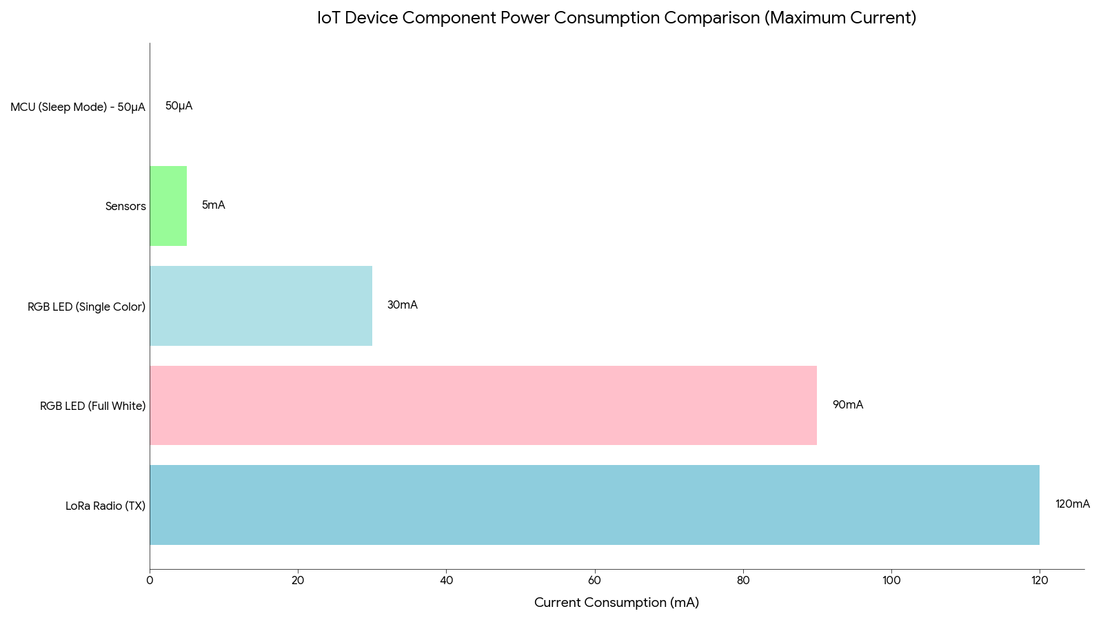
Power Budget Analysis
Typical RGB LED power consumption:
- Single color (R, G, or B) at full brightness: 20-30mA at 3.3V (66-100mW)
- All three colors (white) at full brightness: 60-90mA at 3.3V (200-300mW)
- At 50% brightness: Proportionally reduced (due to PWM)
For context in an IoT sensor node:
- MCU sleep current: 10-50µA (0.03-0.16mW)
- LoRa radio transmit: 120mA peak (400mW)
- Sensor operation: 1-5mA average (3-16mW)
An RGB LED at full white brightness consumes more power continuously than the MCU in sleep mode consumes in days!
Our Power Optimization Strategy at Hoomanely
Brightness scaling based on battery level:
- 80-100% battery: Full brightness (100%)
- 50-79% battery: Reduced brightness (60%)
- 20-49% battery: Low brightness (30%)
- <20% battery: Minimal brightness (10%) except during critical warnings
This provides clear status indication while conserving battery when it matters most.
Automatic dimming in stable states:
When device has been in stable state (e.g., connected, good battery) for >2 minutes, LED dims to 20% brightness. Any state change restores full brightness briefly.
Ambient light sensing (advanced products):
On some Hoomanely products, we include an ambient light sensor that adjusts LED brightness:
- Bright environment: Increase LED brightness for visibility
- Dark environment: Reduce LED brightness to avoid being obnoxious (especially at night)
This not only saves power but also improves user experience—nobody wants a bright green LED shining in their bedroom at 2 AM.
The Complete Design Checklist
When implementing status LEDs at Hoomanely, we follow this systematic checklist:
Hardware Design
✅ RGB LED selection: Common-cathode or common-anode based on GPIO sink/source capability
✅ Current limiting: Appropriate resistor values for 2-5mA per channel at 50% brightness
✅ PWM-capable GPIOs: Verify MCU/MPU has sufficient hardware PWM channels
✅ PCB placement: LED visible in final enclosure, positioned for user line-of-sight
✅ Light pipe design: If LED is internal, ensure light pipe provides clear, uniform illumination
Firmware Design
✅ Color palette definition: Document all colors and their meanings
✅ Pattern library: Create reusable animation functions (blink, breathe, fade, etc.)
✅ Priority system: Implement fault priority and time-slicing logic
✅ Hysteresis: Prevent rapid state transitions that cause flickering
✅ Gamma correction: Apply for perceptually linear brightness
✅ Power optimization: Brightness scaling based on battery level
User Experience
✅ Intuitive color mapping: Green=good, red=bad, yellow=caution
✅ Distinctive patterns: Each system state has unique, recognizable pattern
✅ Documentation: Clear explanation of all LED indications
✅ Accessibility: Consider color-blind users (patterns in addition to colors)
✅ Night mode: Option to disable or dim LEDs during specified hours
Validation Testing
✅ Visibility testing: LED clearly visible from all normal viewing angles
✅ Battery life impact: Measure power consumption across all LED states
✅ Accuracy validation: LED indication matches actual system state
✅ User testing: Non-technical users correctly interpret LED meanings
✅ Longevity testing: 1000+ hours of operation, verify no degradation or color shift
The Result: Products That Communicate
At Hoomanely, our systematic approach to status LED design has transformed how users interact with our products.
Users no longer ask:
- "Is it on?"
- "Is the battery dead?"
- "Is it connected?"
- "Is something wrong?"
Instead, they say:
- "I can see it's healthy and connected—green LED"
- "Battery is getting low—it's showing orange"
- "It's trying to connect—cyan is blinking"
- "Something's wrong with the sensor—it's showing that red/magenta pattern"
The humble RGB LED, controlled through simple PWM signals, has become one of the most important user interfaces in our products.
Beyond user clarity, this also dramatically improves our ability to diagnose issues remotely.
Because every LED color and animation pattern corresponds to a precise internal system state, our support team can identify what’s happening inside a device just from the user describing the LED behavior — no logs, no debugging session, no guesswork. When a customer says, “It’s alternating red and magenta,” we instantly know a sensor module isn't initializing. “Fast red/cyan blink” tells us there’s a connection failure and we can guide them directly to a network check instead of general troubleshooting. This turns abstract technical problems into simple, actionable conversations and reduces resolution time from hours to minutes.
Final Thoughts
Designing effective status LEDs isn't about adding colorful lights to make products look high-tech. It's about creating a visual language that:
- Communicates accurately and honestly
- Builds user trust through consistency
- Provides actionable information at a glance
- Reduces confusion and support burden
- Enables remote troubleshooting
- Enhances the overall product experience
At Hoomanely, we treat status LED design as seriously as we treat circuit design, firmware architecture, and mechanical engineering. Because ultimately, the best technology is invisible—but when it needs to speak, it should speak clearly.


