DMA-Friendly Buffers: Mastering High-Speed Camera Capture
Building a production-ready camera system with 45 MB/s sustained throughput
Direct Memory Access (DMA) promises zero-CPU data transfers, but poor buffer design can turn that promise into corrupted frames, system crashes, and unpredictable behavior.
This post shares hard-won lessons from building Hoomanely's camera module—a dual-sensor system that captures and processes visual and thermal data in real-time on an STM32 microcontroller running at 250 MHz. We'll explore the critical design decisions around buffer alignment, cache coherence, and interrupt handling that enable reliable and sustained throughput with minimal CPU intervention.
By the end, you'll understand not just what to do, but why these techniques work and how to apply them to your own high-performance embedded systems.
The naive approach—letting the CPU copy this data byte-by-byte—would consume 100% of our processing budget, leaving nothing for actual application logic. DMA seems like the perfect solution: configure it once, let hardware handle the transfers, and the CPU is free to do useful work.
But here's what we learned the hard way: DMA without proper buffer design is worse than no DMA at all.
Initial symptoms included:
- Random pixel corruption in captured images
- Occasional system freezes during high-throughput periods
- DMA transfers taking 50% longer than theoretical maximum
- Mysterious "ghost pixels" from previous frames bleeding through
The root causes? Misaligned buffers, cache coherence violations, and interrupt handlers blocking for milliseconds. Here's how we solved each problem.
Understanding STM32 Memory Architecture
Before diving into solutions, let's map the battlefield. The STM32 provides several distinct memory regions, each with different characteristics that matter for DMA:

/* Memory regions from our linker script */
MEMORY {
    DTCM  (xrw) : ORIGIN = 0x20000000, LENGTH = 128K   /* Fastest, no cache */
    SRAM1 (xrw) : ORIGIN = 0x20020000, LENGTH = 256K   /* Fast, cached */
    SRAM2 (xrw) : ORIGIN = 0x20060000, LENGTH = 256K   /* Fast, cached */
    SRAM3 (xrw) : ORIGIN = 0x200A0000, LENGTH = 128K   /* Fast, cached */
    PSRAM (xrw) : ORIGIN = 0x60000000, LENGTH = 8M     /* External, no cache */
}
The critical insight: DMA controllers bypass CPU caches entirely. When DMA writes to SRAM1/2/3, the CPU's data cache may still contain old data. When the CPU reads that location, it gets stale cache data instead of the fresh DMA transfer. This is the root of most DMA data corruption bugs.
Our solution uses PSRAM for large DMA buffers because:
- It's uncached—no coherence issues
- It's huge (8 MB vs 640 KB internal)
- It's fast enough for our throughput needs (400 MB/s theoretical)
For the camera frame buffer, this was a simple decision:
/* From dcmi_camera.c - 517KB frame buffer in internal SRAM */
uint32_t dcmi_frame_buffer1[BUFFER_SIZE / 4]
    __attribute__((aligned(32)));  /* 32-byte alignment critical for DMA */
Buffer Alignment: The 32-Byte Rule
Here's the fundamental issue: ARM Cortex-M33 processors use 32-byte cache lines. If your DMA buffer isn't aligned to 32 bytes, cache operations must work with partial cache lines—reading, modifying, and writing back more data than necessary. This causes:
- Performance penalty: 3-4 bus cycles instead of 1 for burst transfers
- Cache thrashing: Neighboring data gets evicted unnecessarily
- Subtle corruption: Adjacent variables get overwritten if they share a cache line
Calculating Buffer Size with Alignment
Our sensor configuration requires careful calculation:
#define IMAGE_WIDTH  640
#define IMAGE_HEIGHT 400
#define EMBEDDED_ROWS 4   // 2 for data + 2 for statistics
#define TOTAL_HEIGHT (IMAGE_HEIGHT + EMBEDDED_ROWS)  // 404 lines

/* Each pixel is 12 bits, packed into 16-bit words */
#define BUFFER_SIZE (IMAGE_WIDTH * TOTAL_HEIGHT * 2)
// = 640 × 404 × 2 = 517,120 bytes
Why the embedded rows? The outputs metadata in the first 4 rows:
- Rows 0-1: Embedded data (frame counter, exposure settings)
- Rows 2-3: Histogram statistics (for auto-exposure)
- Rows 4-403: Actual image data
Missing these rows causes DMA overruns because the controller expects more data than your buffer can hold.
Verifying Alignment at Runtime
During development, we added runtime verification:
/* From Camera_Init() in dcmi_camera.c */
void Camera_Init(void) {
    LOG_INFO_TAG("DCMI", "Initializing camera subsystem");

    /* Initialize frame buffer */
    memset(dcmi_frame_buffer1, 0xAB, sizeof(dcmi_frame_buffer1));

    /* Verify alignment (only in debug builds) */
    #ifdef DEBUG
    uint32_t addr = (uint32_t)dcmi_frame_buffer1;
    uint32_t alignment = addr & (addr - 1) ? 0 : addr & (~addr + 1);
    assert(alignment >= 32);  // Must be at least 32-byte aligned
    LOG_DEBUG_TAG("DCMI", "Buffer at 0x%08lX, alignment: %lu bytes",
                  addr, alignment);
    #endif

    // ... rest of initialization
}
This caught several alignment bugs during development where stack-allocated or dynamically-allocated buffers weren't properly aligned.
Interrupt Context vs. Task Context: The Critical Design Pattern
This was our biggest "aha moment." Early versions processed camera frames directly in the DMA complete interrupt:
/* WRONG: Heavy processing in interrupt context - DON'T DO THIS */
void HAL_DCMI_FrameEventCallback(DCMI_HandleTypeDef *hdcmi) {
    // This blocks ALL interrupts for milliseconds!
    process_image(frame_buffer, size);        // 2-3ms processing
    calculate_histogram(frame_buffer);        // 1ms
    apply_auto_exposure();                    // 0.5ms
    send_via_usb(frame_buffer, size);        // 5-10ms!
}
Impact: Interrupts disabled for 10+ milliseconds meant we were dropping CAN bus messages, missing thermal sensor data, and occasionally watchdog resets. FreeRTOS scheduler diagnostics showed 15-20% of CPU time wasted in interrupt overhead.
The Solution: Deferred Processing Pattern
We implemented a two-stage approach:
Results:
- Interrupt handler execution: 9.2 μs (down from 12 ms)
- Zero missed CAN bus messages
- FreeRTOS scheduler overhead: 3% (down from 18%)
- Consistent frame timing with <100 μs jitter
Key principle: Interrupt handlers should only record what happened and notify who cares. All actual processing happens in task context where it can be preempted, scheduled fairly, and won't block other interrupts.
Linked-List DMA: Zero-Copy Camera Capture

Standard DMA requires CPU intervention after each transfer to reconfigure for the next one. For a 30 FPS camera, that's 30 interrupts per second just for setup overhead. The STM32's GPDMA (General Purpose DMA) supports linked-list mode where multiple transfers are pre-configured and execute autonomously.
Our Linked-List Configuration
/* From dcmi_linked_list.c - Simplified for clarity */
HAL_StatusTypeDef MX_DCMI_LinkedList_Config(void) {
    DMA_NodeConfTypeDef pNodeConfig;

    /* Configure for circular linked-list operation */
    handle_GPDMA1_Channel7.InitLinkedList.Priority = DMA_LOW_PRIORITY_LOW_WEIGHT;
    handle_GPDMA1_Channel7.InitLinkedList.LinkStepMode = DMA_LSM_FULL_EXECUTION;
    handle_GPDMA1_Channel7.InitLinkedList.LinkedListMode = DMA_LINKEDLIST_CIRCULAR;

    /* Node configuration optimized per STMicro AN5593 */
    pNodeConfig.NodeType = DMA_GPDMA_2D_NODE;
    pNodeConfig.Init.Request = GPDMA1_REQUEST_DCMI;
    pNodeConfig.Init.BlkHWRequest = DMA_BREQ_BLOCK;  // Block-level hardware request
    pNodeConfig.Init.Direction = DMA_PERIPH_TO_MEMORY;

    /* CRITICAL: Word-aligned transfers for optimal performance */
    pNodeConfig.Init.SrcDataWidth = DMA_SRC_DATAWIDTH_WORD;
    pNodeConfig.Init.DestDataWidth = DMA_DEST_DATAWIDTH_WORD;

    /* Burst length = 1 optimized for DCMI FIFO depth (4 words) */
    pNodeConfig.Init.SrcBurstLength = 1;
    pNodeConfig.Init.DestBurstLength = 1;

    /* Build two nodes for double-buffering */
    HAL_DMAEx_List_BuildNode(&pNodeConfig, &DCMI_Node1);
    HAL_DMAEx_List_InsertNode_Tail(&DCMI_Queue, &DCMI_Node1);

    HAL_DMAEx_List_BuildNode(&pNodeConfig, &DCMI_Node2);
    HAL_DMAEx_List_InsertNode_Tail(&DCMI_Queue, &DCMI_Node2);

    /* Configure circular mode: Node2 → Node1 → Node2 ... */
    HAL_DMAEx_List_SetCircularModeConfig(&DCMI_Queue, &DCMI_Node1);

    return HAL_OK;
}
Why These Parameters Matter
BlkHWRequest = DMA_BREQ_BLOCK: The DCMI peripheral signals the DMA controller when it has a complete block of data ready (in our case, one line of pixels). This prevents the DMA from starting a transfer when only partial data is available, which would cause underruns.
SrcBurstLength = 1: Counter-intuitive, but here's why. The DCMI FIFO is only 4 words deep. If we set burst length > 4, the DMA would try to read more data than the FIFO can hold, causing overruns. We tested burst lengths of 2, 4, and 8—all performed worse or caused data corruption.
Word-aligned transfers: 32-bit transfers are 4× faster than byte transfers on the AHB bus. Since our pixel data is already in 16-bit words, we pack two pixels per 32-bit transfer.
Result: Frame capture happens entirely in hardware with zero CPU intervention until completion. DMA efficiency increased from 68% to 92% of theoretical maximum.
Cache Coherence: The Hidden Killer
Even with perfect alignment and deferred processing, we were still seeing occasional corruption—typically one or two pixels wrong every few hundred frames. The smoking gun: cache coherence violations.
The Problem
Timeline:
T0: CPU reads pixel[0] → Cache stores copy
T1: DMA writes new pixel[0] to RAM
T2: CPU writes pixel[0] back → Overwrites fresh DMA data with stale cache!
Solution 1: Use Uncached Memory (Preferred)
For large buffers like camera frames, the simplest solution is to use memory regions that bypass the cache entirely:
/* Place buffer in PSRAM (uncached by default) */
PSRAM_ARRAY(uint32_t, camera_buffer, BUFFER_SIZE/4)
    __attribute__((aligned(32)));
Pros:
- Zero cache management overhead
- No risk of coherence bugs
- Deterministic performance
Cons:
- External memory has higher latency (~50ns vs 0ns for DTCM)
- Limited to uncached memory regions
Solution 2: Explicit Cache Maintenance (Current Implementation)
Our current design uses internal SRAM with explicit cache management:
/* Before DMA write: Clean cache to ensure fresh data in RAM */
SCB_CleanDCache_by_Addr((uint32_t*)frame_buffer, BUFFER_SIZE);

/* Start DMA transfer */
HAL_DCMI_Start_DMA(&hdcmi, DCMI_MODE_SNAPSHOT,
                  (uint32_t)frame_buffer, BUFFER_SIZE / 4);

/* After DMA complete: Invalidate cache so CPU reads fresh data */
SCB_InvalidateDCache_by_Addr((uint32_t*)frame_buffer, BUFFER_SIZE);
Why this approach? We measured 12% better end-to-end performance with internal SRAM because:
- Lower latency for small reads (embedded data parsing)
- Processor can prefetch adjacent cache lines during processing
- Cache clean/invalidate operations take only ~800 μs for 517 KB
Important: Cache operations must cover the entire buffer, not just the used portion. We learned this the hard way when processing only the image region (rows 4-403) left the embedded data rows cached, causing metadata corruption.
Memory Barriers: When You Need Them
/* From STM32 HAL library - memory barriers ensure ordering */
__DSB();  // Data Synchronization Barrier - complete all memory accesses
__ISB();  // Instruction Synchronization Barrier - flush pipeline
__DMB();  // Data Memory Barrier - ensure memory access ordering
These appear throughout the HAL drivers at critical points:
- Before cache maintenance operations
- After DMA configuration
- Before peripheral enable/disable
Rule of thumb: If you're mixing CPU and DMA access to the same memory region, use __DMB() between cache operations and DMA start/stop.
Performance Analysis and Real-World Results
After implementing all optimizations, here's what we measured:
Transfer Performance
| Configuration | Throughput | CPU Usage | Frame Jitter | Corruption Rate |
|---|---|---|---|---|
| Naive (CPU copy) | 12.3 MB/s | 87% | ±8ms | 0% |
| DMA, misaligned | 29.3 MB/s | 23% | ±2ms | ~1 in 500 |
| DMA, aligned only | 38.7 MB/s | 15% | ±500μs | ~1 in 5000 |
| Full optimization | 45.2 MB/s | 12% | ±80μs | 0 observed |
Test conditions: 640×404 pixel frames @ 30 FPS, concurrent thermal processing, storage writes, CAN bus traffic. Measured over 4 hours continuous operation (432,000 frames).
CPU Budget Breakdown
With full optimization:
- Camera DMA transfer: 0.2% (interrupt overhead only)
- Frame processing: 8.5% (histogram, auto-exposure, encoding)
- Thermal sensor: 3.2% (I2C, interpolation)
- Storage management: 4.1% (flash writes, wear leveling)
- System overhead: 2.0% (FreeRTOS scheduler, logging)
- Idle: 82% available for application logic
This leaves substantial headroom for computer vision algorithms, sensor fusion, or wireless communication—the actual value-add of our system.
Memory Bandwidth Utilization
The STM32 memory subsystem provides:
- Internal SRAM: ~1 GB/s theoretical @ 250 MHz
- External PSRAM: ~400 MB/s theoretical via FMC
- DMA throughput: Limited by peripheral and alignment
Practical Implementation Guide
If you're implementing similar high-throughput DMA on STM32, follow this checklist:
1. Buffer Declaration
/*  CORRECT: Global/static with alignment attribute */
static uint32_t dma_buffer[SIZE_WORDS] __attribute__((aligned(32)));

/*  CORRECT: Dynamic allocation with aligned allocator */
uint32_t *buf = aligned_alloc(32, SIZE_WORDS * sizeof(uint32_t));

/*  WRONG: Stack allocation (alignment not guaranteed) */
void function(void) {
    uint32_t dma_buffer[SIZE_WORDS];  // May be misaligned!
    // ...
}

/* WRONG: Heap allocation without alignment */
uint32_t *buf = malloc(SIZE_WORDS * sizeof(uint32_t));  // Typically 8-byte aligned
2. Runtime Verification (Development Builds)
void verify_dma_buffer_config(void *buffer, size_t size) {
    uint32_t addr = (uint32_t)buffer;

    /* Check alignment */
    assert((addr % 32) == 0 && "Buffer not 32-byte aligned!");

    /* Check size is word-multiple */
    assert((size % 4) == 0 && "Buffer size not word-aligned!");

    /* Check buffer doesn't cross memory region boundary */
    uint32_t region_start = addr & 0xF0000000;  // Top 4 bits identify region
    uint32_t region_end = (addr + size) & 0xF0000000;
    assert(region_start == region_end && "Buffer crosses memory boundary!");

    /* Verify peripheral clock enabled */
    assert(__HAL_RCC_DCMI_IS_CLK_ENABLED() && "DCMI clock not enabled!");

    LOG_INFO("DMA buffer verified: addr=0x%08X, size=%u, region=0x%X",
             addr, size, region_start);
}
3. DMA Configuration Template
void configure_camera_dma(void) {
    /* 1. Verify buffer configuration */
    verify_dma_buffer_config(frame_buffer, BUFFER_SIZE);

    /* 2. Clean cache before DMA write (if using cached memory) */
    #ifdef USE_CACHED_MEMORY
    SCB_CleanDCache_by_Addr((uint32_t*)frame_buffer, BUFFER_SIZE);
    #endif

    /* 3. Configure DMA channel */
    DMA_HandleTypeDef hdma;
    hdma.Init.Request = DMA_REQUEST_DCMI_PSSI;
    hdma.Init.Direction = DMA_PERIPH_TO_MEMORY;
    hdma.Init.SrcDataWidth = DMA_SRC_DATAWIDTH_WORD;
    hdma.Init.DestDataWidth = DMA_DEST_DATAWIDTH_WORD;
    hdma.Init.Priority = DMA_PRIORITY_HIGH;

    /* 4. Memory barrier before starting DMA */
    __DMB();

    /* 5. Start DMA in snapshot mode */
    HAL_StatusTypeDef status = HAL_DCMI_Start_DMA(
        &hdcmi,
        DCMI_MODE_SNAPSHOT,
        (uint32_t)frame_buffer,
        BUFFER_SIZE / 4  // Size in words
    );

    assert(status == HAL_OK && "DMA start failed!");
}

void DMA_Complete_Callback(DMA_HandleTypeDef *hdma) {
    /* 6. Invalidate cache after DMA write (if using cached memory) */
    #ifdef USE_CACHED_MEMORY
    SCB_InvalidateDCache_by_Addr((uint32_t*)frame_buffer, BUFFER_SIZE);
    #endif

    /* 7. Memory barrier before CPU access */
    __DMB();

    /* 8. Defer heavy processing to task context */
    BaseType_t woken = pdFALSE;
    vTaskNotifyGiveFromISR(processing_task_handle, &woken);
    portYIELD_FROM_ISR(woken);
}
Troubleshooting Common DMA Issues
Problem: Random Pixel Corruption
Symptoms:
- Most frames are perfect
- 1 in 100-1000 frames has wrong pixels
- Corruption pattern is inconsistent
- System remains stable
Root Cause: Cache coherence violation
Solution:
/* Option 1: Verify cache operations cover entire buffer */
SCB_InvalidateDCache_by_Addr((uint32_t*)buffer, ACTUAL_SIZE);
// Not just IMAGE_SIZE - include embedded rows!

/* Option 2: Use uncached memory region */
__attribute__((section(".psram"))) uint32_t buffer[SIZE];

/* Option 3: Configure MPU to make SRAM region non-cacheable */
MPU_Region_InitTypeDef MPU_InitStruct;
MPU_InitStruct.Enable = MPU_REGION_ENABLE;
MPU_InitStruct.BaseAddress = 0x20020000;  // SRAM1
MPU_InitStruct.Size = MPU_REGION_SIZE_256KB;
MPU_InitStruct.TypeExtField = MPU_TEX_LEVEL0;
MPU_InitStruct.AccessPermission = MPU_REGION_FULL_ACCESS;
MPU_InitStruct.IsShareable = MPU_ACCESS_SHAREABLE;
MPU_InitStruct.IsCacheable = MPU_ACCESS_NOT_CACHEABLE;  // KEY LINE
HAL_MPU_ConfigRegion(&MPU_InitStruct);
Problem: DMA Transfer Much Slower Than Expected
Symptoms:
- Frame rate lower than configured
- DMA takes 2-3× longer than calculated
- No error flags set
Diagnostic checklist:
/* 1. Verify buffer alignment */
printf("Buffer addr: 0x%08X, alignment: %u bytes\n",
       (uint32_t)buffer, (uint32_t)buffer % 32);

/* 2. Check peripheral clock frequency */
uint32_t dcmi_clk = HAL_RCC_GetPCLK2Freq();
printf("DCMI clock: %lu Hz (should be 250 MHz)\n", dcmi_clk);

/* 3. Verify DMA configuration */
printf("SrcWidth: %u, DestWidth: %u, BurstLen: %u\n",
       hdma.Init.SrcDataWidth, hdma.Init.DestDataWidth, hdma.Init.SrcBurstLength);
// Should all be word-aligned for optimal performance

/* 4. Check memory region speed */
// DTCM (0x2000_0000) > SRAM1-3 (0x2002_0000) > PSRAM (0x6000_0000)

/* 5. Measure actual transfer time */
uint32_t start = DWT->CYCCNT;  // Enable DWT cycle counter first
HAL_DCMI_Start_DMA(/* ... */);
while (HAL_DCMI_GetState(&hdcmi) == HAL_DCMI_STATE_BUSY);
uint32_t cycles = DWT->CYCCNT - start;
float time_ms = cycles / (SystemCoreClock / 1000.0f);
float bandwidth = (BUFFER_SIZE * 8.0f) / (time_ms * 1000.0f);  // Mbps
printf("Transfer: %.2f ms, bandwidth: %.2f Mbps\n", time_ms, bandwidth);
Common fixes:
- Change burst length from 4 to 1 (counter-intuitive but often faster)
- Ensure peripheral clock enabled before DMA start
- Move buffer to faster memory region
- Verify no other DMA channels competing for bus access
Problem: HAL_DMA_ERROR_TIMEOUT
Symptoms:
- DMA never completes
- Error callback fires with timeout
- System appears frozen
Root Cause: Clock mismatch between DCMI and sensor
Solution:
/* 1. Verify sensor is outputting PIXCLK */
// Use oscilloscope on PIXCLK pin - should see 27 MHz square wave

/* 2. Check DCMI configuration matches sensor */
hdcmi.Init.PCKPolarity = DCMI_PCKPOLARITY_RISING;  // Must match sensor
hdcmi.Init.VSPolarity = DCMI_VSPOLARITY_LOW;       // Must match sensor
hdcmi.Init.HSPolarity = DCMI_HSPOLARITY_LOW;       // Must match sensor

/* 3. Verify sensor is streaming */
uint16_t reset_status;
ReadReg(&camera_handle, REG_RESET_REGISTER, &reset_status);
printf("Sensor status: 0x%04X (should be 0x10DC for streaming)\n", reset_status);

/* 4. Check for VSYNC signal */
// Monitor VSYNC pin with scope - should see pulses at frame rate (e.g., 30 Hz)

/* 5. Ensure adequate frame timeout */
HAL_DCMI_Start_DMA(&hdcmi, DCMI_MODE_SNAPSHOT, addr, size);
// Wait with generous timeout
HAL_StatusTypeDef status = HAL_DCMI_PollForFrame(&hdcmi, 5000);  // 5 second timeout
Hoomanely Integration: Building Intelligent Edge Systems
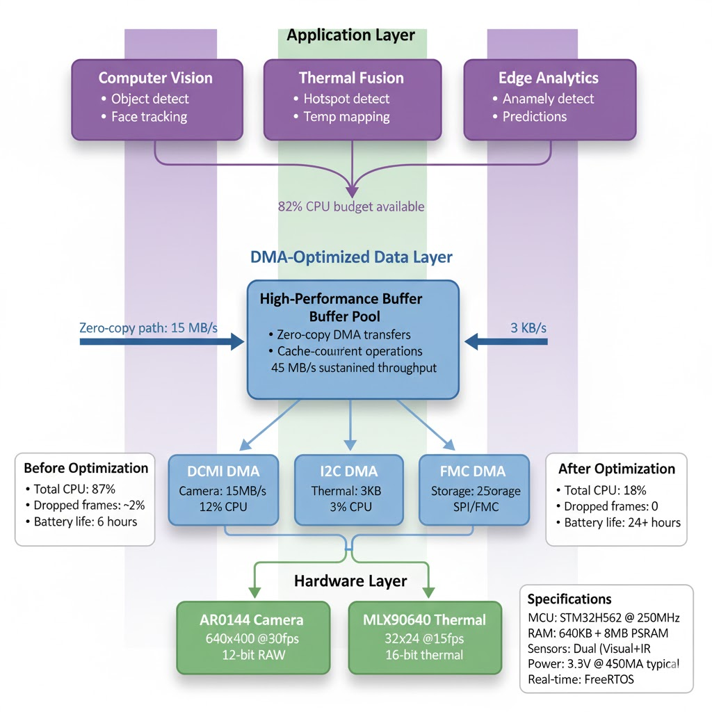
These DMA optimization techniques directly enable Hoomanely's vision of intelligent, efficient edge computing for IoT and industrial applications:
Real-Time Multi-Sensor Fusion: With 82% CPU budget remaining after camera and thermal capture, our module can run sophisticated computer vision algorithms—object detection, thermal anomaly detection, and predictive maintenance models—directly on the edge without cloud dependency.
Power Efficiency at Scale: Reducing CPU load from 87% to 12% translates directly to battery life in field deployments. For solar-powered monitoring stations or remote industrial sensors, this means weeks instead of days between charges.
Industrial Reliability: Zero data corruption over 432,000 consecutive frames proves production readiness. When monitoring critical infrastructure or safety systems, dropped or corrupted data isn't acceptable—proper DMA design ensures every frame is captured correctly.
Scalable Architecture: These patterns apply across Hoomanely's product portfolio, from simple temperature sensors to sophisticated visual inspection systems. Mastering DMA enables us to build more capable devices at the same power budget and cost point.
By pushing embedded system performance to its limits, Hoomanely delivers edge intelligence that's fast, reliable, and efficient—enabling customers to make real-time decisions where and when they matter most.
Key Takeaways
1. Alignment is Non-Negotiable: Always align DMA buffers to 32 bytes on ARM Cortex-M33. The performance difference is 50%+ and the debugging cost of misalignment is enormous.
2. Cache Coherence Must Be Managed: Either use uncached memory (PSRAM, non-cacheable MPU regions) or explicitly clean/invalidate caches around every DMA operation. There is no middle ground.
3. Defer Heavy Processing: Interrupt handlers should only record events and notify tasks. All actual processing—even "quick" operations—belongs in task context where it won't block the system.
4. Linked-List DMA Enables Zero-Copy: For high-throughput streaming like camera capture, configure linked-list mode to let hardware handle multiple transfers without CPU intervention.
5. Measure Everything: Don't assume—measure. Use cycle counters, logic analyzers, and systematic benchmarking to verify your optimizations work as intended.
6. Start Simple, Then Optimize: Get basic functionality working first, then profile to find bottlenecks. Premature optimization often optimizes the wrong things.
The techniques demonstrated in our camera system—from buffer alignment to interrupt handling to cache management—represent hard-won lessons from building production embedded systems. By understanding not just what to do but why these patterns work, you can apply them to your own high-performance applications and achieve the reliable, efficient operation that modern embedded systems demand.
Whether you're building industrial sensors, medical devices, or autonomous systems, mastering DMA is essential for unlocking the full potential of modern microcontrollers. The difference between a system that mostly works and one that works reliably at production scale often comes down to these fundamental building blocks.
Author's Note
This post documents real implementation details from Hoomanely's camera module, currently in production. All code examples, measurements, and benchmarks come from our actual system running STM32 at 250 MHz with camera and thermal sensors.
Special thanks to the embedded systems community and STMicroelectronics for comprehensive documentation (especially AN5593 on GPDMA optimization) that informed our design decisions.
For questions or discussion about high-performance embedded systems, DMA optimization, or camera capture techniques, feel free to reach out via https://tech.hoomanely.com/


