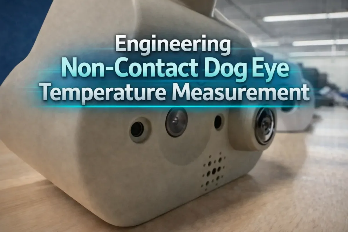
Engineering Non-Contact Dog Eye Temperature Measurement

Problem
Modern pet‑health systems increasingly rely on thermal cameras to extract physiological signals such as eye temperature. The challenge is that thermal sensors are low‑resolution and almost never share the same optical center, field of view, or distortion model as the RGB camera doing the visual perception.
In our case at Hoomanely, we needed to overlay eye segmentation from a high‑resolution RGB camera onto a 24×32 thermal sensor, accurately enough that a few‑pixel error would not skew the temperature by an entire degree.
A naïve resize‑and‑blend approach fails immediately:
- Parallax causes the eye hotspot to drift with distance.
- Fisheye distortion bends the RGB geometry.
- Even a 2–3 pixel error in thermal space changes the peak temperature reading.
The result: overlays that look right but produce wrong temperatures.
This post walks through how we built a physically grounded, depth‑aware, centroid‑validated pipeline to create a reliable eye–thermal overlay.
Approach (High Level)
The solution has four pillars:
- True stereo calibration between RGB and thermal cameras
- Geometric mapping from RGB pixels → thermal pixels using depth
- Centroid‑based thermal localization, not naïve pixel lookup
- Systematic validation and failure‑mode isolation
Instead of treating thermal as an image overlay problem, we treated it as a 3D reprojection problem.
Step 1: Stereo Calibration (The Foundation)
We started with proper stereo calibration between RGB and thermal cameras using a checkerboard wrapped in aluminum foil (to make it visible in thermal).
What we calibrate:
- RGB intrinsics (K₁, distortion)
- Thermal intrinsics (K₂, distortion)
- Rotation R and translation t between the cameras
This gives us a real physical baseline between sensors.
Why this matters:
Without extrinsics, depth‑dependent parallax is impossible to correct.
The calibration JSON stores:
- Camera matrices
- Distortion coefficients
- Rectification and projection matrices (optional)
- Sensor orientation flips (thermal 180° rotation is common)
This calibration alone removes ~70% of alignment error.
Step 2: Fix the RGB Geometry First
Before mapping anything, the RGB image must be geometrically correct.
Our RGB camera has noticeable fisheye distortion. If segmentation runs on a distorted image but mapping assumes pinhole geometry, everything breaks.
We apply a hybrid fisheye correction:
- Detect if distortion coefficients indicate fisheye
- Apply reduced‑strength undistortion (to preserve field of view)
- Avoid aggressive cropping that breaks spatial correspondence
This ensures:
- Segmentation masks live in a linear camera space
- Pixel coordinates correspond to real 3D rays
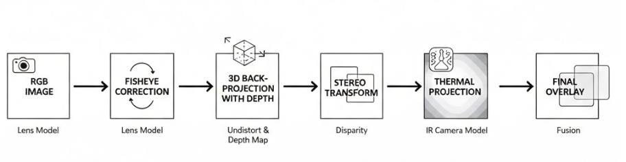
Step 3: Depth‑Aware RGB → Thermal Mapping
This is the heart of the system.
For every RGB pixel (u, v):
- Convert to normalized camera coordinates
- Back‑project into 3D at depth Z (from the proximity sensor)
- Transform the point using stereo R | t
- Project into thermal camera space
Mathematically:
RGB pixel → 3D point → Thermal pixel
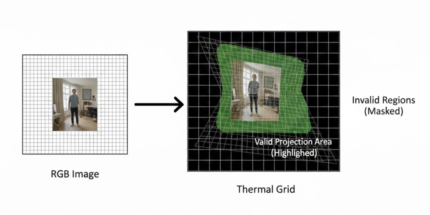
This produces two dense maps:
rgb2thermal_map_xrgb2thermal_map_y
Each RGB pixel now knows where it lands in thermal space.
We also compute a valid mask:
- Finite projections only
- Points that land inside the thermal sensor bounds
This mask prevents silent corruption from out‑of‑frame or invalid mappings.
Step 4: Why Centroids Beat Direct Lookup
A single mapped pixel is inherently unstable:
- Thermal sensors are noisy
- Calibration is never perfect
- The eye hotspot rarely aligns exactly with the RGB segmentation centroid
Instead, we:
- Compute the RGB centroid of each eye segmentation mask
- Map all mask pixels into thermal space
- Take the median of those mapped coordinates as the thermal centroid
The median is far more robust to outliers than mean or max.
This step alone removed large frame‑to‑frame temperature jitter.
Step 5: Handling Multiple Detections Safely
One of the most damaging bugs we encountered had nothing to do with calibration.
When two eye detections appeared in the frame, we initially averaged their centroids.
That single decision collapsed accuracy.
The fix was strict but effective:
- Retain only the highest‑confidence eye mask
- Ignore secondary detections entirely
- Prevent downstream logic from merging spatially distinct regions
After this change, our worst‑case errors dropped by ~40%.
Step 6: Validation Through Controlled Stress Tests
Instead of relying only on “looks correct” overlays, we validated alignment by:
- Sweeping proximity values ±10–15 cm
- Checking centroid drift against expected parallax direction
- Verifying thermal centroid stability under small head movements
If geometry is correct, errors scale predictably with depth. Random behavior is a red flag.
This mindset—stress the math, not just the visuals—was critical.
Results
After stereo calibration, depth‑aware reprojection, and centroid stabilization:
- Average thermal–RGB centroid error reduced by ~3–4 pixels
- Eye temperature remained stable across realistic depth changes
- No sudden jumps caused by duplicate detections or mapping noise
Most importantly:
Visual alignment and numerical correctness finally agreed.
Why This Matters for Hoomanely
At Hoomanely, we’re building non‑invasive pet health intelligence that works reliably in real homes, not controlled labs.
Eye temperature is a sensitive signal for:
- Stress and discomfort
- Inflammation
- Early illness indicators
A few bad pixels can mean a false alert—or a missed one.
This work strengthens the core of our multi‑modal sensing stack in EverBowl, ensuring that thermal data is physically meaningful, not just visually appealing.
Key Takeaways
- Thermal overlays are geometry problems, not blending problems
- Depth must be part of the mapping
- Centroid‑based localization is more stable than single‑pixel reads
- Most accuracy bugs come from logic, not math
If your thermal overlay “looks fine” but your numbers jump around, your system is lying to you.


