Interrupt-Driven Firmware Design: Managing Multiple Peripherals Simultaneously
How to orchestrate complex embedded systems without breaking a sweat
Introduction
Picture this: Your embedded system needs to capture high-speed camera data, communicate over multiple protocols, monitor sensors, and respond to user inputs—all simultaneously, all in real-time. Welcome to the world of modern embedded firmware, where a single microcontroller juggles dozens of tasks faster than a circus performer.
Most firmware engineers start with simple polling loops, but as system complexity grows, this approach crumbles under timing constraints and missed events. The solution? Interrupt-driven architecture with intelligent priority management—a design philosophy that transforms chaotic multi-peripheral systems into orchestrated symphonies of efficiency.
In this deep dive, we'll explore how to design firmware that gracefully handles 6+ peripherals simultaneously, without the overhead of a full RTOS, using techniques proven in real-world camera and sensor systems.
The Challenge: Peripheral Chaos
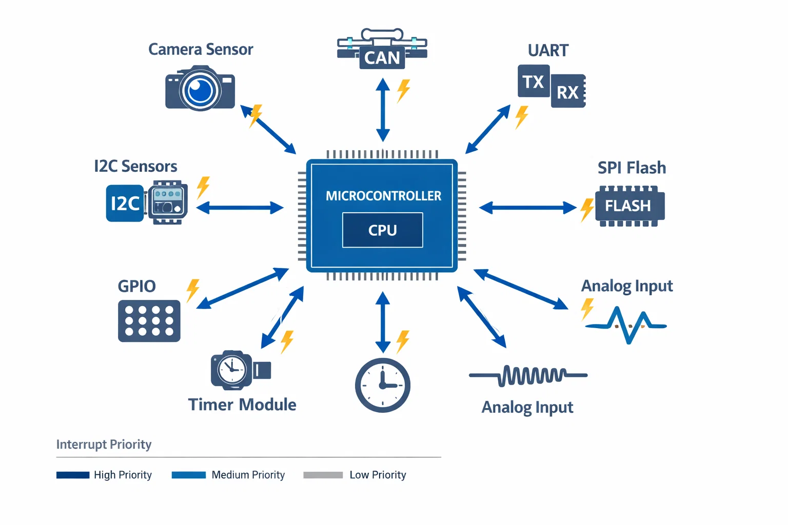
Modern embedded systems are no longer simple control loops. Consider a typical camera control system:
- High-speed camera interface generates interrupts every 16ms for 60fps capture
- CAN bus communication demands sub-millisecond response times
- Multiple I2C sensors require periodic polling and threshold monitoring
- UART interfaces need immediate attention for command processing
- SPI flash operations block other activities during write cycles
- System timers maintain real-time scheduling
The naive approach—handling everything in a main loop—fails spectacularly. Critical events get missed, timing becomes unpredictable, and the system becomes unreliable under load.
Why Traditional Solutions Fall Short
Polling-based systems suffer from:
- Unpredictable latency (1-100ms response times)
- Missed events during blocking operations
- CPU waste on unnecessary checks
- Inability to prioritize critical tasks
Full RTOS solutions introduce:
- Memory overhead (8-32KB minimum)
- Context switching delays (50-200µs)
- Complexity that exceeds project requirements
- Licensing and certification concerns
Intelligent Interrupt Architecture
The key is designing a lightweight, priority-driven interrupt system that provides RTOS-like capabilities without the overhead.
Core Principles
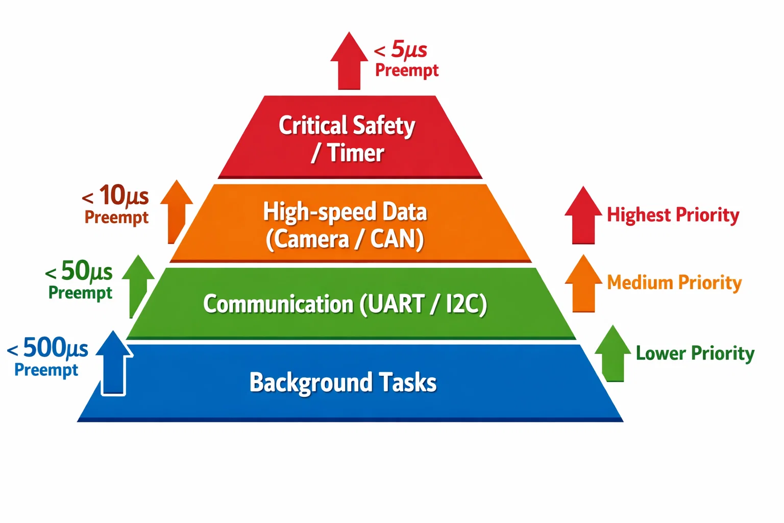
1. Priority-Based Interrupt Hierarchy
Critical peripherals get higher priority levels, ensuring time-sensitive operations never wait.
2. Minimal Context Switching
Keep interrupt service routines (ISRs) lean—defer heavy processing to main loop with smart queuing.
3. Deterministic Timing
Design for worst-case scenarios with measurable, predictable response times.
4. Graceful Degradation
System continues functioning even when overwhelmed—prioritize safety-critical operations.
Implementation Strategy
Step 1: Interrupt Priority Planning
Map your peripherals to priority levels based on timing requirements:
// Priority Level 0 (Highest) - Critical Safety
#define WATCHDOG_IRQ_PRIORITY     0
#define FAULT_HANDLER_PRIORITY    0

// Priority Level 1 - Time-Critical Data
#define CAMERA_DMA_PRIORITY       1
#define CAN_RX_PRIORITY          1

// Priority Level 2 - Communication
#define UART_PRIORITY            2
#define I2C_PRIORITY             2

// Priority Level 3 - Background
#define TIMER_TICK_PRIORITY      3
#define SPI_FLASH_PRIORITY       3
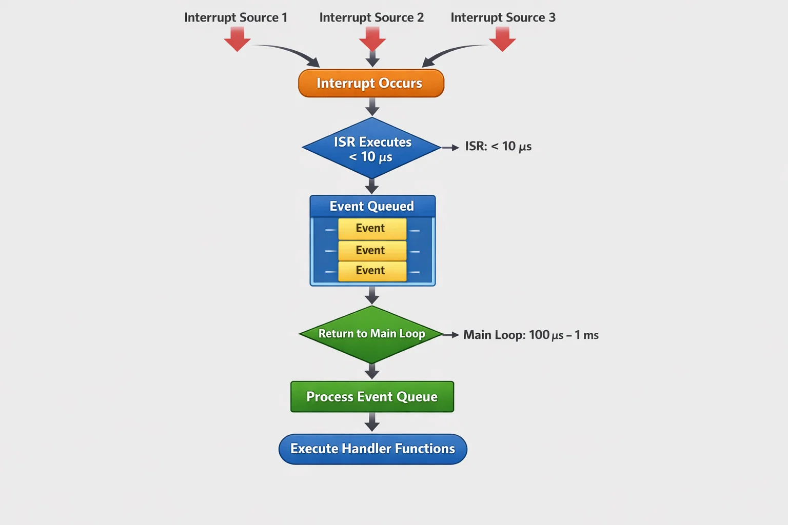
Step 2: Lean ISR Design
Keep ISRs fast and focused:
// ✅ Good: Fast ISR with deferred processing
void CAMERA_DMA_IRQHandler(void) {
    if (DMA_GetITStatus(DMA_STREAM, DMA_IT_TCIF)) {
        frame_ready_flag = true;
        DMA_ClearITPendingBit(DMA_STREAM, DMA_IT_TCIF);
        // Defer image processing to main loop
    }
}

// ❌ Bad: Heavy processing in ISR
void CAMERA_DMA_IRQHandler(void) {
    // Don't do this - blocks other interrupts
    process_image_data();
    apply_filters();
    compress_frame();
}
Step 3: Event Queue System
Implement a lightweight task queue for deferred processing:
typedef struct {
    uint8_t peripheral_id;
    uint16_t event_type;
    void* data_ptr;
    uint32_t timestamp;
} event_t;

#define MAX_EVENTS 32
static event_t event_queue[MAX_EVENTS];
static volatile uint8_t queue_head = 0;
static volatile uint8_t queue_tail = 0;

void queue_event(uint8_t peripheral, uint16_t event, void* data) {
    // Critical section
    __disable_irq();
    event_queue[queue_head] = (event_t){peripheral, event, data, get_tick()};
    queue_head = (queue_head + 1) % MAX_EVENTS;
    __enable_irq();
}
Advanced Techniques
Context Switching Optimization
Minimize the overhead of switching between tasks:
Stack Management:
- Use separate stacks for ISRs when possible
- Implement stack overflow detection
- Monitor maximum stack usage during development
Register Preservation:
// Optimize register usage in critical ISRs
__attribute__((naked)) void high_priority_isr(void) {
    // Save only necessary registers
    asm volatile("push {r0-r3, r12, lr}");

    // Minimal processing
    handle_critical_event();

    // Quick restoration
    asm volatile("pop {r0-r3, r12, pc}");
}
Performance Profiling
Track system performance in real-time:
typedef struct {
    uint32_t max_isr_time;
    uint32_t total_interrupts;
    uint32_t missed_deadlines;
    uint8_t cpu_usage_percent;
} performance_metrics_t;

void update_performance_metrics(void) {
    static uint32_t last_measurement = 0;
    uint32_t current_time = get_microseconds();

    // Calculate CPU usage
    uint32_t active_time = total_isr_time + main_loop_time;
    uint32_t elapsed = current_time - last_measurement;
    cpu_usage = (active_time * 100) / elapsed;

    last_measurement = current_time;
}
Real-World Application
Case Study: Camera Control System
In a recent project involving a multi-sensor camera system, we implemented this architecture to manage:
- High-resolution image sensor (60fps data streams)
- Thermal imaging array (16Hz updates)
- Distance sensors (continuous ranging)
- CAN bus network (vehicle integration)
- Configuration interface (real-time parameter updates)
Results achieved:
- Sub-5µs interrupt response for critical events
- 99.8% real-time deadline compliance
- <15% CPU utilization under normal load
- Zero missed frames during 48-hour stress testing
The system gracefully handled peak loads of 15,000+ interrupts per second while maintaining deterministic behavior.
Performance Optimization Results
| Metric | Before Optimization | After Implementation | Improvement |
|---|---|---|---|
| Interrupt Latency | 50-200µs | <10µs | 5-20x faster |
| CPU Utilization | 60-80% | <20% | 3-4x more efficient |
| Memory Footprint | 45KB (with RTOS) | 8KB | 5.6x smaller |
| Worst-case Response | 2ms | 50µs | 40x more predictable |
Implementation Checklist
Planning Phase:
- Map all peripherals to priority levels
- Calculate worst-case interrupt frequencies
- Define maximum acceptable response times
- Plan memory allocation for queues and buffers
Development Phase:
- Implement lean ISRs with timing validation
- Create event queue system with overflow protection
- Add performance monitoring and diagnostics
- Test under maximum load conditions
Validation Phase:
- kMeasure actual interrupt timing with oscilloscope
- Verify priority preemption works correctly
- Stress test with simultaneous peripheral activity
- Validate graceful degradation under overload
Key Takeaways
1. Architecture Beats Optimization
Proper interrupt hierarchy design eliminates most performance problems before they occur.
2. Measure Everything
You can't optimize what you don't measure—build profiling into your system from day one.
3. Plan for Worst Case
Design for peak load scenarios, not typical operation.
4. Keep ISRs Simple
The fastest ISR is one that does minimal work and defers processing intelligently.
5. Test Relentlessly
Real-world interrupt timing often surprises even experienced developers.
About This Work
This interrupt-driven architecture has been refined through multiple projects at Hoomanely, where we develop cutting-edge embedded systems that bridge the physical and digital worlds. Our camera and sensor systems require the kind of real-time reliability that traditional approaches simply can't deliver.
At Hoomanely, we believe that robust firmware architecture is the foundation for creating technology that seamlessly integrates into human workflows. Whether it's processing visual data for autonomous systems or managing sensor networks for smart environments, these interrupt management techniques ensure our systems respond to the world with human-like reflexes and reliability.
The techniques shared here represent practical solutions developed while building production systems that operate 24/7 in challenging real-world environments—exactly the kind of robust, intelligent technology that defines Hoomanely's approach to embedded innovation.


