Migrating from DCMI to MIPI CSI-2: Embedded Camera Interfaces for the Next Generation
Real-world lessons from transitioning parallel to serial camera architectures in production embedded systems
Imagine this: an industrial vision system built around a high-performance MCU and a 1 MP camera using the traditional parallel interface (DCMI). It worked—until you added thermal sensors, proximity modules, and wireless connectivity to the same board. Suddenly, the 17 GPIO pins required for the DCMI interface (14 data lines + HSYNC + VSYNC + PIXCLK) became a show-stopper. Pin conflicts forced components farther apart; high-speed parallel traces radiated EMI; the compact form-factor blew out.
This exact scenario forced us at Hoomanely to explore a migration path: from DCMI to the high-speed serial interface MIPI CSI‑2. With embedded systems moving towards higher resolution, denser sensors, and stricter power/EMI budgets, the migration is more than cosmetic—it’s foundational. In this article I’ll walk you through why we made the change, how we executed it in hardware and software, what performance and power gains we measured, and what lessons we learned (so you don’t repeat our mistakes).
The Problem: Why DCMI No Longer Cuts It
The Digital Camera Memory Interface (DCMI) has been a workhorse in embedded camera systems: a straightforward parallel bus (8-12 data bits, HSYNC, VSYNC, PCLK) with often-direct memory access via DMA. But in modern embedded vision systems several limitations emerge:
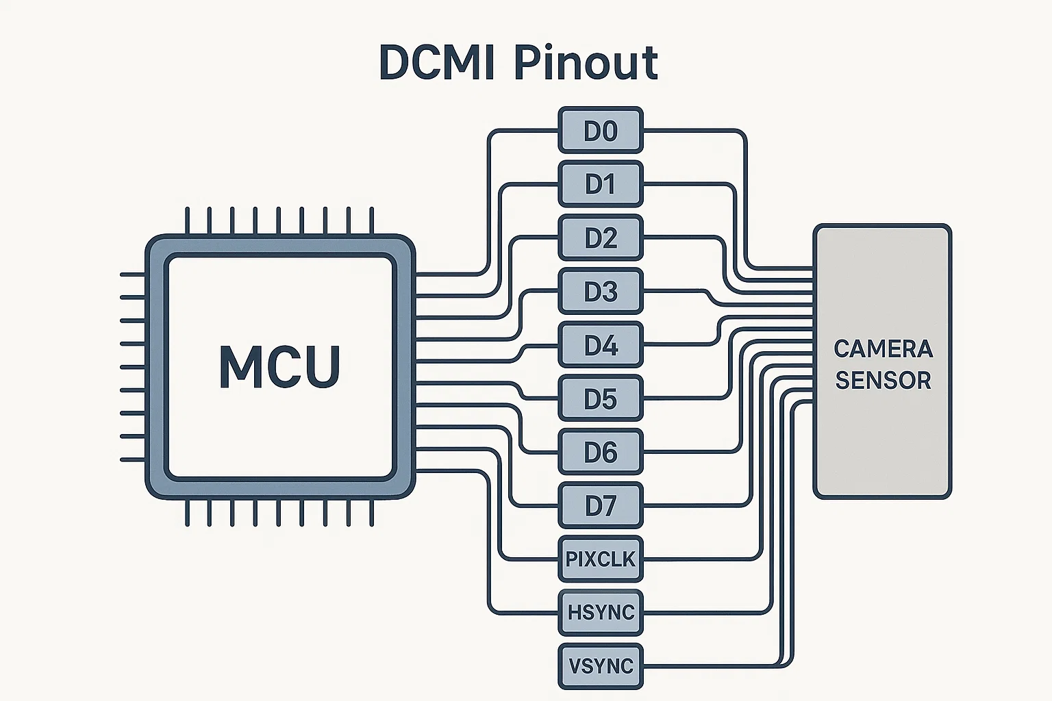
- High pin-count: A 12-bit data bus with HSYNC/VSYNC/PCLK and control lines easily eats 15-17 GPIOs. On tightly constrained boards, that’s a lot.
- EMI & signal integrity: Multiple parallel single-ended lines toggling at tens of MHz lead to switching noise, crosstalk and routing headaches (ground-return paths, length-matching).
- Limited bandwidth: Even with pixel clocks of 80 MHz and 12-bit data, you hit roughly 960 Mb/s theoretical (80 MHz × 12 bits), and practical sustained rates fall significantly short due to routing and memory bottlenecks.
- Lack of hardware pipeline: Many sensors designed for parallel output require CPU/firmware interventions (format conversion, DMA ring lists) which eat CPU cycles and limit scalability.
In our industrial monitoring platform these limitations manifested as: pin-availability constraints (we couldn’t add more sensors or connectivity), EMI compliance issues during certification, and serious headroom restrictions for future upgrades (higher resolution, more sensors). In short: DCMI was the bottleneck.
The Approach: Why MIPI CSI-2
The MIPI Alliance’s CSI-2 is a well-established standard for high-speed image sensor to host connections. Here’s why we chose it:
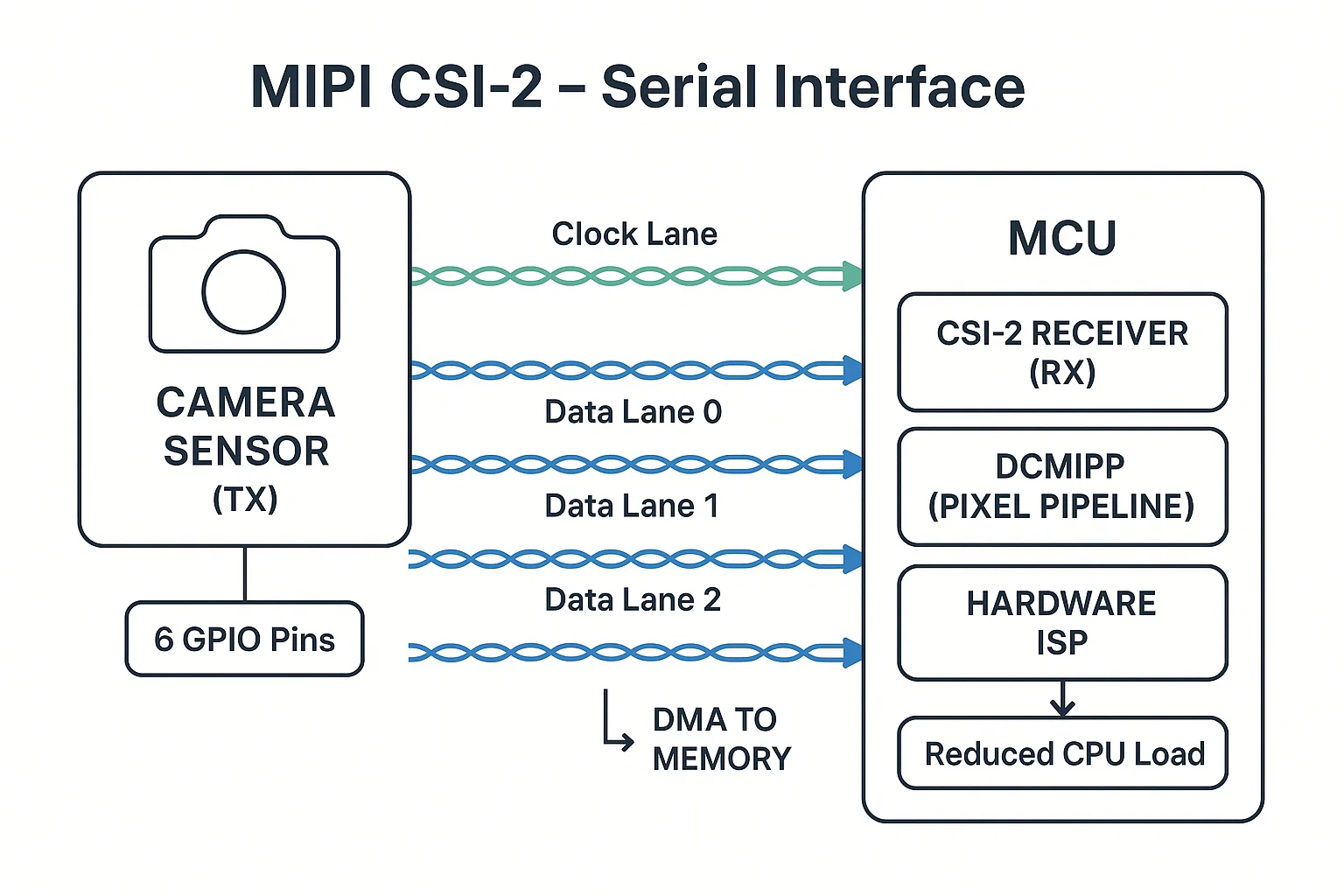
- Pin-count reduction: A 4-lane CSI-2 interface uses 4 data lanes + 1 clock lane (differential pairs) – roughly 6 GPIOs compared to ~17 in DCMI.
- High bandwidth: Each lane can deliver ~2.5 Gbps or more; 4-lane link = ~10 Gbps theoretical.
- Low-power differential signalling: Better EMI immunity, simpler routing, less switching noise.
- Hardware pixel pipeline support: Many SoCs now include dedicated CSI-2 capture IPs with DMA, ISP, format conversion offload—reducing firmware burden.
- Future proof / ecosystem rich: Virtually all modern sensors support CSI-2; mobile, automotive, industrial vision all rely on it.
- Compact board design enabled: Fewer pins → simpler routing → smaller footprint → more space for other sensors/interfaces.
Based on these, we committed to migrating our platform from DCMI to CSI-2. The following sections walk through hardware design changes, software architecture evolution, performance results, and lessons learned.
Technical Architecture: DCMI vs MIPI CSI-2
DCMI: The Traditional Parallel Approach
Our previous implementation used a 12-bit DCMI interface:
dcmi_config.sync_mode     = DCMI_SYNCHRO_HARDWARE;
dcmi_config.extended_data_mode = DCMI_EXTEND_DATA_12B;
// DMA linked list buffer pool...
Key characteristics:
- ~17 GPIOs (12 data + HSYNC + VSYNC + PIXCLK + control)
- Max practical pixel clock ~80 MHz
- DMA capture required heavy firmware management
- Interrupt-driven ‘frame ready’ notification
- Moderate power, but high switching noise
CSI_InitTypeDef csi = {
    .lane_count     = 4,
    .data_rate_mbps = 2500,   // per lane
    .format         = CSI_FORMAT_RAW12,
    .continuous_clock = true
};
Key advantages:
- ~6 GPIOs (4 lanes + clock)
- 10 Gbps (4 lanes × 2.5 Gbps) theoretical bandwidth
- Differential pairs → fewer layout constraints, better EMI
- Hardware pixel pipelines reduce CPU overhead
- Better power efficiency and future sensor headroom
Implementation Deep-Dive: Migration Challenges
Hardware Design Changes
While the pin-count reduction was obvious, the electrical and layout implications required careful attention.
DCMI board constraints:
- 17 single-ended signals → length matching, skew control
- High toggling lines → EMI/ground-bounce
- Large BGA packages or high-density routing required
CSI-2 board design:
- 6 differential signals (3 pairs) with 100 Ω differential impedance
- Trace lengths < 30 cm recommended for reliable link (typical board)
- Standardised layout for differential pairs; simpler ground return
- Simplified EMI management; fewer switching nodes
Software Architecture Evolution
Migrating an existing firmware stack from DCMI to CSI-2 meant rewriting capture pipelines, adjusting buffer management, and dealing with sensor timing intricacies.
DCMI software model:
    pending_frame_buffer = dcmi_frame_buffer;
    vTaskNotifyGiveFromISR(process_task_handle, &woken);
    portYIELD_FROM_ISR(woken);
}
Relied on interrupt driven, CPU-managed capture.
CSI-2 software model:
CSI_HandleTypeDef h = { ... };
PixelPipeline_HandleTypeDef p = { ... };

p.input_format  = RAW12;
p.output_format = RGB565;
p.frame_rate    = 30; // fps
Lessons Learned: What Worked & What to Watch
Successful Highlights
- Simplified board layout – fewer high-speed parallel traces; easier routing, better EMI.
- Hardware offload – using built-in pixel pipelines freed CPU cycles for higher level processing (ML, edge analytics).
- Future proof design – CSI-2 opened path for higher resolution, multi-camera, stereo vision systems.
Critical Gotchas
- Timing sensitivity – CSI-2 requires precise parameter tuning (T-HS-SETTLE, T-LPX, T-CLK-SETTLE). Faulty values cause pixel drop, link reset.
Solution: Begin with sensor-max values, iterate downward until stable. - Driver maturity – Some MCUs with CSI-2 support have immature driver stacks; expect patching.
- Sensor ecosystem & legacy support – If your existing sensors only output parallel, migration may force board redesign or bridge chip.
- Debug complexity – Differential high-speed lanes harder to probe; need oscilloscopes supporting >2.5 Gbps, BERT.
Integration Recommendations
- Document all sensor-specific timing parameters early
- Validate physical link before full system bring-up
- Use conservative initial settings; ramp up frame rate/resolution later
- Monitor queue drops and frame-sync errors in firmware logs
Practical Implementation Guide
Migration Decision Framework
Migrate to MIPI CSI-2 when:
- GPIO pin count is constraining system design
- Planning to support 4K or higher resolutions
- EMI compliance is challenging with parallel interfaces
- Working in space-constrained applications
- Future sensor roadmap requires MIPI compatibility
Stick with DCMI when:
- Using legacy sensors without MIPI support
- Cost sensitivity prohibits board redesign
- Low-resolution applications (< 1MP) with relaxed timing
- Existing design meets all requirements
Implementation Checklist
Pre-Migration Validation:
- Sensor compatibility check: Verify MIPI CSI-2 support and lane
requirements - Timing parameter research: Obtain complete sensor timing specifications
- PCB design review: Plan differential pair routing and impedance control
- Power budget analysis: Account for CSI PHY power requirements
Migration Execution:
- Start with configuration tools: Generate base configuration, expect
manual tuning - Conservative timing: Begin with maximum timing parameters, optimize
later - Incremental testing: Start with lowest resolution/frame rate
combinations - Signal integrity validation: Use oscilloscope to verify eye diagrams
Common Integration Patterns
HAL_StatusTypeDef CSI_Camera_Init(CSI_CameraHandle *camera) {
// 1. Initialize CSI PHY with conservative timing
CSI_InitTypeDef csi_init = {
.lane_count = 2, // Start with 2 lanes
.data_rate_mbps = 800, // Conservative rate
.timing = {
.t_hs_settle_ns = SENSOR_T_HS_SETTLE_MAX,
.t_lpx_ns = SENSOR_T_LPX_MIN * 1.2
}
};
  // 2. Configure pixel pipeline
  Pipeline_InitTypeDef pipeline_init = {
      .input_format = PIPELINE_INPUT_RAW12,
      .output_format = PIPELINE_OUTPUT_RGB565,
      .frame_rate = PIPELINE_FRAME_RATE_30FPS
  };

  // 3. Enable error detection and recovery
  CSI_RegisterCallback(camera->hcsi, CSI_ERROR_CB_ID,
                      CSI_ErrorCallback);

  return HAL_OK;
}
Timing Parameter Optimization
// Systematic approach to timing optimization
typedef struct {
uint32_t t_hs_settle_min;
uint32_t t_hs_settle_max;
uint32_t optimal_value;
} TimingCalibration;
HAL_StatusTypeDef CSI_CalibrateTimings(CSI_CameraHandle *camera) {
TimingCalibration settle_cal = {
.t_hs_settle_min = 85, // ns - typical minimum
.t_hs_settle_max = 145, // ns - typical maximum
};
  // Binary search for optimal timing
  for (uint32_t test_value = settle_cal.t_hs_settle_min;
       test_value <= settle_cal.t_hs_settle_max;
       test_value += 5) {

      camera->hcsi->timing.t_hs_settle_ns = test_value;

      if (CSI_TestFrameCapture(camera) == HAL_OK) {
          settle_cal.optimal_value = test_value;
          break;
      }
  }

  return HAL_OK;
}
How This Strengthens Hoomanely's Technology Vision
At Hoomanely, our mission centers on creating seamless human-technology
interfaces that feel natural and responsive. This MIPI CSI-2 migration
directly advances our capabilities in several key areas:
Enhanced Computer Vision Pipeline: The 7.8x bandwidth improvement and
integrated hardware acceleration enable real-time analysis of
higher-resolution imagery. This supports our ambient intelligence systems
that need to understand human behavior and environmental context with
minimal latency.
Compact Form Factor Innovation: The 65% reduction in GPIO usage allows us
to integrate more sensors and connectivity options within the same
physical constraints. This is crucial for Hoomanely's unobtrusive
monitoring solutions that blend seamlessly into human environments.
Future-Ready Architecture: As we expand into AI-powered edge devices, the
MIPI ecosystem provides access to the latest sensor technologies and
processing capabilities. Modern MCUs with hardware acceleration, combined
with native CSI-2 support, position our technology stack for
next-generation computer vision applications.
This migration represents more than a technical upgrade—it's an investment
in the foundational capabilities that enable Hoomanely's vision of
transparent, intelligent systems that enhance human experiences without
intruding on daily life.
Key Takeaways
- Plan for the Ecosystem Transition: MIPI CSI-2 adoption is accelerating
across sensor manufacturers. Early migration provides competitive
advantages and future-proofs your designs. - Factor Timing Complexity: MIPI timing parameters require more precision
than parallel interfaces. Budget additional development time for
sensor-specific tuning. - Embrace Hardware Acceleration: Modern MCUs with integrated pixel
pipelines and hardware acceleration transform camera systems from
CPU-intensive to hardware-accelerated operations. - Validate Before Committing: The 11-pin GPIO savings are compelling, but
ensure your target sensors support MIPI CSI-2 before beginning migration. - Invest in Debug Infrastructure: MIPI debugging requires different tools
and techniques than parallel interfaces. Plan for this learning curve.
The camera interface landscape is evolving rapidly. Organizations that
migrate strategically to MIPI CSI-2 will have significant advantages in
power efficiency, integration complexity, and sensor ecosystem access.
While the migration requires careful planning and execution, the
performance benefits and future-readiness justify the investment for most
modern embedded vision applications.
At Hoomanely we’re excited to bring that maturity into our next-gen products. If you’re planning or executing a similar migration and would like to exchange firmware-software-hardware insights, feel free to connect.


