PCB Flex for Sensors: Designing Reliability Under Movement
When Motion Is Inevitable, Instability Is Not
In modern embedded systems, motion is no longer an edge case—it is the operating condition. Wearables flex with the body. Smart appliances vibrate, tilt, and experience repeated micro-deflections. Sensor-rich products interact continuously with their physical environment. In these systems, the PCB is not a static artefact mounted once and forgotten; it is a mechanical participant in the product’s lifecycle.
At Hoomanely, several vBus-based products rely on flex PCBs to position sensors exactly where rigid boards cannot reach. But flexibility introduces a paradox: sensors demand mechanical stability, while flex circuits invite movement. Accelerometers, load sensors, microphones, and capacitive sensors are all sensitive—not just to electrical noise, but to mechanical strain, micro-bending, and shifting reference frames.
Our design philosophy resolves this tension deliberately. Flex PCBs are not treated as “bendable wires,” nor as convenience connectors. They are engineered mechanical structures whose geometry, material stack-up, routing strategy, and mounting interfaces are tuned to preserve sensor integrity under motion. This article outlines how we design flex-based sensor systems that remain electrically precise and mechanically reliable throughout their operational life.
Flex Is a Mechanical System, Not Just an Electrical One
A flex PCB behaves less like a board and more like a compliant beam. Every bend introduces strain, every vibration excites resonant modes, and every mounting point becomes a stress concentrator. For sensor systems, these effects directly influence signal quality.
Mechanical deformation can:
- Alter sensor alignment and orientation
- Introduce micro-strain into MEMS structures
- Change parasitic capacitance and impedance
- Modulate grounding references
- Create low-frequency noise indistinguishable from real signals
Recognising this, our flex designs start with a mechanical intent. Before routing signals, we define how the flex will move, where it must remain rigid, and how strain is allowed to flow through the structure without intersecting sensitive regions.
Flex is permitted—but only where motion is benign.
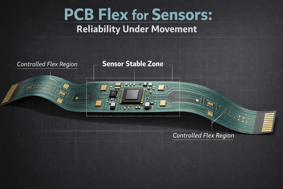
Defining Stable Zones and Compliant Zones
A foundational principle in our flex designs is mechanical zoning.
Sensor Placement Zones
Sensors are always placed in mechanically stable regions:
- Flat, neutral-strain areas
- Located away from bend lines
- Supported by rigid backing or local stiffeners
- Positioned where the enclosure contact defines repeatable geometry
These zones behave mechanically like rigid PCBs, even though they are part of a flex assembly.
Compliant Transition Zones
Flexibility is intentionally confined to narrow transition regions:
- Between modules or structural elements
- Away from sensor footprints
- With controlled bend radius and curvature
- Free of copper planes, vias, and dense routing
By separating where movement occurs from where measurement occurs, we prevent mechanical energy from coupling into sensor behaviour.
Material Stack-Up as a Reliability Lever
Flex reliability is fundamentally governed by material choices. For sensor-critical designs, we avoid generic flex constructions and instead specify stack-ups that prioritise dimensional stability.
Key considerations include:
- Polyimide thickness chosen to balance flexibility with stiffness
- Copper thickness is minimised in bend areas to reduce strain
- Adhesive systems selected for long-term creep resistance
- Coverlay openings are carefully controlled to avoid stress risers
In sensor zones, copper is distributed symmetrically to keep the neutral axis centred, minimising strain during unavoidable micro-deflections. In bend zones, copper is thinned, staggered, or selectively removed to allow smooth curvature without work-hardening.
Material behaviour over time matters. Our designs assume thousands of motion cycles, temperature variation, and long-term mechanical relaxation—and remain stable under all of them.
Routing Strategies That Respect Motion
Electrical routing on flex PCBs cannot follow rigid-board intuition. Trace orientation, copper density, and reference continuity all influence how movement translates into electrical artefacts.
For sensor signals:
- Traces run perpendicular to bend axes where possible
- Differential sensor pairs are tightly coupled and symmetrically routed
- Ground references are continuous but selectively narrowed in flex regions
- High-impedance sensor nodes are kept away from bend transitions
Power and digital buses are routed to tolerate impedance variation without injecting noise into sensor paths. The goal is not merely electrical correctness in a static state, but electrical invariance under motion.
When the flex moves, the signal does not.
Mechanical Mounting as Signal Conditioning
Mounting strategy is one of the most underestimated aspects of flex sensor reliability. How the flex is constrained—or allowed to float—defines how mechanical stress is distributed.
In vBus products:
- Sensor flex sections are mechanically registered to the enclosure
- Hard datum points define orientation and position
- Soft constraints allow micro-movement without stress buildup
- Adhesive pads are placed away from sensor elements to avoid strain coupling
This approach ensures that sensors “see” the same mechanical world every time, even if the surrounding system moves. Motion occurs where it is harmless; measurement occurs where it is repeatable.
Managing Vibration and Micro-Motion
Movement is not always visible. Low-amplitude vibration can be more damaging to sensor performance than large, infrequent bends.
To mitigate this:
- Flex lengths are tuned to avoid resonant frequencies in operational bands
- Mass distribution near sensors is controlled to damp vibration
- Stiffeners are used not just for strength, but for dynamic stability
- Cable-like flex sections are avoided near sensitive components
The objective is a mechanically quiet environment. When the system vibrates, the sensor platform remains inert.
Integration with the vBus Modular Architecture
Flex PCBs do not exist in isolation. In vBus systems, they form part of a modular, serviceable architecture.
This imposes additional constraints:
- Connectors must tolerate repeated mating without transferring stress
- Flex routing must accommodate module removal and replacement
- Sensor calibration must remain valid after service operations
- Mechanical tolerances must survive real-world handling
By designing flex assemblies as first-class modules—with defined interfaces, controlled motion paths, and predictable mechanical behaviour—we ensure that reliability extends beyond the lab into the field.
Flex does not become the weak link in a modular system.
Reliability as a Design Outcome, Not a Test Result
Reliability under movement is not achieved by testing flex designs until they fail less often. It is achieved by embedding mechanical intent into the design from the first outline.
When sensor performance remains stable across:
- Continuous motion
- Repeated service cycles
- Temperature variation
- Long operational lifetimes
…it is because the flex PCB was never treated as an afterthought.
At Hoomanely, flex designs are reviewed with the same rigour as power integrity, thermal performance, and signal integrity. Mechanical behaviour is modelled, constrained, and validated as part of the electrical design process—not after it.
Conclusion: Precision That Moves Without Drifting
Flex PCBs enable form factors and sensing capabilities that rigid boards cannot. But in sensor-driven systems, flexibility must be deliberate, disciplined, and mechanically informed.
By zoning motion, stabilising sensor regions, engineering material behaviour, and integrating flex into the broader vBus mechanical architecture, we build products that move through the real world without letting movement distort measurement.
This is not flexibility for convenience.
It is flexibility engineered for trust.
When a sensor is mounted on flex and still behaves as if it were anchored in stone—that is when flex PCB design has succeeded.


