Preventing Unsafe Reconfiguration While Subsystems Are Active
Introduction
Modern embedded products are becoming increasingly modular.
A single hardware platform may support:
- Multiple sensor configurations
- Different communication modules
- Optional accessories
- Replaceable compute modules
- Expandable peripheral boards
This flexibility improves product scalability, but it introduces a hidden reliability challenge:
What happens when someone tries to change the system configuration while a subsystem is still active?
In early prototypes, this usually appears as a software problem.
A firmware command changes a mode.
A driver disables a peripheral.
A configuration value updates.
Everything seems controlled.
Until the real product environment appears.
A user reconnects a module while power is present.
A factory operator changes a setting before initialization completes.
A service technician replaces a subsystem without fully shutting down the device.
A communication module switches modes while the RF path is active.
A sensor configuration changes while acquisition is running.
These situations create conditions where software timing alone cannot guarantee safety.
The hardware must understand when a transition is allowed.
At Hoomanely, reconfiguration is treated as a controlled state transition, not simply a software command.
A subsystem should not change because someone requested it.
It should change only when the hardware confirms:
- The current state is safe
- Dependencies are inactive
- Power conditions are valid
- No conflicting operation is running
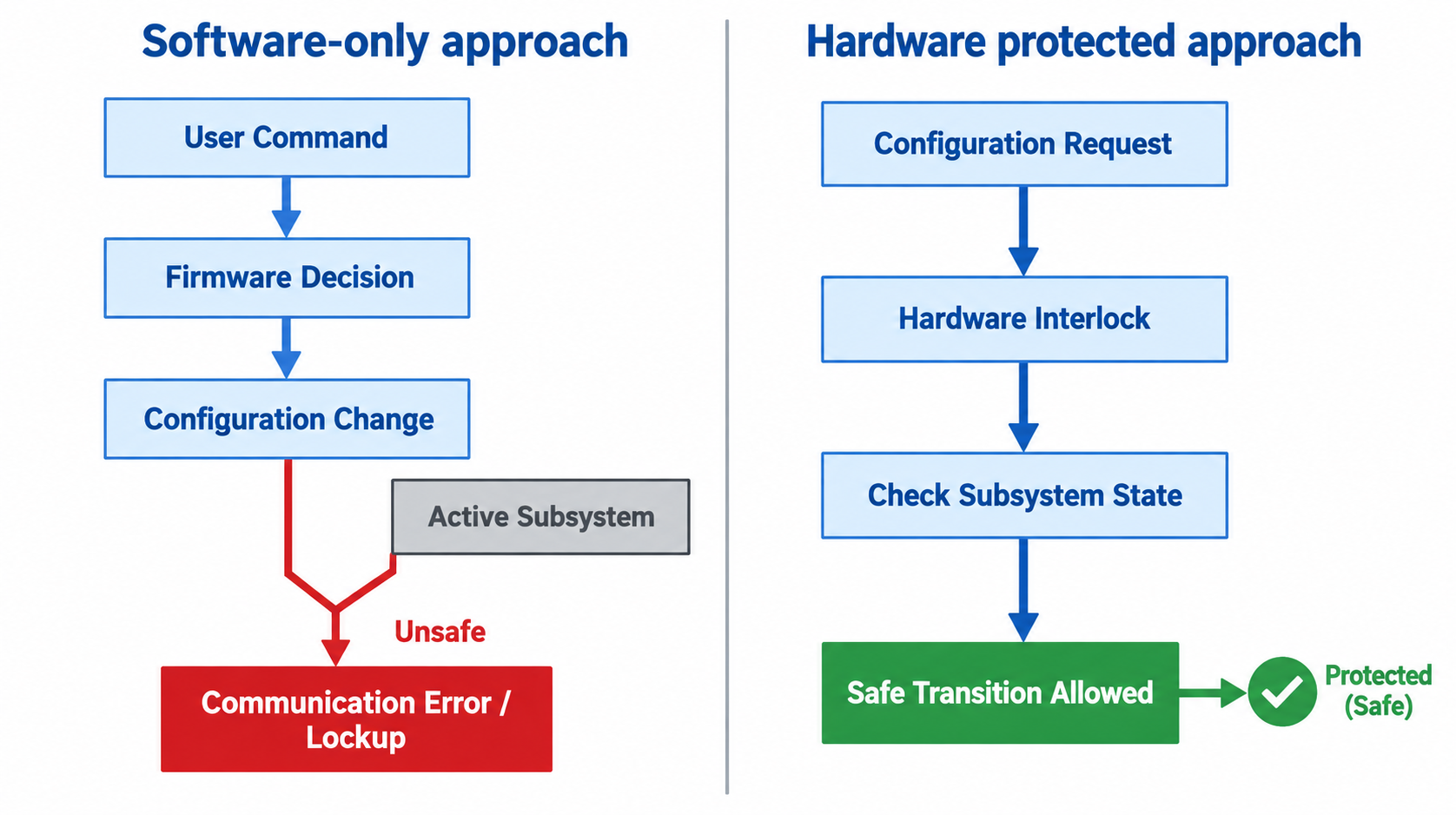
Why Software-Only Reconfiguration Control Fails
A common architecture looks like this:
User Command

      ↓

Firmware Decision

      ↓

Disable Peripheral

      ↓

Change Configuration
This works under ideal conditions.
However, hardware does not always operate in ideal sequences.
Consider a camera module.
Firmware decides:
"Stop camera → Change interface mode → Restart camera"
But between these steps:
- The sensor clock is still running
- The power rail is still enabled
- Data lines are active
- Another subsystem is accessing the bus
The configuration change happens while the system is electrically active.
The result can be:
- Bus contention
- Corrupted communication
- Peripheral lockup
- Unexpected current spikes
- Permanent hardware damage in extreme cases
The problem is not that firmware is incorrect.
The problem is that firmware is assuming a safe transition.
Hardware should verify that assumption.
Designing Hardware Lockouts Around Active States
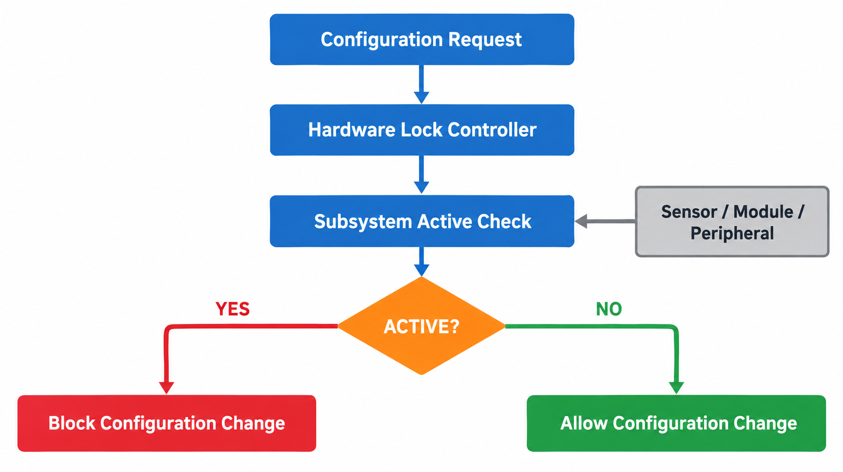
A hardware lockout creates a physical barrier against unsafe changes.
The principle is simple:
If the subsystem is active, the configuration path should be blocked.
Example:
Configuration Request

        |

        ↓

Hardware Lock

        |

Subsystem Active?

   YES        NO

 Block     Allow Change
The lock condition can be generated using:
- Power-good signals
- Enable status
- Clock activity detection
- Busy signals
- Hardware state machines
For example:
A communication module supports two operating modes:
- High-speed data mode
- Low-power standby mode
The mode-select signal should not directly control the module.
Instead:
Mode Request

      |

Hardware Interlock

      |

Is Module Idle?

      |

Enable Mode Change
The hardware decides when the change is allowed.
Live-State Interlocks: Knowing When a System Is Busy
Many failures occur because the system does not know the actual operating state.
A command may say:
"Disable sensor"
But electrically:
- Conversion is still running
- Data transfer is incomplete
- Clock is still active
A live-state interlock creates awareness.
Typical hardware status signals:
- ACTIVE
- BUSY
- DATA_VALID
- FRAME_SYNC
- POWER_GOOD
- CLOCK_VALID
- RESET_DONE
These signals create a real hardware view of subsystem status.
Example:
A thermal camera module:
Camera Enable

      +

Frame Active

      +

Data Transfer Active

          |

          ↓

Configuration Lock
While frames are being transferred:
Configuration changes are blocked.
Only after the system reaches a safe idle state:
Frame Complete

↓

Sensor Idle

↓

Allow Reconfiguration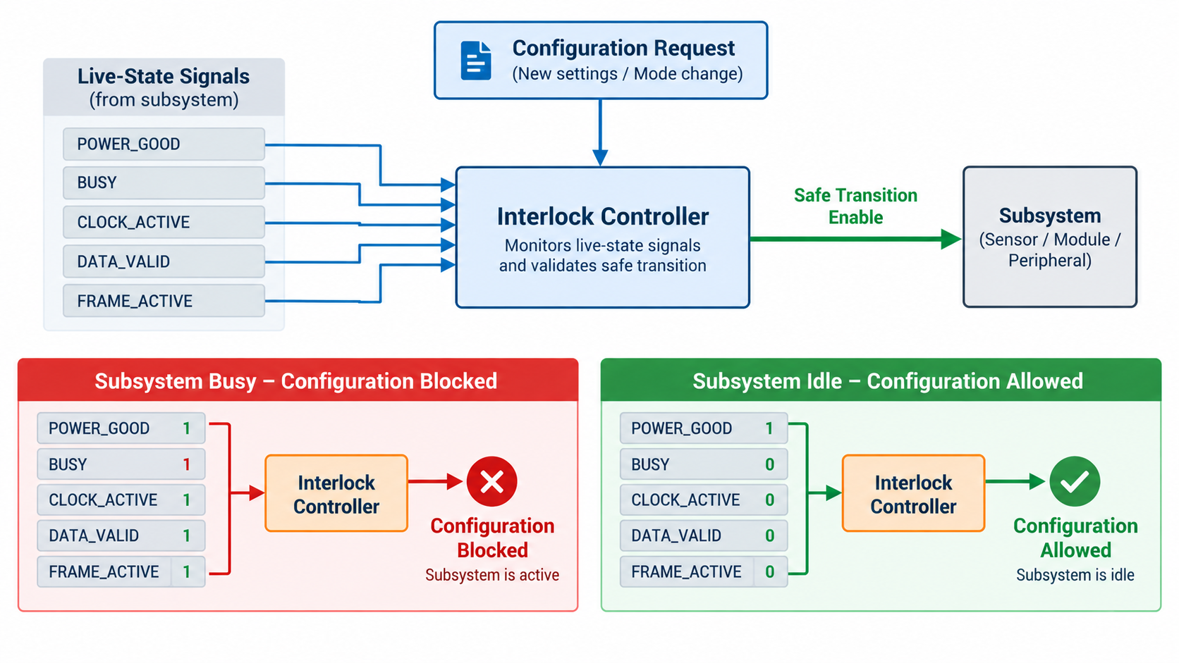
Blocking Unsafe Modes Before They Reach Hardware
A common mistake in modular products is allowing invalid combinations.
Example:
A system supports:
Mode A:
High-speed communication
Mode B:
Low-power communication
But both modes require different:
- Power rails
- Clock settings
- Pin configurations
A software error may accidentally enable both.
Without hardware protection:
Mode A Enable

+

Mode B Enable

        ↓

Conflict
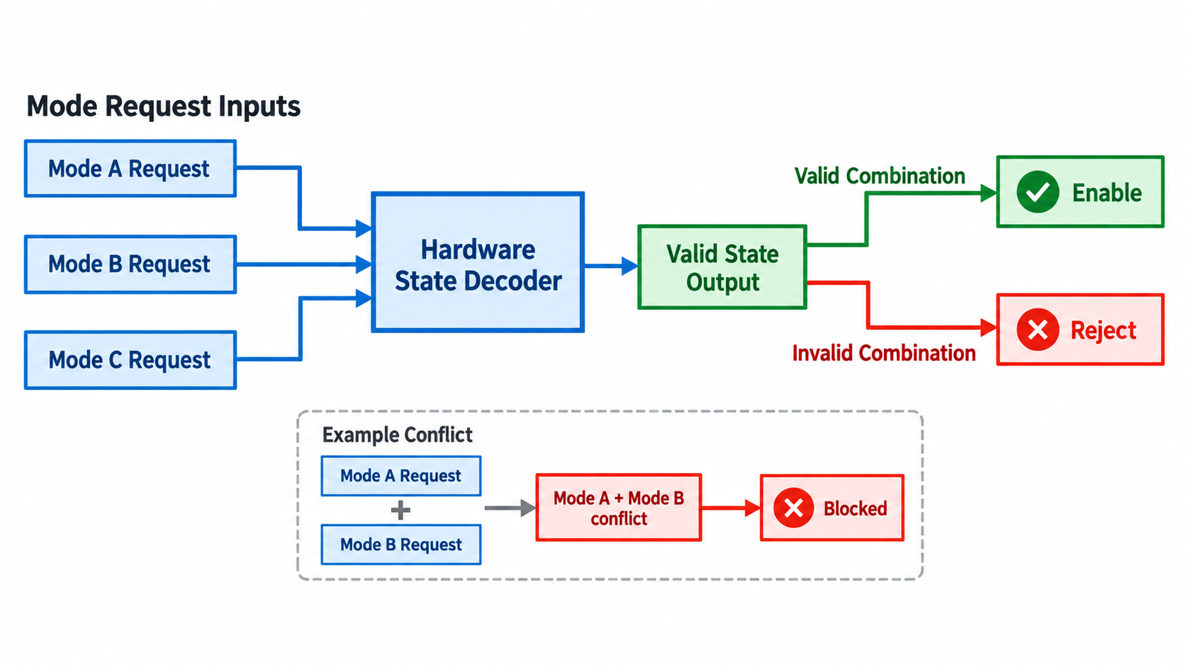
A better architecture:
Mode A Request
        |
        |
        ↓
 Hardware Decoder
        |
        |
        ↓
 Valid State Only
The hardware accepts only approved states.
Invalid combinations are rejected.
This approach is especially important in:
- FPGA systems
- Modular controllers
- Multi-radio products
- Motor control systems
- High-current devices
Protecting Power and Signal Integrity During Reconfiguration
Reconfiguration is not only a logical problem.
It is an electrical event.
Changing subsystem states can create:
- Current transients
- Signal glitches
- Floating inputs
- Uncontrolled startup conditions
A robust architecture controls the transition sequence.
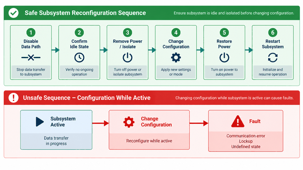
Example:
Unsafe:
Change Signal Mode

↓

Switch Power

↓

Reset Device
Safe:
Disable Data Path

↓

Confirm Idle

↓

Remove Power

↓

Change Configuration

↓

Apply New Power

↓

Restart Subsystem
The hardware sequence ensures that electrical conditions change gradually.
Hardware-Enforced Safe Switching in Modular Architectures
Modular systems need stronger protection because modules may be added, removed, or replaced.
A carrier board may contain:
- Compute module
- Sensor module
- Communication module
Each module should provide:
- Presence detection
- Ready status
- Power enable control
- Identification
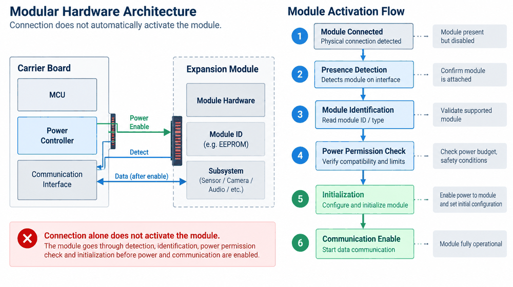
Example:
Module Inserted

      ↓

Presence Detected

      ↓

Power Allowed?

      ↓

Initialize

      ↓

Enable Communication
The module should not immediately become active just because it is connected.
The architecture controls the activation sequence.
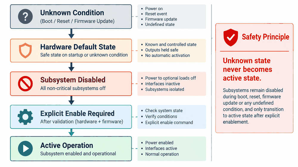
Designing Fail-Safe Defaults
A critical principle in hardware architecture:
Unknown state should never become an active state.
During:
- Boot
- Reset
- Firmware update
- Communication failure
Control signals may temporarily float.
If these signals directly control subsystem modes, unexpected activation can occur.
A safer design:
Default state:
No Configuration

        ↓

Subsystem Disabled

        ↓

Explicit Enable Required
Hardware defaults should prefer:
- Disabled
- Safe
- Low power
- Isolated
The system should require a deliberate transition into an active mode.
Hoomanely Design Perspective
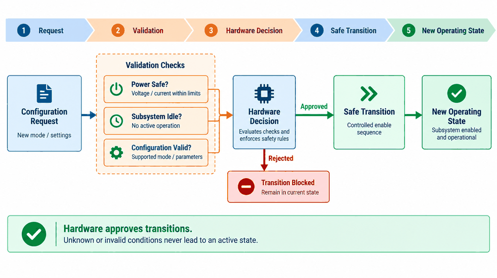
At Hoomanely, configuration changes are considered part of the hardware state machine.
A product should not depend on software discipline alone.
Firmware can request.
Hardware should approve.
This approach changes the design question.
Instead of:
"How do we switch this feature?"
The question becomes:
"Under what conditions is switching this feature safe?"
The answer should exist inside the hardware architecture.
Good designs define:
- Who controls the transition
- Who validates the transition
- What prevents unsafe combinations
- What happens when something goes wrong
A reliable product does not assume perfect sequences.
It creates boundaries that make incorrect sequences difficult to execute.
Conclusion
Modern products need flexibility, but flexibility without control creates failure paths.
Unsafe reconfiguration can cause:
- Communication failures
- Data corruption
- Power instability
- Difficult field debugging
Hardware lockouts prevent invalid actions.
Live-state interlocks ensure changes happen only during safe conditions.
Unsafe-mode blocking prevents conflicting configurations.
Controlled transition paths protect power and signal integrity.
The goal is not restricting the system.
The goal is making flexibility predictable.