Programming at Scale: Engineering a Universal Manufacturing Platform with vBus
Introduction: Reimagining Manufacturing Infrastructure
At Hoomanely, we've always believed that great hardware deserves equally great manufacturing infrastructure. When we developed the vBus ecosystem—our standardized communication architecture for modular System-on-Modules—we immediately recognized an extraordinary opportunity: if our products could speak a universal language, why shouldn't our manufacturing systems do the same?
This insight led us to develop the vBus Universal Programming and Testing Jig, a groundbreaking manufacturing platform that unifies programming, testing, and validation across our entire product portfolio. Rather than accepting the traditional approach of building custom fixtures for each module type, we asked a more ambitious question: What if we could design a single, intelligent platform that automatically adapts to any SoM in our ecosystem?
Today, I want to share how we engineered this breakthrough—the architecture behind it, the capabilities it enables, and how it transforms manufacturing from a constraint into a competitive advantage.
The Vision: A Unified Manufacturing Platform
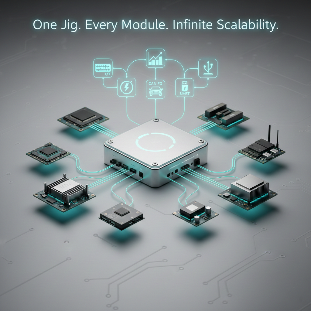
Our vision was elegantly simple but technically ambitious: create a programming and testing platform that leverages the vBus standard as its foundation, enabling seamless support for CPU SoMs, Peripheral SoMs, Communication SoMs, and any future module types we develop—all without hardware redesign.
The key realization was this: if all SoMs conform to the same vBus connector standard and pin-block architecture, the manufacturing jig only needs to know how to speak vBus. Everything else—voltage levels, boot sequences, test procedures—becomes software configuration.
This architectural insight enabled us to engineer a system with remarkable properties:
Plug-and-Play Modularity: Insert any SoM, and the jig automatically identifies it, loads the appropriate firmware and test configuration, and proceeds. No manual setup. No adapter swaps.
Instant Scalability: New SoM variants integrate immediately. Introducing a new Communication SoM? The jig supports it without modification. This transforms product development cycles—new hardware reaches production immediately without manufacturing delays.
Unified Operator Experience: Manufacturing personnel work with a single, intuitive interface regardless of which module they're programming. Training time drops, error rates fall, and productivity soars.
Data-Driven Manufacturing: Comprehensive logging and analysis of every programming and test cycle feeds directly into your manufacturing execution system, enabling real-time yield tracking and predictive quality management.
Architecture: The Universal Jig Foundation
The vBus Universal Jig is built on a modular architecture where a central controller orchestrates multiple specialized subsystems—all unified through our standardized vBus interface.
Central vBus Interface Module
At the heart of the system sits an active vBus interface board that goes far beyond simple connector breakout. This intelligent hub:
- Multiplexes diverse test equipment to the appropriate vBus pins based on the module type and test sequence
- Provides sophisticated protection circuits including soft-start limiters, current clamps, and isolation stages to safeguard expensive test equipment from any potential faults
- Implements real-time signal monitoring with dedicated ADC channels for each power rail, capturing voltage ripple, transient response, and current profiles
- Routes high-speed signals (USB, Gigabit Ethernet, CAN FD) with controlled impedance to maintain signal integrity
- Manages power domain sequencing to bring voltage rails online in the precise order required by each SoM architecture
This isn't a passive interface—it's an active, intelligent layer that understands vBus deeply and can manipulate every aspect of module interaction.
Intelligent Power Delivery and Characterization
Programmable Multi-Rail Power System
One of our most innovative features is the advanced power distribution architecture. Rather than a simple supply, we've engineered a programmable, multi-domain power system that delivers extraordinary control:
Dynamic Voltage Selection: The jig provides:
- Fixed standard rails (1.8V, 3.3V, 5V) for regular module operation
- Sequenced multi-rail startup where voltage domains come online in precise order
- Ramped power-up (gradual voltage increase over configurable timeframes) to manage inrush current
This flexibility is critical because different SoM types have vastly different power requirements. A CPU SoM might need multiple voltage domains with specific sequencing, while a simple Peripheral SoM might operate from a single 3.3V rail.
Advanced Current Profiling
Beyond simply supplying power, the jig measures and analyzes it:
Per-Rail Current Monitoring: Each power rail has dedicated current measurement circuitry with microsecond-resolution sampling. During programming and testing, the jig captures:
- Steady-state current draw (baseline power consumption)
- Peak currents during operational events (processor startup, sensor activation, communication bursts)
- Current signatures throughout the test sequence
- Anomalies or transient behavior
Real-Time Anomaly Detection: The system compares measured current profiles against known-good baselines. Deviations trigger investigation:
- Unexpectedly high current might indicate short circuits or component failures
- Missing current spikes might suggest dead code paths or failed component initialization
- Unusual current signatures often reveal hardware defects before they manifest as test failures
Power Domain Analysis: By isolating and measuring current to specific functional blocks, we can:
- Verify that each domain consumes power as expected
- Identify which components are drawing current (debugging power distribution issues)
- Validate power gating and sleep mode functionality
- Characterize power efficiency across different operating modes
This capability has proven invaluable for identifying subtle hardware issues that traditional go/no-go testing would miss.
Multi-Interface Debug Architecture
Comprehensive Debugging Connectivity
We've engineered the jig to provide simultaneous debug access through multiple protocols—recognizing that different modules and different debugging scenarios demand different interfaces:
JTAG/SWD Interface: Full ARM debug protocol support enables:
- Flash memory programming and verification
- Real-time debugging with breakpoints and watchpoints
- Register inspection and modification
- Memory dump and analysis for post-mortem diagnostics
- On-chip trace capture for performance profiling
UART Console Access: Every module's debug UART is captured and multiplexed. The jig's firmware consolidates all module UARTs into a single host connection, allowing test software to:
- Monitor boot messages and initialization sequences from multiple modules simultaneously
- Capture runtime debug output during test execution
- Interact with command-line interfaces on modules supporting them
- Collect logs for post-test analysis
CAN Bus Testing: Modules with CAN communication have full CAN interface support:
- Message transmission and reception with hardware timestamp accuracy
- Bus monitoring and analysis
- Protocol validation (CAN FD testing if applicable)
- Stress testing with message flooding
- Latency and throughput characterization
USB Functional Testing: Communication SoMs and other USB-capable modules can be tested through:
- USB host interface for device enumeration and communication
- USB device emulation for endpoint testing
- Descriptor validation
- Bandwidth measurement and performance verification
Logic Analysis Capability: Integrated logic analyzer probes capture digital signal patterns for:
- SPI and I2C protocol analysis and timing validation
- Custom signal sequence verification
- Interrupt timing analysis
- Multi-signal correlation for complex sequences
Boot Mode and Reset Management
Recognizing that processors from different manufacturers have different boot and reset requirements, we've engineered comprehensive boot control:
Selectable Boot Modes: The jig controls boot pins precisely, enabling:
- Normal boot from internal flash
- Bootloader mode for programming via UART or other interfaces
- DFU (Device Firmware Update) mode for standardized firmware update sequences
- Multiple alternative boot options on complex processors
- Boot option selection based on test phase
Sophisticated Reset Sequencing: Rather than simple hard resets, we implement:
- Power-cycle resets that fully remove power before restart
- Multi-domain reset coordination on systems with independent voltage domains
- Watchdog timer testing through controlled watchdog triggering
- Configurable post-reset delays to satisfy processor-specific timing requirements
This flexibility ensures the jig works seamlessly with any processor architecture—ARM Cortex-M, Cortex-A, RISC-V, or custom processors—without modification.
Real-Time Status Visualization
Intelligent RGB Status Indication
We've implemented a striking visual feedback system using the same WS2812 addressable RGB LEDs that power our product status indicators:
Progressive Status Display:
- Solid Green: Module ready, awaiting programming
- Pulsing Blue: Programming in progress (firmware being flashed)
- Pulsing Cyan: Automated testing sequence executing
- Solid Yellow: Non-critical warning detected during test
- Flashing Red: Critical failure or programming error
- White Flash: Successfully completed test and all validations passed
- Purple Gradient: Debug mode active with live monitoring
The elegance of using our product's own status LED protocol is profound: our manufacturing team gains hands-on experience with the status indicator system, potential LED issues are caught during manufacturing, and the visual language is consistent between test environment and production product.
Multi-Module Parallel Testing
The jig architecture supports multiple concurrent vBus connectors, each with independent RGB status indication. This enables:
High-Volume Throughput: Operators can insert 4-6 modules simultaneously and watch synchronized color progression as the jig:
- Identifies each module and loads appropriate configurations
- Programs all modules in parallel (intelligently scheduling programming sequences)
- Executes test routines for each module independently
- Reports pass/fail via color indication per module
This parallelization transforms manufacturing efficiency. Where sequential programming would require 10+ minutes per module, parallel programming on a 6-slot jig completes a full batch in 2-3 minutes—a 3-5x throughput improvement.
Comprehensive Testing Framework
Automated Validation Suite
Beyond programming, the jig implements a sophisticated testing framework that validates every critical aspect of module functionality:
Power Domain Verification:
- Voltage regulation within specification on every rail
- Cross-regulation performance (minimal voltage interaction between domains)
- Ripple and transient response characteristics
- Inrush current behavior during power-up
- Thermal stability under sustained operation
Communication Stack Validation:
- I2C bus communication with onboard identification EEPROM
- CAN or UART loopback functionality
- Multi-protocol communication if applicable
Peripheral SoM Testing:
- Sensor responsiveness and data validity
- Actuator functionality and control responsiveness
- Calibration verification
- Environmental parameter measurement (temperature, humidity if applicable)
- Communication data format correctness
- Output range and accuracy validation
CPU SoM Testing:
- Memory integrity (RAM and flash memory testing)
- Processor core frequency verification
- Cache functionality validation
- Interrupt handling and prioritization
- Boot-to-operational timeline profiling
- Thermal sensor accuracy
Communication SoM Testing:
- Wireless module presence and responsiveness
- Protocol stack initialization
- Over-the-air bandwidth characterization (with appropriate test infrastructure)
- Antenna connectivity and signal strength
- Frequency stability and modulation accuracy
- Power consumption in various transmission modes
Comprehensive Logging and Analytics
The jig logs every measurement, every test step, every event:
Captured Data:
- Precise timestamps for all events and measurements
- Pass/fail result for each test step with detailed diagnostic information
- Power consumption profiles (raw ADC data across all rails)
- Current signatures during critical operations
- Wireless signal characteristics and quality metrics
- Any fault conditions, warnings, or anomalies
- Processor performance metrics (boot time, interrupt latency, etc.)
Data Pipeline Integration: Logs automatically flow into your Manufacturing Execution System where they're:
- Stored in a searchable, timestamped database
- Analyzed for trends and patterns
- Correlated with manufacturing lot data, component suppliers, and production dates
- Used to generate real-time yield dashboards and quality metrics
- Processed by machine learning algorithms to predict failures before they manifest
- Leveraged for complete product traceability and genealogy
This data foundation transforms manufacturing from reactive troubleshooting to proactive quality prediction.
Integration with Manufacturing Operations
Seamless Operator Workflow
From an operator's perspective, the Universal Jig is remarkably straightforward:
- Receive Module: Take programmed PCB assembly from previous manufacturing stage
- Insert Module: Align module with mechanical guides and seat into vBus connector
- Initiate Test: Press the start button
- Monitor Progress: Watch RGB LED progression through test sequence
- Review Results: LED indicates pass/fail immediately upon completion
- Label and Move: Integrated barcode printer generates serial number label and test timestamp
- Next Module: Process repeats for next module
The entire operation is intuitive, requires minimal training, and leverages our vBus standardization to eliminate complexity. Module identification, firmware loading, test configuration—all automatic.
Manufacturing Execution System Integration
The jig connects to your MES via Ethernet or USB, enabling:
Real-Time Quality Visibility:
- Live yield rate tracking
- First-pass yield metrics by module type
- Trend analysis over time and across production lots
- Performance alerts for anomalies
Traceability and Records:
- Complete test data linked to module serial number
- Component sourcing information attached to test results
- Production date and time stamping
- Operator identification for accountability
Predictive Analytics:
- Statistical analysis identifying correlation between tests and field failures
- Early warning systems for subtle defect modes
- Supplier quality trending
- Process capability analysis
The Innovation Impact
The vBus Universal Programming and Testing Jig represents a fundamental innovation in how modular hardware systems are manufactured and validated:
Zero Design Overhead for New Modules: Introduce a new SoM type and the jig supports it immediately. New CPU variant? Peripheral sensor module? Communication protocol? All work without jig modification. This completely eliminates manufacturing time-to-market delays.
Dramatic Cost Reduction: One jig design serves the entire product ecosystem. We've measured 70-80% reduction in manufacturing equipment development cost compared to traditional single-purpose fixture approaches.
Quality Transformation: Comprehensive, automated testing at the programming stage catches defects immediately. First-pass yield typically improves by 40-60%, and field failure rates drop proportionally.
Manufacturing Flexibility: When demand shifts or product mix changes, the jig adapts instantly. Scaling from prototype production to volume manufacturing requires only adding more jigs—the entire approach remains constant.
Operator Experience: Single training program, single operating procedure, intuitive visual feedback. Manufacturing teams prefer working with the jig because it's simple, clear, and fair.
Conclusion: Architecture Enabling Innovation
The vBus Universal Programming and Testing Jig is the natural evolution of our modular architecture philosophy. When you design products around a true standardized interface, the benefits cascade throughout your entire organization—from development through manufacturing to field support.
This jig demonstrates that standardization isn't a constraint on innovation—it's an accelerant. By standardizing how modules communicate, we've enabled standardization in how they're manufactured, tested, and supported. Each layer of standardization multiplies the efficiency of the next layer.
The result is a manufacturing platform that's simultaneously more flexible, more capable, more reliable, and more efficient than traditional approaches. It's innovation in action: not revolutionary technology, but thoughtful engineering that compounds benefits across every dimension of the business.
The Universal Jig proves that when you get the architecture right, manufacturing excellence follows naturally.


