The Inverter That Silently Killed a CAN Bus
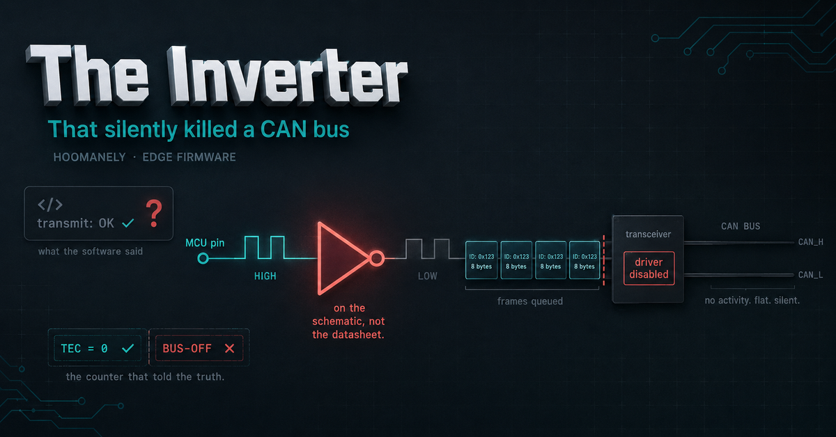
The hub board inside our feeding station reports air quality, light and motion to the rest of the device over a CAN bus. The firmware queued a frame. The controller accepted it. And nothing — nothing at all — appeared on the wire.
There was no error code to chase, no exception, no failed return value. Every layer the firmware could see reported success. The transmit path was working exactly as written, and the data was going nowhere.
The cause wasn't in the firmware's logic at all. It was a single component sitting on the schematic between a microcontroller pin and the chip it drives — a component the datasheet had no reason to mention, and that the code had therefore never accounted for. This is the story of finding it, proving it on the bench, and the one-line pattern that stops it from ever mattering again.
The Problem: A Transmit That Isn't
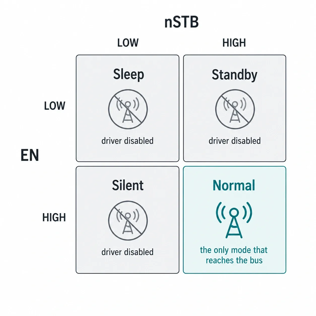
Between a microcontroller's CAN controller and the physical wires sits a transceiver — the analogue muscle that turns logic levels into differential signalling. It isn't a passive buffer. It has modes, selected by a couple of GPIO pins, and only one of them actually enables the transmit driver.
That creates a uniquely nasty failure. The controller inside the microcontroller is perfectly happy: it accepts your frame, arbitrates, and starts clocking bits out toward the transceiver. If the transceiver is sitting in a receive-only or low-power mode, those bits stop there. Nothing reaches the bus, nothing comes back, and the API you called returned success.
This is the worst class of bug in embedded work: not a crash, but a confident silence. Everything you can observe from software says the system is healthy.
The Trap: The Datasheet Isn't the Whole Truth
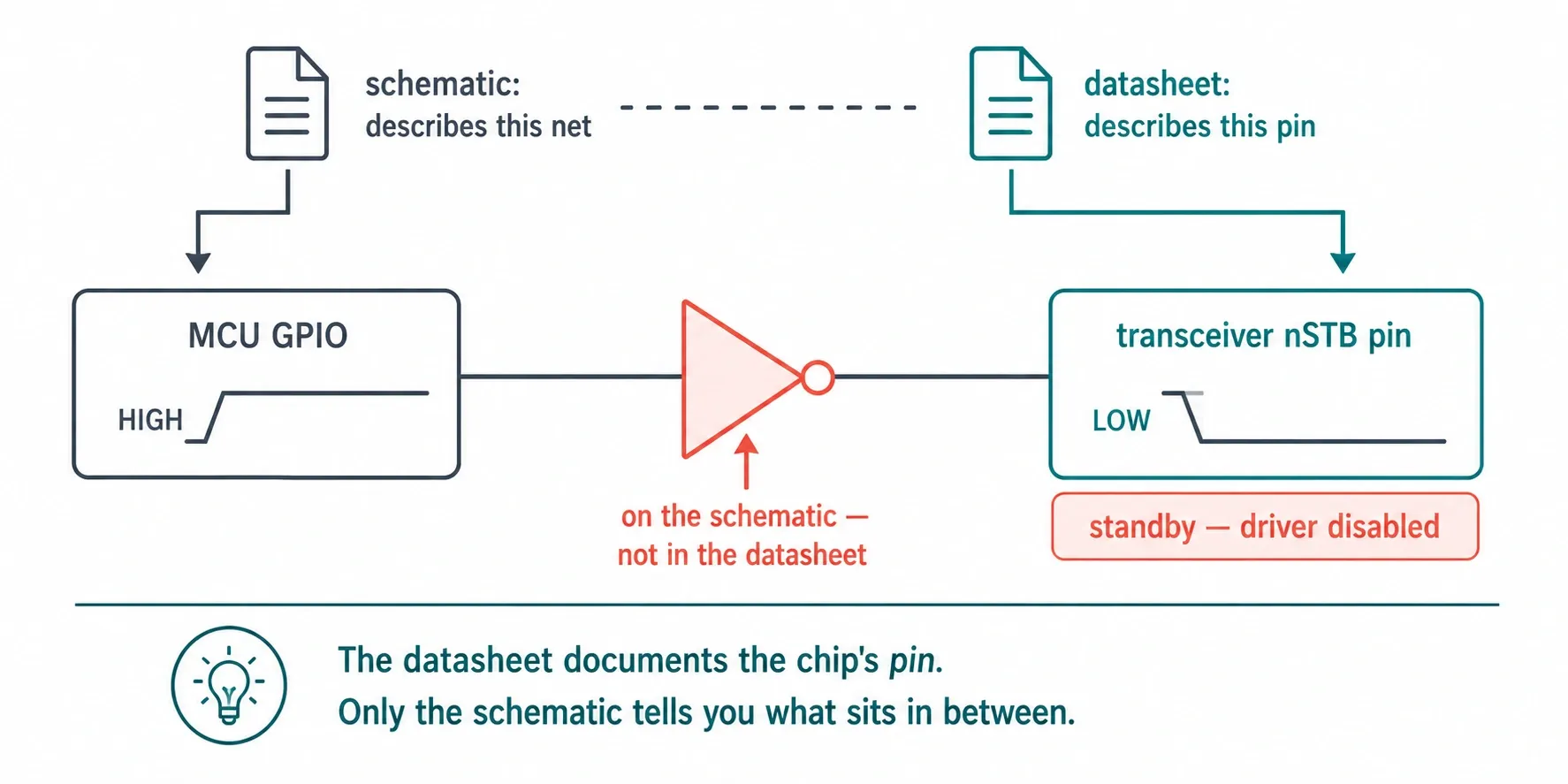
The transceiver's standby pin is active-low — its name literally carries the leading "n" that signals inversion. Drive it low and the device goes to standby; drive it high and the driver is enabled. Read the datasheet and the correct polarity is unambiguous.
The problem is that the datasheet describes the chip's pin, not your board's net. On this board there is an inverter physically sitting between the microcontroller's output and that pin. So the signal the firmware controls has the exact opposite meaning to the one the datasheet documents:
47	    /* DB board schematic: PB12 → "CAN_STB" net (active-HIGH = standby).
...
49	     *   PB12 HIGH → inverter → nSTB LOW → Standby (driver disabled)
50	     *   PB12 LOW  → inverter → nSTB HIGH → Normal  (driver enabled)
(Line 48, which names the specific part, omitted.)
Write the "obviously correct" value from the datasheet and you have just put the transceiver into standby with its driver disabled — while your code, and every log line it produces, insists it configured normal mode.
The Evidence: Proving It, Not Reasoning About It
The part of this I most admire is that the conclusion wasn't argued from the schematic — it was measured, and the measurement is recorded permanently in the code:
51	     * Evidence: old firmware (PB12=LOW for Normal) shows TEC=0 (ACKed);
52	     *           PB12=HIGH for Normal gives permanent bus-off (no ACK).
That single comment is a complete experiment. TEC is the transmit error counter, a register the CAN controller maintains itself. Every successfully acknowledged frame nudges it down; every failed transmission pushes it up, and if it runs away the controller takes itself off the bus entirely — the bus-off state.
So the two readings are decisive in opposite directions. A transmit error counter sitting at zero can only mean some other node on the bus acknowledged the frames — proof that the driver really was enabled and bits really did reach the wire. Permanent bus-off with no acknowledgement is proof of the reverse: the frames were never seen by anyone.
The controller was telling the truth the whole time, in a register nobody was reading. Silent failures usually are visible somewhere — the skill is knowing which counter to look at.
The Fix: Invert Once, at the Boundary
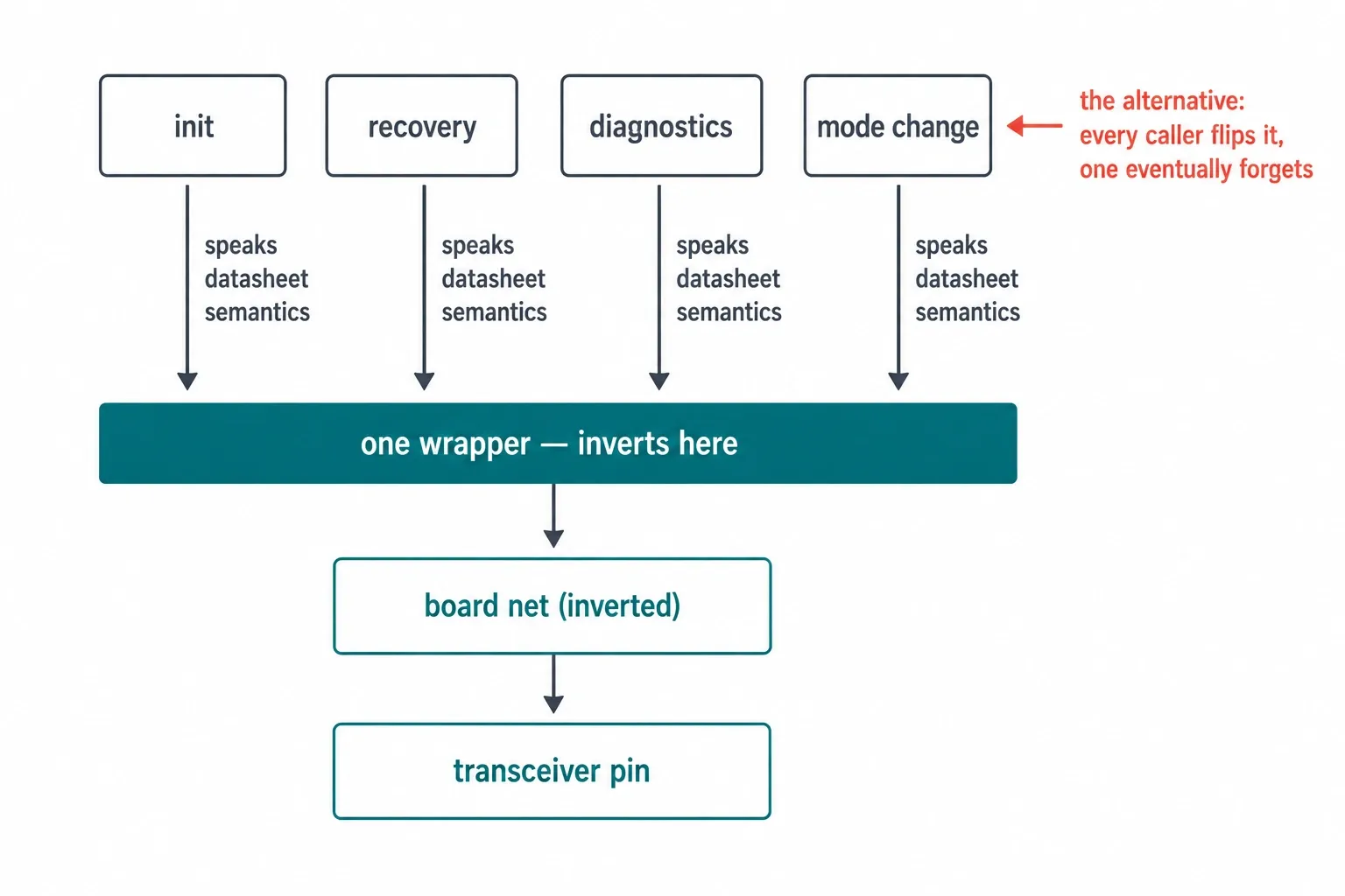
The tempting fix is to flip the polarity everywhere the pin is set, which spreads a board-specific quirk across the whole driver and guarantees someone eventually gets one site wrong. The actual fix confines the weirdness to a single function:
54	     * so its polarity is opposite.  This wrapper inverts the caller's
55	     * intent so the rest of the code can use nSTB semantics. */
56	    HAL_GPIO_WritePin(CAN_STB_GPIO_Port, CAN_STB_Pin,
57	                      (s == GPIO_PIN_SET) ? GPIO_PIN_RESET : GPIO_PIN_SET);
One ternary, in one wrapper. Above that line, every caller reasons in the chip's native semantics — the ones the datasheet describes and every engineer already has in their head. Below it, the board's inverter is absorbed and never thought about again.
The same discipline is applied in reverse when reading the mode back, so a query returns the true state at the chip rather than the raw level on the board net:
105	    GPIO_PinState en       = HAL_GPIO_ReadPin(CAN_EN_GPIO_Port,  CAN_EN_Pin);
106	    GPIO_PinState stb_raw  = HAL_GPIO_ReadPin(CAN_STB_GPIO_Port, CAN_STB_Pin);
107
108	    /* DB board has an inverter: PB12 reads the opposite of actual nSTB.
...
110	    GPIO_PinState nstb = (stb_raw == GPIO_PIN_SET) ? GPIO_PIN_RESET : GPIO_PIN_SET;
That symmetry matters more than it looks. A wrapper that inverts on write but not on read produces something worse than the original bug: a diagnostic function that confidently reports the opposite of reality.
The Wider Hazard: Same Chip, Opposite Polarity
Here is the part that turns a board bug into a portability lesson. A sibling board in the same product family uses the same transceiver wired directly, with no inverter in the path. Its correct pin values are therefore the exact reverse of this one's.
Two boards, one product family, identical-looking driver code, and contradictory pin semantics. Copy a working driver from one to the other — the most natural thing in the world to do — and it compiles cleanly, runs cleanly, logs cleanly, and transmits nothing.
That's why the reasoning lives in a comment rather than in someone's memory. The next engineer to port this file gets the trap and the evidence handed to them.
Everything Else the Transceiver Demands
The polarity was the headline, but the mode machine around it encodes several other rules worth stating plainly. Only one of the four modes actually permits transmission, and the code says so in as many words:
88	            /* EN=HIGH, nSTB=HIGH — Table 9-4: Normal (driver + receiver enabled)
89	             * This is the ONLY mode that enables the CAN bus driver for TX. */
90	            _en_set(GPIO_PIN_SET);
91	            _stb_set(GPIO_PIN_SET);
92	            break;
Mode changes also aren't instantaneous — the hardware needs time to settle, and the code deliberately spends far more than the datasheet's worst case rather than racing it:
98	    /* Mandatory settling time: datasheet t_moch up to 50 µs, use 10 ms */
99	    HAL_Delay(10);
And the fault line is open-drain and pulled up, so a low level is the alarm — another polarity that reads backwards to the uninitiated:
124	    /* nFAULT is open-drain, pulled up. LOW = fault asserted. */
125	    return (HAL_GPIO_ReadPin(nFAULT_GPIO_Port, nFAULT_Pin) == GPIO_PIN_RESET);
The Results
Once the polarity was corrected at the wrapper, the bus came up and stayed up: frames acknowledged, the transmit error counter resting at zero, no spurious bus-off. The sensor board's readings began arriving at the rest of the device exactly as the code had always claimed they were.
What made the fix durable was not the ternary but everything written around it. The truth table, the bench evidence, the note about the sibling board's opposite wiring, and the symmetric inversion on read-back mean the next person to touch this driver inherits the whole investigation rather than repeating it. A comment that records how you know is worth several that record what you did.
Why It Matters at Hoomanely
Hoomanely is reinventing healthcare for pets — replacing reactive, imprecise care with continuous, clinical-grade monitoring that catches problems early. Our devices form a Physical Intelligence ecosystem: sensors fused at the edge, feeding the Biosense AI Engine that turns raw signals into personalized, preventive insights.
Fusion only works if every sensor's data actually arrives. A board that silently stops transmitting doesn't announce itself as broken — it just produces a device that looks healthy while quietly contributing nothing, which is precisely the failure mode our whole reliability effort exists to eliminate.
Chasing a bug like this to the schematic, proving it with a hardware counter, and then writing the evidence down is the unglamorous work that makes continuous monitoring trustworthy. A pet's health record is only as good as the least reliable link carrying it.
Key Takeaways
- The schematic is part of your API. A datasheet describes the chip's pin; only the schematic tells you what components sit between it and your GPIO.
- Beware the transmit that isn't. A controller will happily accept frames that a mis-configured transceiver never puts on the wire — success at every layer you can see.
- Let the hardware's own counters testify. A transmit error counter at zero proves someone acknowledged you; permanent bus-off proves nobody did. Measure, don't reason.
- Absorb board quirks at a single boundary. One inverting wrapper keeps every caller speaking the datasheet's language — and invert symmetrically on read, or your diagnostics will lie.
- Write down how you know. Sibling boards with the same chip can need opposite pin values; a comment carrying the evidence is what stops the next port from failing silently.
Author's Note
This lives in the CAN driver on the sensor hub board inside Hoomanely's Everbowl. It's a handful of lines that do almost nothing — set two pins, wait ten milliseconds — and getting them wrong made an entire subsystem disappear without a single error message. My favourite thing in the file isn't the fix; it's the comment recording the two counter readings that proved which way round the world actually was.