CM4 Configuration Playbook

Hoomanely is a deep-tech hardware startup building intelligent IoT systems designed to be reliable, predictable, and humane in their interaction with users. Our engineering philosophy focuses on robust embedded design, modular hardware pipelines, and rapid prototyping without sacrificing stability.
In our early hardware development cycles, the Raspberry Pi Compute Module 4 (CM4) played a foundational role. Its flexible IO routing, Linux ecosystem, predictable bootloader, and Linux-level configurability made it an excellent reference platform. While our custom SOMs evolved later, the CM4 shaped much of Hoomanely’s approach to kernel bring-up, device-tree layering, and recovery-first embedded pipelines.
Introduction
The Raspberry Pi Compute Module 4 (CM4) provides the power of a full Linux computer with the flexibility of a bare compute module. This makes it ideal for embedded systems — but also significantly more complex than the Raspberry Pi 4 SBC. During prototyping at Hoomanely, we relied heavily on the CM4 to validate carrier boards, sensors, RF modules, and power architectures.
This configuration playbook is a comprehensive, technically accurate guide to understanding how the CM4 boots, how the kernel interacts with hardware, and how the device tree defines the system layout. It distills thousands of hours of engineering effort into a predictable, production-grade workflow.
The three control layers that define CM4 behavior are:
- EEPROM Bootloader & Boot Modes
- Kernel Configuration & Driver Availability
- Device Tree & Hardware Description
Understanding these three layers is essential before moving toward custom SOM development or designing production carrier boards.
1. Why CM4 Configuration Is Complex
Unlike a consumer Raspberry Pi board:
- The CM4 does not assume default hardware routing.
- Your carrier board defines power, USB topology, SDIO, PCIe, and GPIO usage.
- Kernel modules are not automatically loaded unless DT describes the hardware.
- Boot behavior depends on EEPROM configuration, not SD card presence.
- Hardware functions require explicit device tree muxing.
During prototyping at Hoomanely, each new hardware revision required:
- new device-tree overlays,
- kernel module tuning,
- EEPROM configuration alignment,
- and a robust recovery pipeline.
The CM4 makes no assumptions - which is exactly why it's powerful for embedded systems.
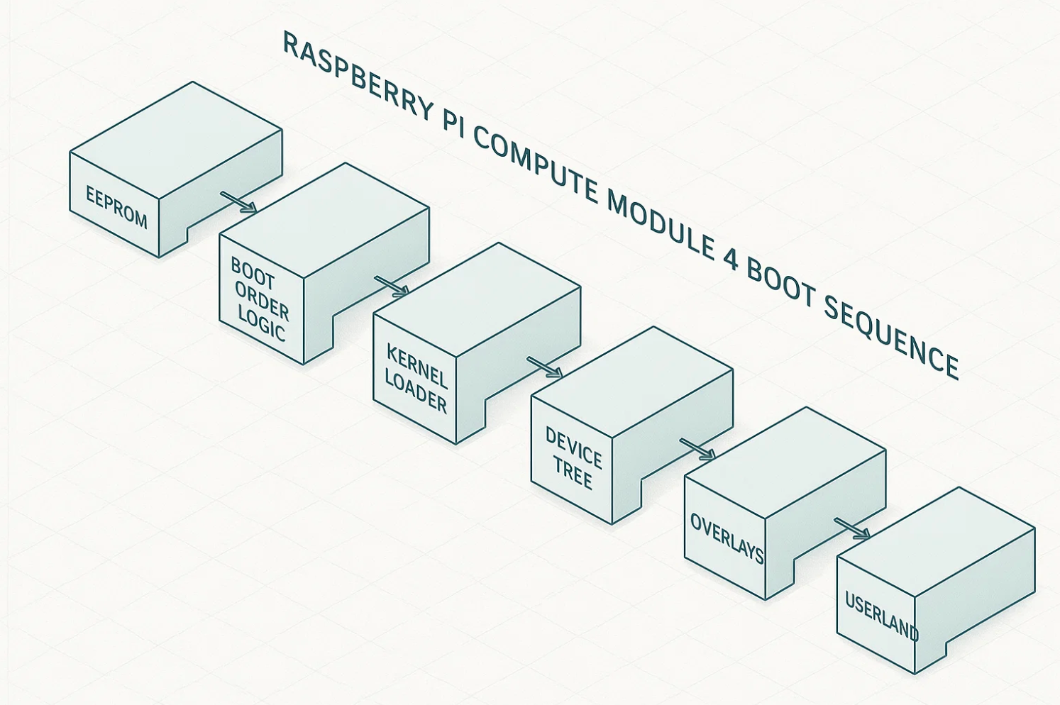
2. CM4 Bootloader & Boot Modes (EEPROM)
Every CM4 contains an onboard SPI flash that stores the EEPROM bootloader. This determines:
- the boot sequence,
- PCIe enablement,
- early serial console,
- network boot behavior,
- USB boot behavior.
Checking the EEPROM Versionsudo rpi-eeprom-update
sudo rpi-eeprom-config
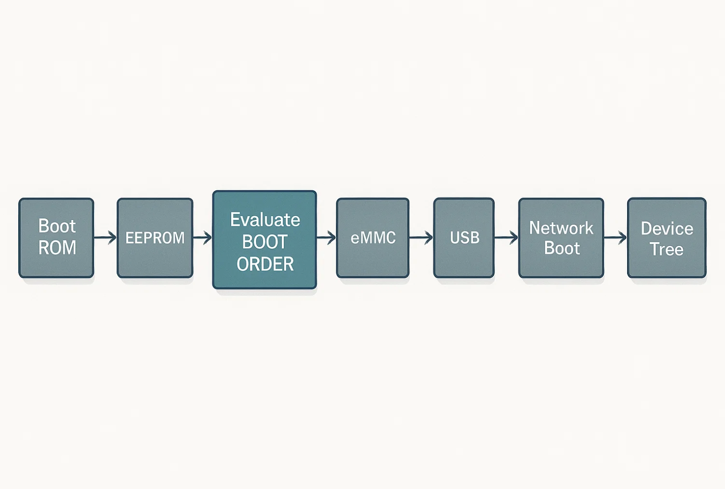
BOOT_ORDER Breakdown
The EEPROM uses a hex sequence that defines boot priority:
| Hex | Boot Source |
|---|---|
1 | SD Card |
2 | Network Boot (PXE) |
4 | eMMC |
5 | USB Mass Storage |
f | Stop |
Example:
BOOT_ORDER=0xf2541
This means:
Try SD → Try eMMC → Try USB → Try Network → Stop
This order works well for prototyping because you can experiment with SD/USB boot while still validating eMMC bring-up.
Important EEPROM Properties
| Key | Technical Significance |
|---|---|
PCIE_PROBE=1 | Enables PCIe root complex early in boot (required for NVMe or PCIe modems). |
UART_ENABLE=1 | Enables UART0 debug logs from the bootloader. |
USB_MSD_EXCLUDE=1 | Disables USB MSD boot for production hardening. |
WAKE_ON_GPIO=1 | Enables wake-from-sleep on GPIO transitions. |
Recovery Mode via nRPIBOOT
Pulling the nRPIBOOT pin low forces CM4 into USB device boot mode, allowing recovery even if eMMC is corrupted.
This was extremely useful during Hoomanely bring-up phases when testing unstable kernels or device trees.
3. Kernel Configuration: Drivers, DMA, PCIe & Debugging
The CM4 uses the same BCM2711 SoC as the Pi 4, and kernel support is delivered through the Raspberry Pi downstream Linux kernel.
Why Kernel Config Matters
- PCIe requires specific drivers & MSI support.
- DMA engines must be enabled for high-speed devices.
- I2C/SPI/UART controllers require explicit configuration.
- Filesystem choices affect system lifetime & reliability.
Key Kernel Flags for CM4-Based Systems
PCIe Subsystem
CONFIG_PCIE_BRCMSTB=y
CONFIG_PCI_MSI=y
MSI is crucial for stable interrupt delivery for PCIe devices.
DMA Engine
CONFIG_DMA_BCM2711=y
Required for camera pipelines, high-speed SPI sensors, and internal SoC functions.
USB Host and Device Support
CONFIG_USB_XHCI_HCD=y
CONFIG_USB_DWC2=y
XHCI is required for USB 3.0 on CM4.
GPIO & Pin Muxing
CONFIG_PINCTRL_BCM2835=y
CONFIG_GPIO_SYSFS=y
OverlayFS & SquashFSCONFIG_OVERLAY_FS=y
CONFIG_SQUASHFS=y
Useful Diagnostic Commands
dmesg | grep -iE "pcie|brcm|mmc|dma|xhci"
This allowed us to quickly identify:
- PCIe enumeration failures
- WiFi firmware load errors
- Unsupported kernel modules
- Bad DMA configurations
4. Device Tree (DTS): Hardware Description Layer
The device tree defines the exact hardware layout of your carrier board.
If DTS is wrong, the kernel cannot see your hardware, even if correctly wired.
Extract the live device tree
sudo dtc -I fs -O dts /proc/device-tree > running.dts
Common DTS Tasks for CM4 Prototyping
Enabling UART4dtoverlay=uart4
Disabling onboard WiFi/Bluetooth
Useful when using external modules.
dtoverlay=disable-wifidtoverlay=disable-bt
Custom I²C Sensor Example
    compatible = "bosch,bme688";
    reg = <0x68>;
    status = "okay";
    interrupt-parent = <&gpio>;
    interrupts = <23 IRQ_TYPE_EDGE_FALLING>;
};```
GPIO Pin Muxing Example
    hm_pins: custom_pinmux {
        brcm,pins = <17 18>;
        brcm,function = <BCM2835_FSEL_ALT0>;
        brcm,pull = <0>;
    };
};
Compile Overlay
dtc -I dts -O dtb custom_overlay.dts -o custom_overlay.dtbo
Hoomanely’s Device Tree Layering Strategy
Because carrier-board revisions changed weekly:
- We built modular DTS fragments.
- Each hardware revision had a DT manifest.
- Boot scripts validated DT correctness.
This avoided silent hardware misconfiguration during rapid prototyping.
5. CM4 Bring-Up & Recovery Pipeline
Embedded systems need a recovery-first design.
The CM4 enables multiple recovery layers.
Stage 1 — Soft Recovery
Enter rescue mode:
sudo systemctl isolate rescue.target
Reset broken config.txt:
sudo cp /boot/config.txt.backup /boot/config.txt
Re-install kernel:
sudo apt reinstall raspberrypi-kernel
Stage 2 — EEPROM Recovery via USB Boot
- Pull nRPIBOOT low
- Connect CM4 to a host via USB
- Run:
sudo rpiboot
This exposes eMMC as a USB mass-storage device.
This saved numerous CM4 boards during Hoomanely kernel experiments.
Stage 3 - Full Factory Reflash
We maintain:
- Signed base OS image
- Validated kernel build
- DTS bundle
- Automated bring-up tests
Flash using:
rpi-imager --cli --image factory.img --device /dev/sdX
or via rpiboot for eMMC variants.
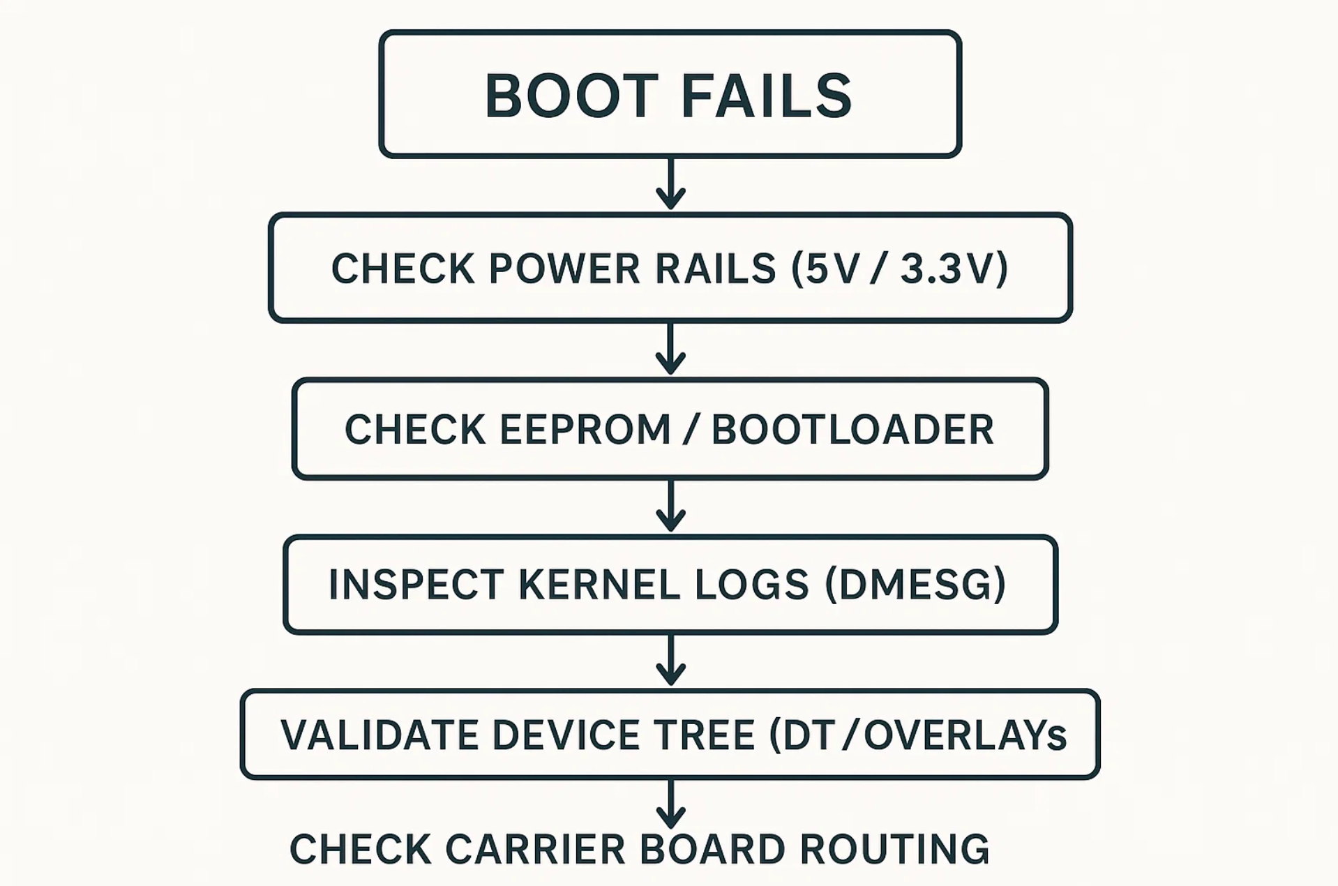
6. Troubleshooting CM4: Field-Proven Methods
PCIe Not Enumerating
Check:
dmesg | grep -i pcie
Verify:
PCIE_PROBE=1- REFCLK routing & AC-coupling on carrier board
- Kernel MSI support
- Device tree has
"pci@7d500000"
WiFi Not Working
Check firmware load:dmesg | grep brcmfmac
Common issues:
- Missing RF antenna enable GPIO
- Bad DT property
brcm,sdio-drive-strength - 2.4 GHz antenna mismatch
SD/eMMC Not Detected
Check:
dmesg | grep -i mmc
Common issues:
- Wrong bus width (
bus-width = <4>missing) - Missing 100k pull-ups on CMD/DAT lines
- Incorrect SDIO voltage domain
GPIO Not Behaving
Check real-time muxing:raspi-gpio get
Ensure:
- No overlapping DTS functions
- Correct pull-up/down settings
- No alternate functions blocking GPIO
7. Why CM4 Was Ideal for Hoomanely’s Prototyping Phase
During Hoomanely’s hardware discovery and iteration phases, we needed a compute platform that could:
- expose high-speed buses,
- allow fast device-tree iteration,
- provide stable Linux kernel behavior,
- support complex sensor arrays,
- validate RF, PCIe, SDIO, and USB subsystems,
- and recover quickly from experimental configurations.
The CM4 delivered all of this with:
- predictable EEPROM behavior,
- deep kernel configurability,
- flexible muxing capability,
- and a fast bring-up cycle.
It allowed us to evolve our hardware confidently before moving to custom hardware architectures.
8. Key Takeaways
- The CM4 is powerful because it gives ultimate control, but that means engineers must understand EEPROM, kernel, and DTS layers.
- Bootloader configurations define boot priority, PCIe enablement, debug access, and rescue paths.
- Kernel flags determine driver availability, DMA paths, and high-speed interface stability.
- Device tree correctness is essential — with wrong DT, hardware becomes invisible.
- Recovery-first design prevents prototype downtime.
- CM4 is an excellent reference compute module for rapidly evolving embedded teams like Hoomanely


