Designing a Board That Can Survive Rework Multiple Times
Rework is not an exception in hardware development.
It is part of the process.
Boards are probed, components are replaced, connectors are re-soldered, tracks are modified, and sometimes entire sections are rebuilt — all before the design reaches stability.
Yet most boards are not designed with rework in mind.
They are designed to be manufactured once — cleanly, perfectly, and permanently.
And that mismatch creates problems.
Pads lift.
Traces peel.
Thermal stress damages nearby components.
Debugging becomes harder after every rework cycle.
At Hoomanely, we treat rework as a design input, not a post-production inconvenience.
Because a board that survives rework doesn’t just last longer —
it accelerates development, reduces cost, and improves reliability across the entire lifecycle.
The Problem: Boards That Degrade with Every Touch
A typical PCB is optimised for:
- compact routing
- minimal spacing
- cost efficiency
- automated assembly
But during rework:
- solder joints are heated repeatedly
- pads are mechanically stressed
- nearby components are exposed to heat
- copper adhesion is tested beyond its limits
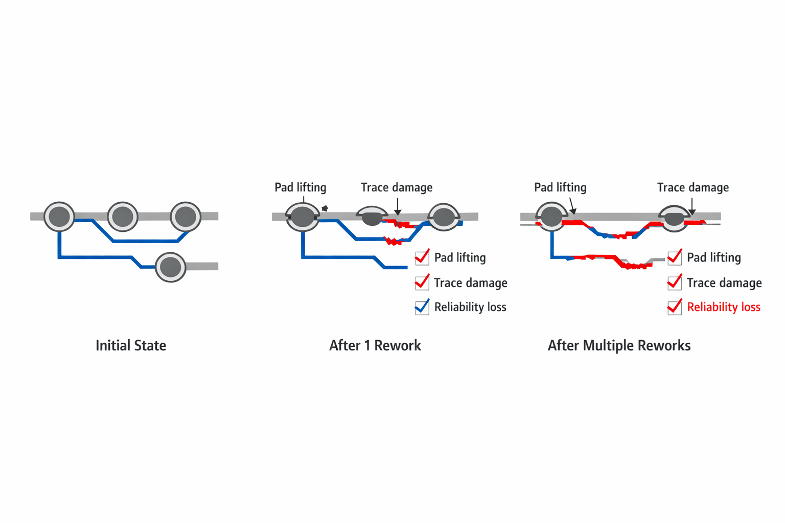
Without deliberate design support, each rework cycle introduces:
- weakened pads
- micro-cracks in traces
- increased electrical resistance
- intermittent faults
The board may still “work,” but it becomes unreliable.
And debugging an unreliable board is one of the most time-consuming problems in hardware.
Designing Pads That Don’t Lift
Pad lifting is one of the most common failures during rework.
It happens when:
- the copper pad detaches from the substrate
- repeated heating weakens adhesion
- mechanical force pulls the pad during component removal
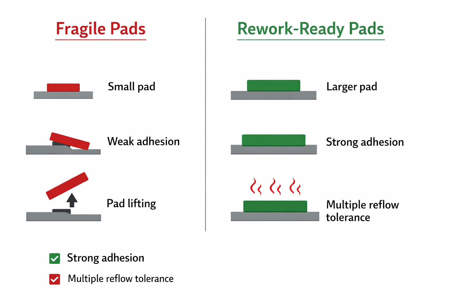
To prevent this, pad design must be intentional.
That means:
- sufficient pad size relative to component
- proper annular ring dimensions
- avoiding overly aggressive thermal reliefs
- ensuring strong copper-to-substrate bonding
In critical areas, we also:
- increase pad robustness slightly beyond minimum requirements
- avoid ultra-fine geometries where unnecessary
The goal is simple:
pads should tolerate multiple soldering cycles without degradation.
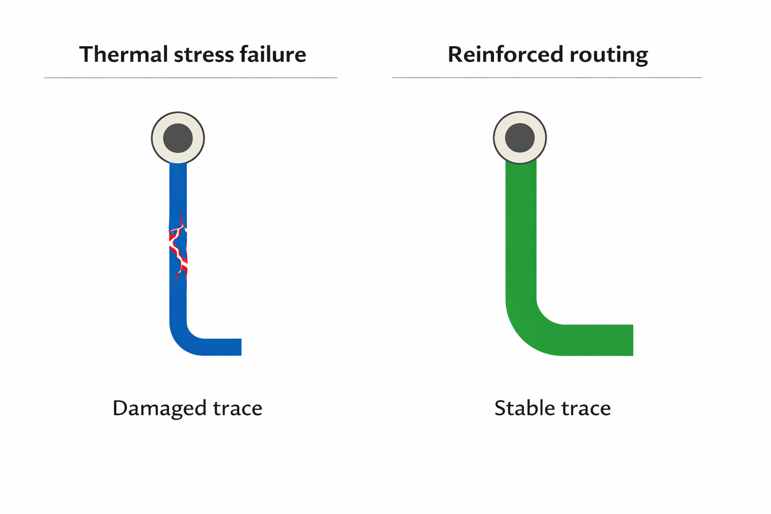
Trace Routing That Survives Heat and Stress
Traces connected to reworked components are vulnerable.
During rework:
- heat expands materials
- solder wicking can pull on traces
- mechanical movement stresses connections
If traces are too thin or poorly supported:
- they crack
- they delaminate
- they fail intermittently
So we design traces near rework-prone areas with:
- slightly increased width
- smooth transitions (no sharp corners)
- short, direct paths
- mechanical stability
This ensures that even after multiple thermal cycles, connectivity remains intact.
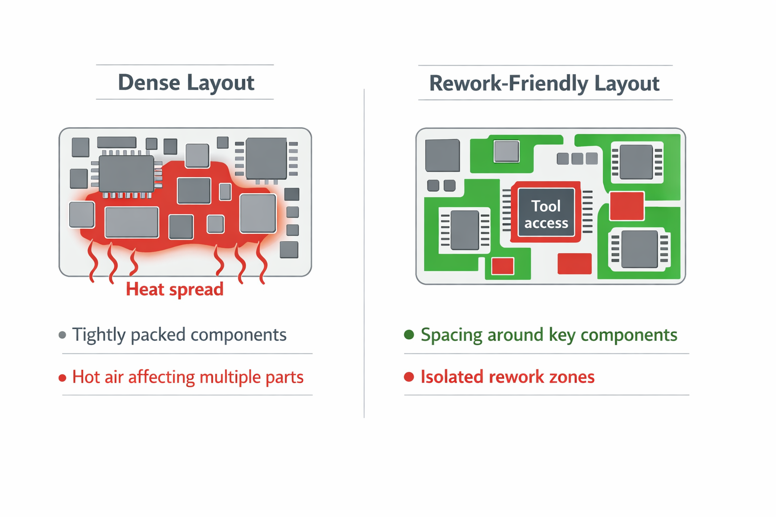
Component Spacing: Designing for Tools, Not Just Layout
Dense layouts look efficient.
But they make rework difficult.
- hot air affects adjacent components
- solder bridges form easily
- tweezers cannot access components cleanly
- inspection becomes harder
So we introduce intentional spacing in critical areas.
Not everywhere — only where it matters:
- around connectors
- near frequently replaced components
- around debug interfaces
- near power devices
This allows:
- precise heat application
- clean component removal
- reduced collateral damage
Rework is not just electrical.
It is physical.
And the board must respect that.
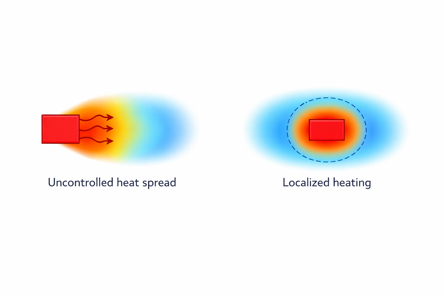
Thermal Design for Rework Conditions
Thermal behaviour during rework is very different from normal operation.
- heat is localised
- temperature gradients are steep
- nearby components experience unintended heating
Without planning, this causes:
- solder reflow in unintended areas
- component drift
- damage to sensitive parts
So we design thermal characteristics deliberately:
- controlled copper distribution around critical components
- balanced thermal relief for pads
- avoiding large copper pours directly attached to small pads (unless required)
This ensures:
- predictable heating
- faster rework cycles
- reduced thermal stress
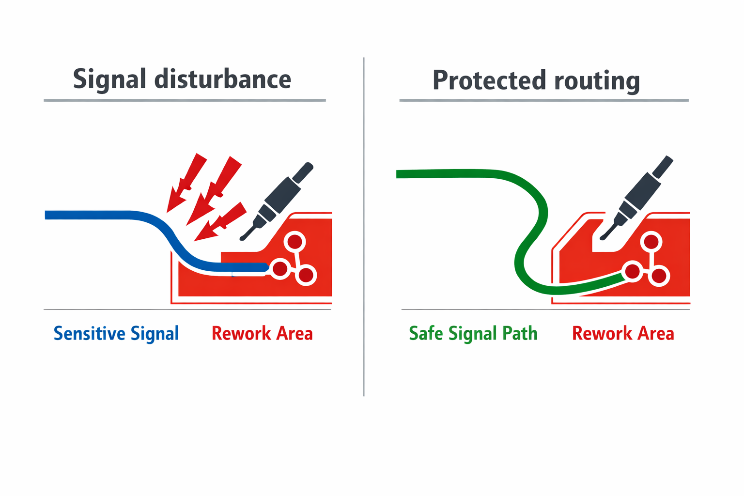
Protecting Critical Nets During Rework
Some signals cannot tolerate disturbance:
- high-speed lines
- sensitive analogue paths
- reference signals
Rework near these nets can introduce:
- impedance changes
- noise coupling
- signal degradation
So we isolate critical nets from rework zones:
- maintain distance from high-risk components
- avoid routing sensitive lines under rework-heavy areas
- use controlled reference planes
This ensures that rework does not silently degrade system performance.
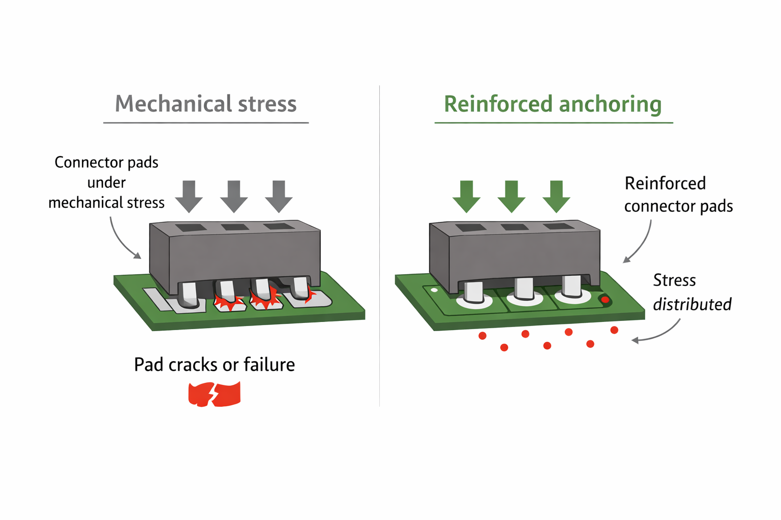
Designing Connectors for Repeated Handling
Connectors are frequently:
- plugged and unplugged
- re-soldered
- mechanically stressed
If not designed properly:
- pads crack
- solder joints weaken
- alignment shifts
We design connector interfaces with:
- strong mechanical anchoring
- sufficient pad support
- stress distribution through board area
In modular systems (like EverBowl-style architectures), this becomes even more important.
Because connectors define:
- system reliability
- serviceability
- long-term durability
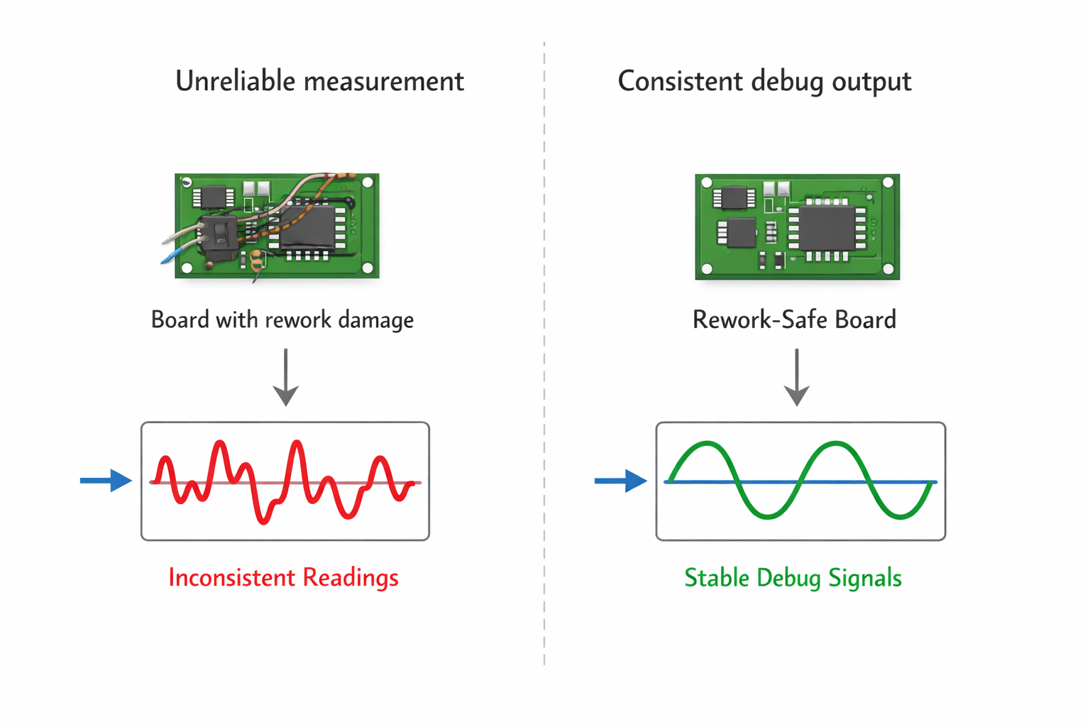
Making Debugging Reliable After Rework
One hidden problem with rework is loss of trust in the board.
After multiple changes:
- is the failure real?
- or is it caused by previous rework damage?
To avoid this, we ensure:
- debug points remain intact and accessible
- reference signals are stable
- power rails remain consistent
The board should behave predictably even after multiple interventions.
Because debugging should focus on the system — not on whether the board itself is compromised.
Practical Observations from EverBowl-Like Systems
In systems similar to EverBowl, rework happens across multiple iterations:
- sensor boards are swapped
- connectors are replaced
- power sections are tuned
- layouts evolve rapidly
We observed:
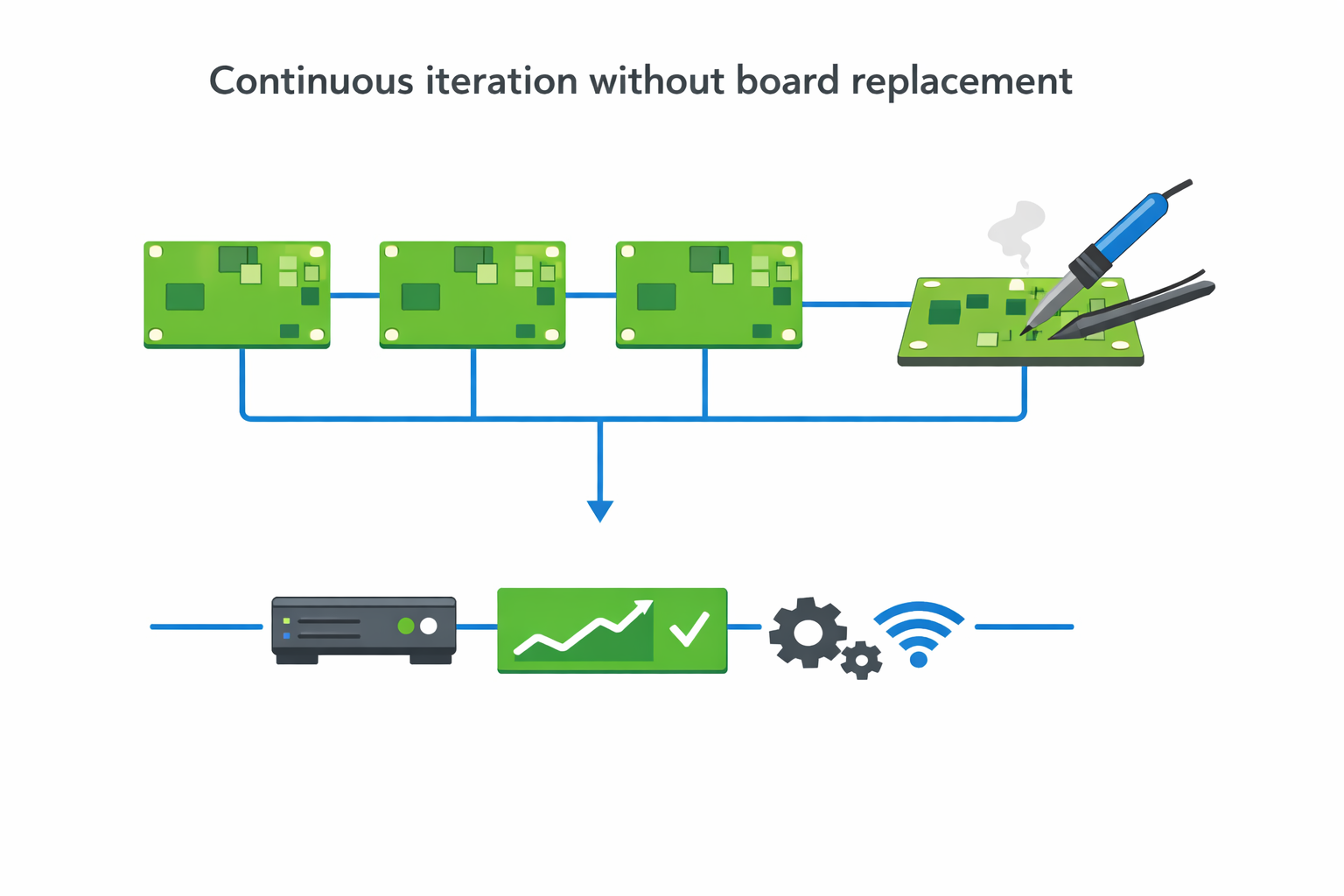
Boards Lasted Longer Across Iterations
Fewer boards needed replacement during development.
Debugging Became More Reliable
Engineers trusted measurements even after multiple rework cycles.
Faster Iteration Cycles
Less time spent repairing damage caused by previous fixes.
Reduced Cost Over Development
Fewer prototype rebuilds and replacements.
These improvements came from designing for rework — not reacting to it.
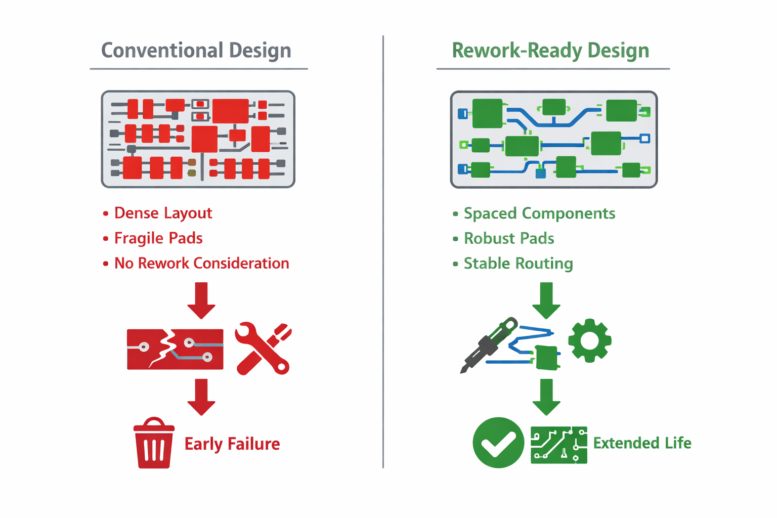
Conventional vs Structured Approach
Conventional approach:
- optimise for manufacturing
- minimal spacing
- fragile pads and traces
- rework considered temporary
Hoomanely approach:
- design for repeated intervention
- robust pads and traces
- intentional spacing
- stable behaviour across cycles
The difference is not visible in the schematic.
It becomes obvious during the third or fourth rework cycle —
when one board still works, and the other doesn’t.
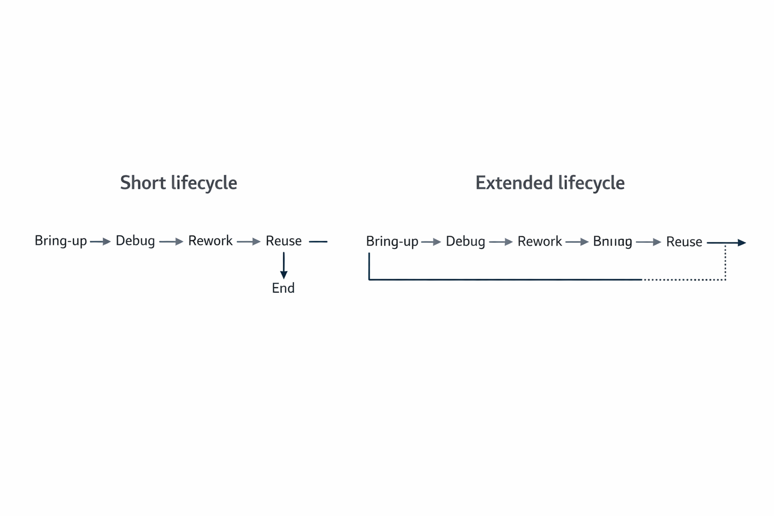
Designing for the Full Lifecycle
A board is not just manufactured once.
It goes through:
- bring-up
- debugging
- validation
- modification
- sometimes field repair
Each stage applies stress.
If the design only supports the first stage, it fails in the rest.
So we design for the full lifecycle:
- durability during rework
- stability after modification
- consistency across iterations
This ensures that the board remains a reliable platform — not a disposable artifact.
The Core Principle
A good PCB should not just work once.
It should continue to work even after being touched, modified, and reworked multiple times.
That requires:
- mechanical robustness
- thermal stability
- electrical integrity
All working together.
Final Thought
Rework is not a sign of failure.
It is a sign of progress.
But only if the board supports it.
At Hoomanely, we design boards that:
- tolerate repeated intervention
- maintain integrity across cycles
- support faster iteration
Because in real hardware development, the first version is never the final one.
And the boards that survive the journey are the ones that were designed for it from the beginning.