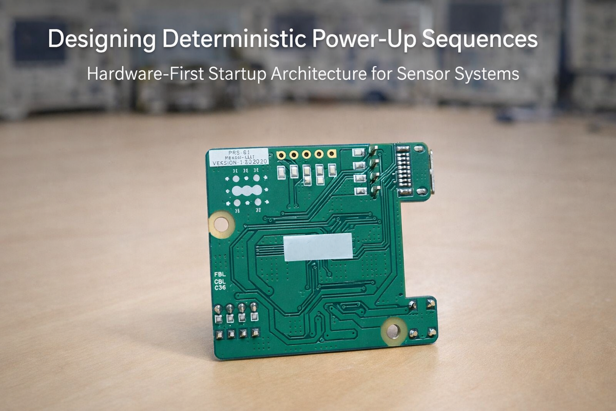
Designing a Power-Up Sequence That Works Before Firmware Exists
In embedded systems, we often talk about performance in terms of processing speed, sensor accuracy, or power efficiency.
But there is another moment that defines product quality long before any of those metrics matter:
The first 50 milliseconds after power is applied.
That moment determines whether your system boots cleanly, whether your sensors initialise correctly, whether your buses remain stable, and whether your firmware even gets a chance to run.
In multi-sensor architectures — especially those combining image sensors, proximity modules, mixed-voltage logic, and high-speed interfaces — power-up behaviour is not a background detail.
It is the foundation.
And it must work before firmware exists.
The Illusion of “It Boots Fine”
Many boards appear stable in development. You plug them in, they start, and everything looks normal.
But what you rarely see is:
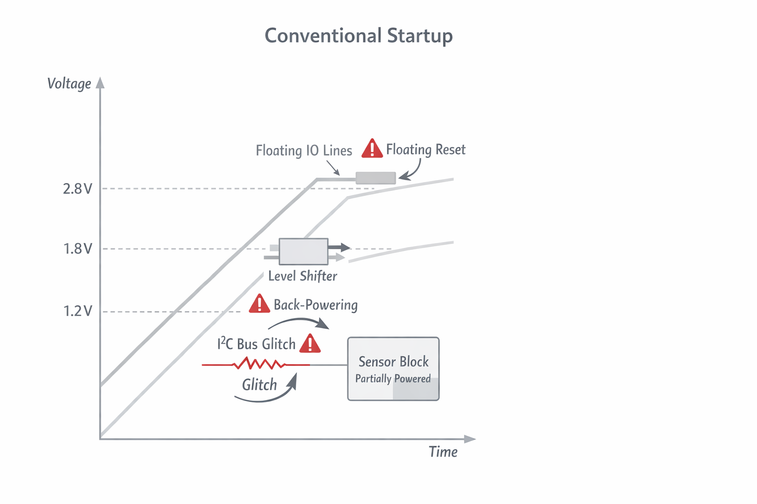
- Rails rising at different slopes.
- IO domains partially powered.
- Sensors latching undefined states.
- Buses glitching during ramp.
- Level shifters back-powering domains.
- Reset lines floating during brown transitions.
These do not always cause immediate failure.
They cause intermittent behaviour.
A camera that occasionally fails detection.
A proximity sensor that locks the I²C bus once every few hundred boots.
A startup that works on warm resets but fails during cold power application.
The system “mostly works.”
That is the most dangerous state.
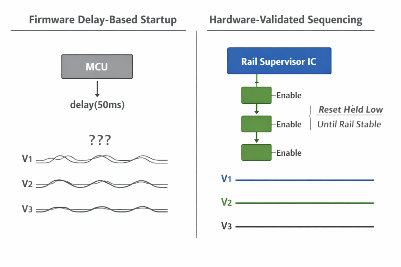
Why Firmware Delays Are Not Sequencing
A common solution looks like this:
Enable regulators → wait 50 ms → release reset → initialize sensors.
This approach assumes:
- Rails reached nominal voltage.
- Ripple has settled.
- Oscillators are stable.
- Downstream devices completed internal POR.
- No IO injection occurred during ramp.
But firmware delay is not voltage validation.
It is a guess.
In sensor-heavy systems, guessing is not deterministic design.
We moved sequencing into hardware.
Enforcing Rail Order in Hardware
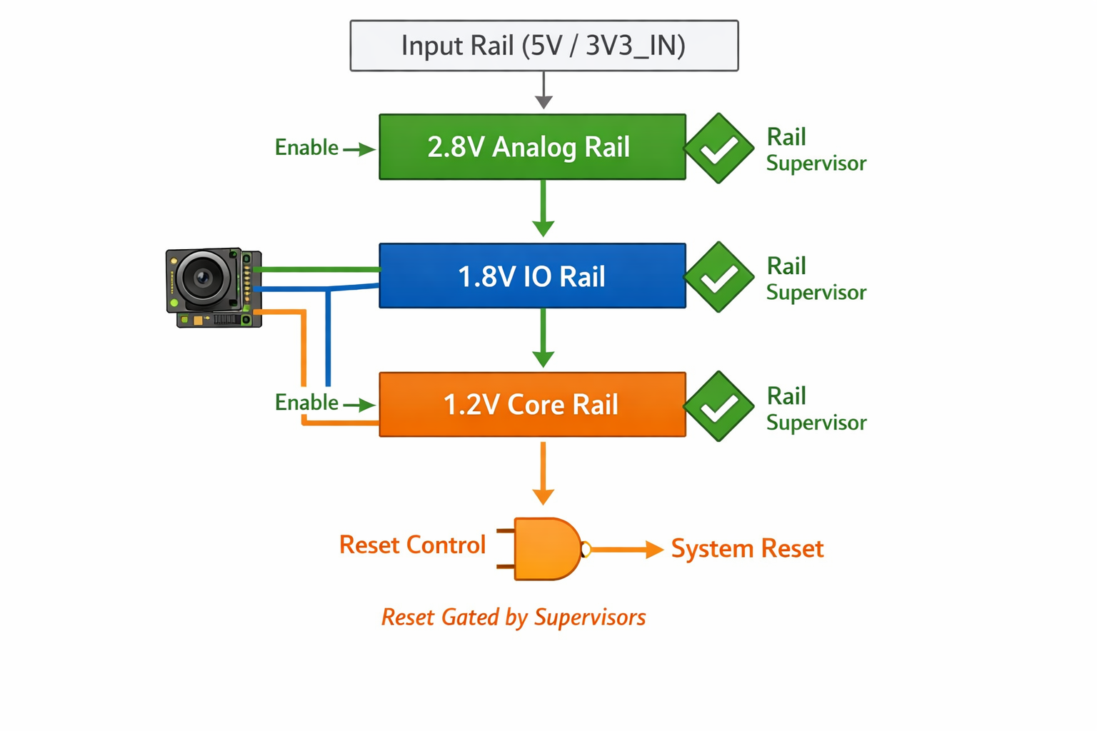
Our image sensor and associated peripherals require strict rail sequencing:
2.8V (Analog) → 1.8V (IO) → 1.2V (Core)
This is not arbitrary.
It is defined by the silicon architecture of the device.
Instead of relying on firmware, we implemented:
- Hierarchical regulator enable chaining.
- Dedicated power supervisor IC for rail validation.
- Reset gating based on rail stability.
- Controlled ramp slopes using proper decoupling layout.
The result:
No partial domain biasing.
No back-powering through IO pins.
No undefined analog states.
No statistical boot variance.
The system either boots correctly — or it does not enable at all.
That predictability matters.
Reset Is an Architecture, Not a GPIO
Power sequencing without reset discipline is incomplete.
In many conventional boards:
- MCU reset controls everything.
- Peripheral reset lines are loosely connected.
- Sensors rely on internal POR.
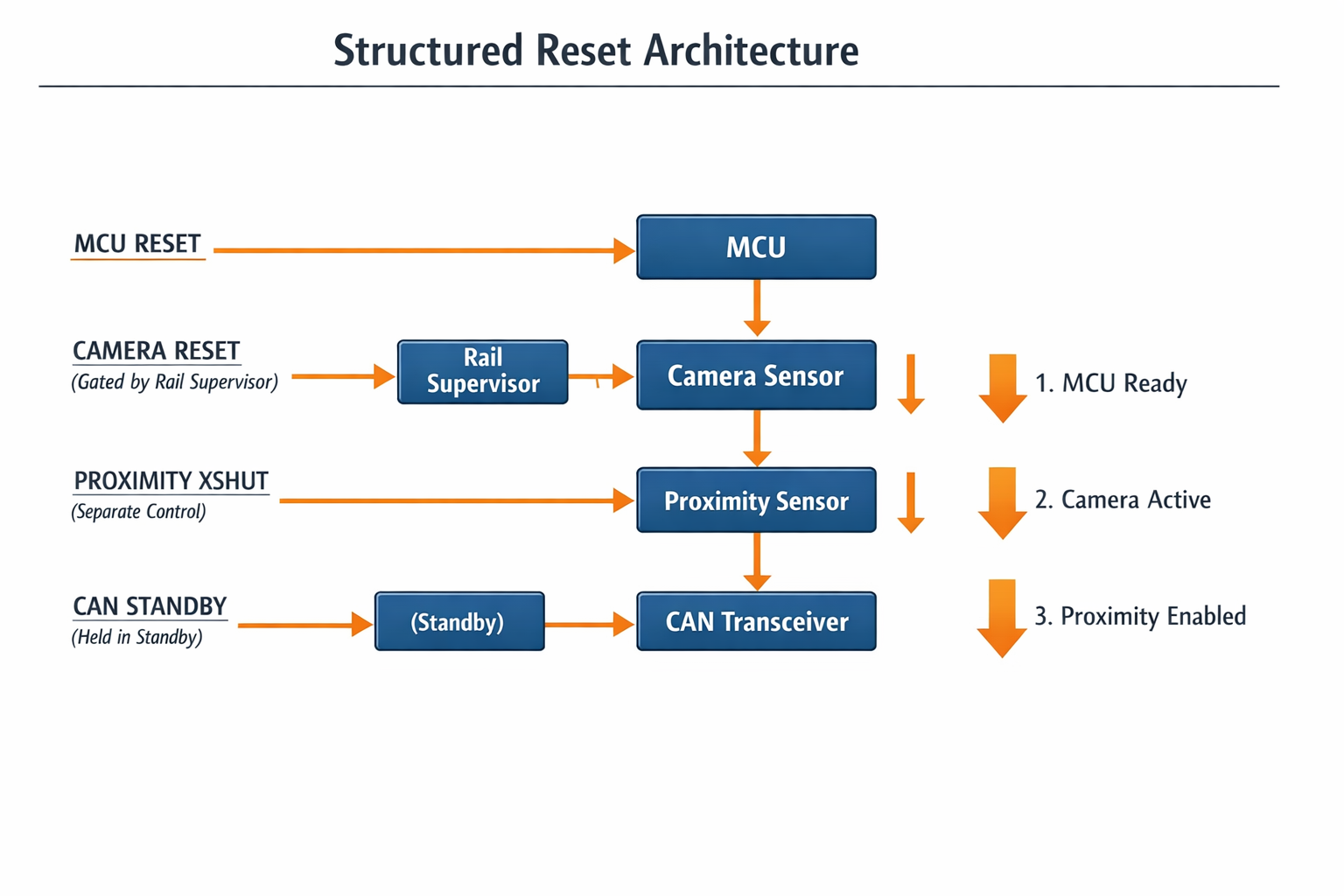
We separated reset domains deliberately:
- MCU reset independent from camera reset.
- Camera reset released only after rail validation.
- Proximity sensor shutdown controlled explicitly.
- Communication transceivers held in defined states during ramp.
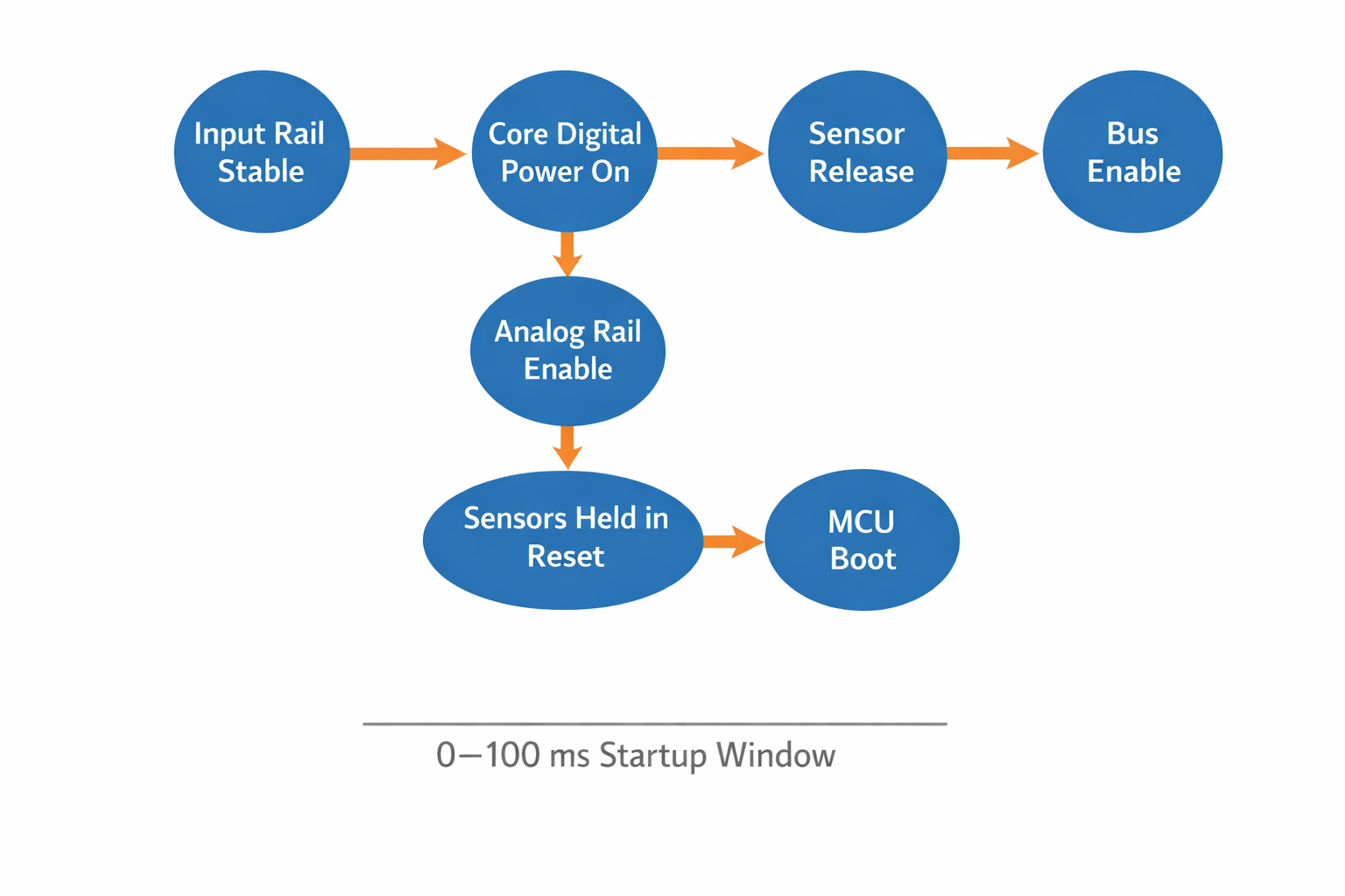
The sequence becomes structured:
- Input rail stabilizes.
- Core logic powers.
- Analog rails enable.
- Sensors remain held in reset.
- MCU boots.
- Firmware configures clocks and IO.
- Sensors released in controlled order.
- Buses enabled last.
There are no races.
Only defined transitions.
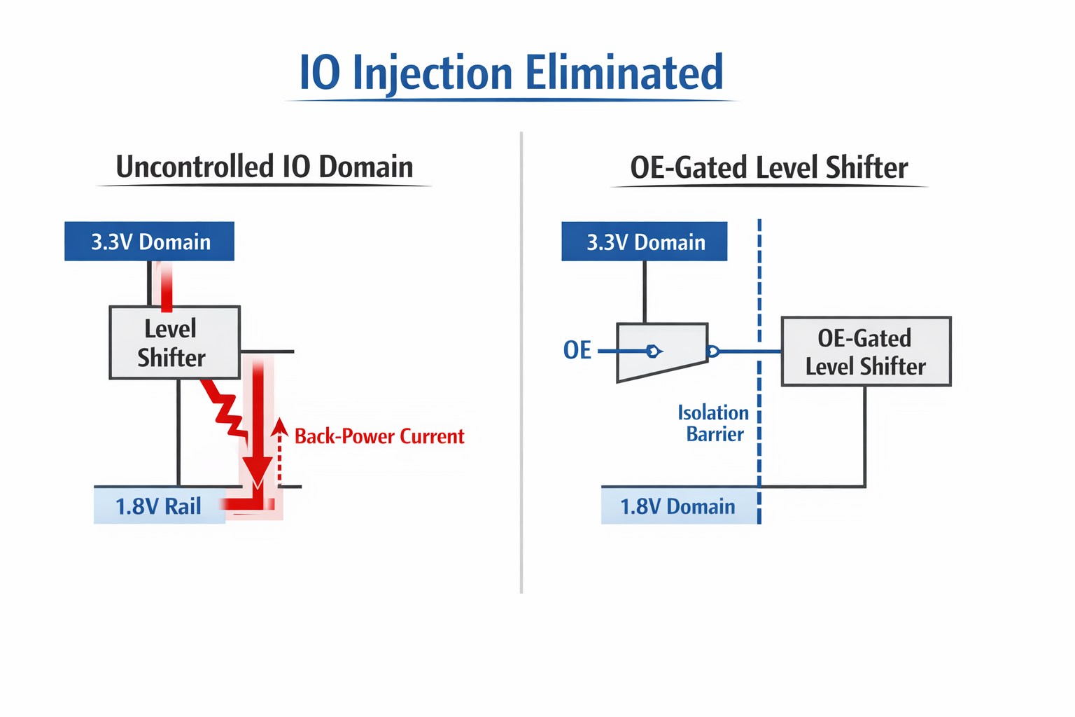
Eliminating Back-Powering and IO Injection
Mixed-voltage systems are vulnerable during ramp:
1.8V domains connected to 3.3V logic.
Level shifters bridging rails.
Open-drain buses with asymmetric pull-ups.
During uncontrolled startup, these can cause:
- IO injection currents.
- Phantom powering of sensor domains.
- Latch-up conditions.
- Increased long-term silicon stress.
We addressed this through:
- Direction-aware level shifting.
- OE gating tied to valid rails.
- Proper pull-down biasing on floating lines.
- Physical separation of analog and digital return paths.
- Explicit enable control of bus drivers.
The goal was not only functionality.
It was longevity.
What Changed After We Implemented Deterministic Sequencing
The improvements were not theoretical.
We observed measurable differences:
Boot Repeatability
Cold-start consistency became deterministic across voltage and temperature ranges.
Sensor Initialisation Stability
Camera and proximity sensor initialisation success became consistent under all startup conditions.
Bus Reliability
I²C lockups during ramp were eliminated.
Reduced Startup Current Overlap
Staggered rail activation reduced instantaneous inrush stacking between domains.
Cleaner EMI During Ramp
Simultaneous switching noise at power application was measurably lower.
None of these changes were visible in the product UI.
All of them were visible in long-term stability.
Why This Matters in Sensor-Driven Products
Digital-only systems tolerate sequencing sloppiness.
Sensor systems do not.
Image sensors contain:
- Analog bias circuits.
- PLLs.
- Reference generators.
- Mixed-signal IO pads.
Proximity modules contain:
- Precision timing blocks.
- Internal state machines.
- Interrupt generation logic.
Thermal imagers maintain:
- Calibration states.
- EEPROM-loaded correction parameters.
If these wake up in undefined voltage conditions, the system may appear alive — but not healthy.
We removed that ambiguity.
Designing for the First 100 Milliseconds
A stable system is defined not by runtime performance, but by its transition states.
We treat power-up as a state machine:
- Each rail has dependency.
- Each enable has ownership.
- Each reset has purpose.
- Each IO domain is protected.
If a rail fails to stabilise, downstream domains never release.
If a reset is asserted, no bus activity occurs prematurely.
The system does not rely on luck.
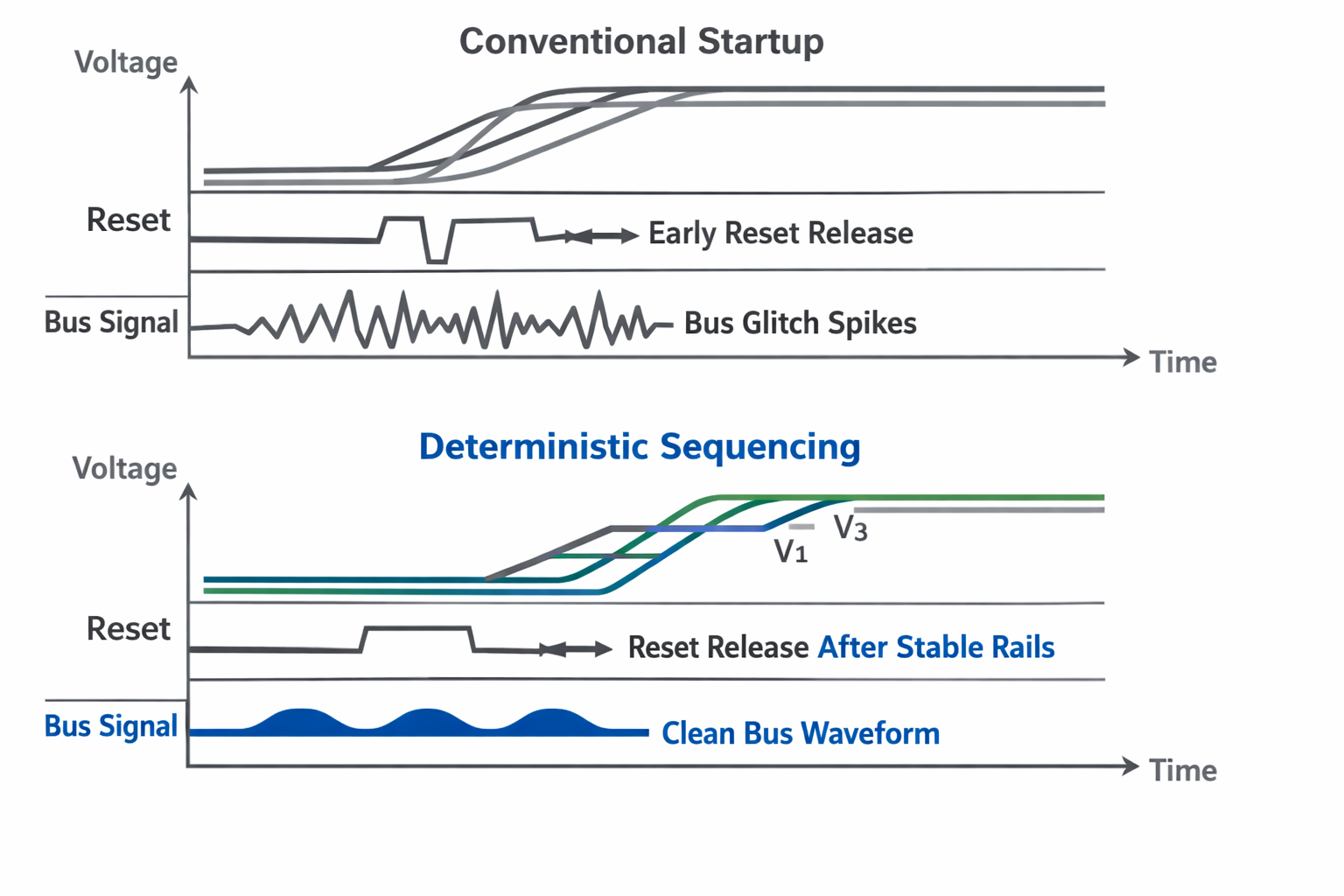
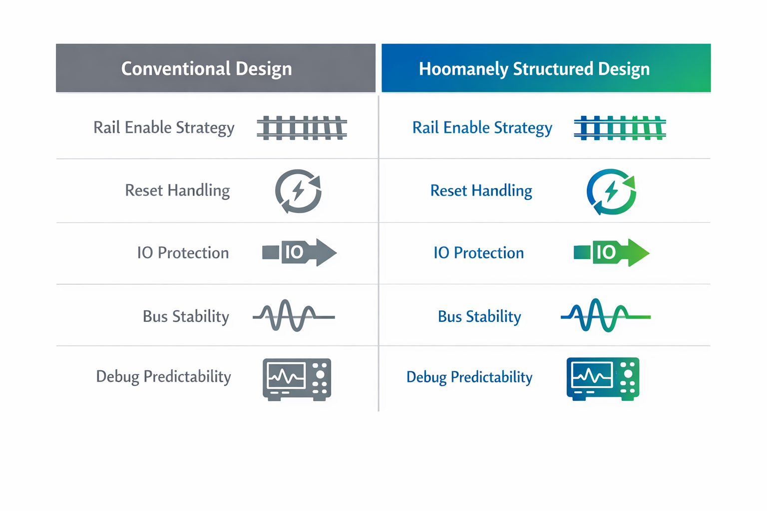
Conventional Startup vs Structured Startup
Conventional Design:
- All rails enabled together.
- Firmware waits.
- Sensors self-initialise.
- Reset loosely managed.
- Debug relies on timing guesswork.
Structured Hoomanely Approach:
- Hierarchical rail enable chain.
- Hardware-validated ramp.
- Reset domain isolation.
- IO protection during partial supply.
- Measured startup timing diagrams.
- Predictable state transitions.
The difference is subtle on paper.
It is massive in field reliability.
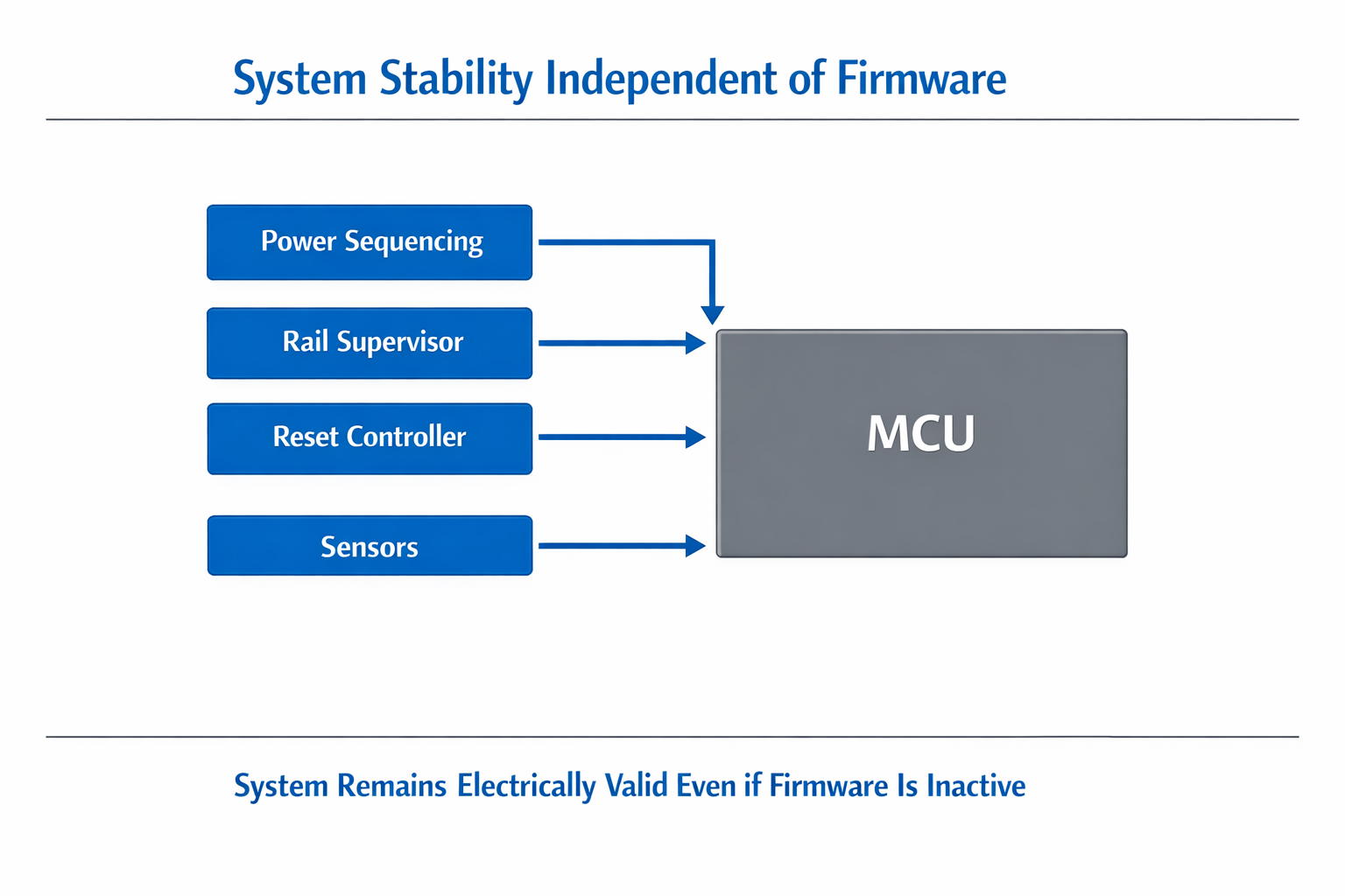
Designing Before Software Exists
The core principle is simple:
The system must behave correctly even if firmware is not running.
If firmware crashes during boot, rails must remain stable.
If MCU resets, sensors must not latch undefined states.
If brownout occurs, restart must be clean.
That is hardware determinism.
Firmware enhances functionality.
It should not be responsible for basic electrical sanity.
The Outcome
This methodology improves:
- Cold-start stability
- Temperature-dependent boot consistency
- Long-term silicon stress reduction
- Bus reliability
- EMI behaviour during ramp
- Debug predictability
- Reduced intermittent startup bugs
It transforms power application from a gamble into a controlled event.
And in embedded sensor systems, control at startup defines everything that follows.