The $2 Decision That Determines 5 Years of Product Life
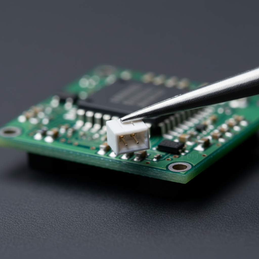
When you're holding a PCB prototype, it's easy to focus on the exciting parts—the microcontroller, the sensors, the wireless module. But here's what I've learned at Hoomanely: the humble connector is often the difference between a product that lasts 5 years and one that fails in 6 months.
Most hardware failures in the field aren't from sophisticated circuit design flaws. They're from the mechanical interfaces—the connectors that experience physical stress every single day of the product's life.
That's why at Hoomanely, we treat connector selection as a critical design decision right from the prototyping stage, not an afterthought during production planning.
Why Connectors Deserve More Respect
Think about what a connector endures over a product's lifetime:
- Battery connectors: Insertion cycles during assembly, service, and battery replacement
- Board-to-board connectors: Thermal expansion and contraction as the device heats and cools
- Cable connectors: Pull forces, vibration, and mechanical stress during use
- Sensor connectors: Potential contamination, humidity exposure, temperature extremes
A connector that seems fine in the lab can degrade significantly after 50 insertion cycles, or fail intermittently after temperature cycling, or develop high contact resistance in humid environments.
These aren't hypothetical problems—they're the most common causes of field failures in IoT and embedded devices.
Our Pre-Production Connector Strategy
Here at Hoomanely, we've developed a systematic approach to connector selection that starts during the initial prototype phase. This prevents expensive redesigns and ensures long-term reliability.
Phase 1: Design Requirements Definition
Before we even open a component catalog, we define clear requirements:
For each connector on the board, we document:
- Expected insertion/removal cycles over product lifetime
- Current and voltage requirements
- Mechanical stress profile (will it see vibration? drops? pulling forces?)
- Environmental exposure (temperature range, humidity, dust)
- Serviceability requirements (user-replaceable? field service? factory only?)
- Space constraints and PCB footprint limitations
This might seem like overkill for a "simple" connector, but it prevents problems before they start.
Example from our recent IoT sensor design:
Battery connector requirements:
- 100+ insertion cycles (field-replaceable battery)
- 2A continuous current capability
- Operating range: -20°C to +70°C
- Must survive 1.5m drop test while connected
- User-accessible, so keying must prevent reverse polarity
This level of specification tells us exactly what we need—not just any battery connector will do.
Phase 2: Component Selection with Long-Term Thinking
At Hoomanely, we've standardized on JST connectors as our primary choice for most applications. This isn't random—it's a strategic decision based on several factors.
Why JST specifically?
Global availability: JST components are stocked by major distributors worldwide. If we need to scale production or switch manufacturing partners, component availability won't be a bottleneck.
Consistent quality: JST provides detailed specifications for insertion cycles, retention force, and environmental ratings—and their products meet those specs reliably.
Complete ecosystem: For each connector family, there are matching wire assemblies, crimp tools, and housings. This simplifies manufacturing and quality control.
Proven track record: JST connectors are used in millions of consumer and industrial products. The failure modes are well-documented, and the reliability is proven.
Standardization benefits: By using JST across product lines, we reduce inventory complexity, streamline manufacturing training, and maintain consistent quality processes.
Our JST connector selection guide:
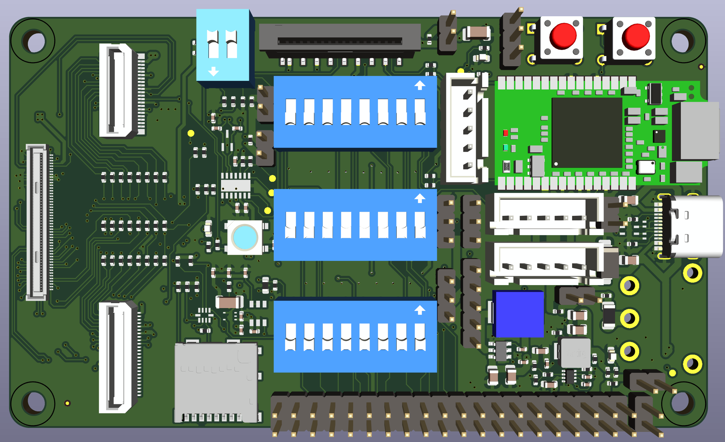
- Battery connections (user-replaceable): JST PH series (2mm pitch) – rated for 20+ cycles, robust housing
- Battery connections (high-current): JST XH series – handles 3A per pin reliably
- Sensor connections (compact): JST SH series (1mm pitch) – excellent for space-constrained designs
- Board-to-board (frequent access): JST ZH series (1.5mm pitch) – good balance of size and durability
The key is matching the connector family to the specific application requirements we defined in Phase 1.
Phase 3: The Three Non-Negotiable Tests
Before any connector is approved for production use at Hoomanely, it must pass our three critical validation tests. We run these during the prototype phase, not after we've committed to manufacturing.
Test 1: Pull Force Validation (Retention Testing)
What we're testing: How much force is required to disconnect the connector, and how this changes over repeated cycles.
Our process:
We use a digital force gauge to measure retention force systematically:
- Measure retention force on new connector (baseline)
- Perform 10 connection/disconnection cycles
- Measure retention force again
- Continue to 25 cycles, 50 cycles, 100 cycles
- Track degradation curve
Acceptance criteria:
- Battery connectors: Minimum 2.0N retention force, less than 30% degradation after 50 cycles
- Board-to-board connectors: Minimum 3.0N retention force, less than 25% degradation after 100 cycles
Why this matters: A connector might feel secure when new, but if retention force drops significantly after just 20 insertions, it will cause intermittent connections in the field. We catch this during prototyping, not after production.
Real example: We tested two battery connectors during our last prototype phase. Both felt equally secure initially. After 50 cycles, Connector A maintained 2.1N retention. Connector B dropped to 0.8N. Guess which one we chose for production?
Test 2: Pinout Safety and Keying Verification
What we're testing: Can the connector be inserted incorrectly? If someone tries to force it wrong, what fails first—the connector or the board?
Our process:
We physically attempt incorrect insertions with increasing force:
- Try reverse polarity insertion (if physically possible)
- Try offset insertion (one position shifted)
- Try forced insertion at angles
- Document what breaks or prevents incorrect connection
Design rules we follow:
• Physical keying is mandatory – No symmetric connectors unless it's electrically safe to reverse
• Ground pins on the outside – If a battery connector somehow gets forced backwards, ground contacts first
• Shrouded headers – Prevent accidental shorts from tools or metal debris during assembly
• Silkscreen markings – Clear polarity indicators that match wire color conventions
• Circuit-level protection – Reverse polarity protection diodes or MOSFETs on critical power inputs
Why this matters: A reversed connector isn't just inconvenient—it can destroy the entire board instantly. Our multi-layer protection approach ensures this never happens in production or field service.
Test 3: Serviceability and Longevity Assessment
What we're testing: Can this connector support the product's entire lifecycle? Can technicians service it? What's the real-world failure mode?
Our evaluation criteria:
Accessibility: Can the connector be accessed without full device disassembly?
Tool requirements: What's needed to disconnect safely? Standard tools or specialized equipment?
Replacement cost: If this connector fails in the field, what's the true cost of repair?
Degradation visibility: Will connector degradation cause sudden failure or gradual performance loss?
Documentation: Can field service technicians identify the correct connector type and orientation?
Why this matters: Serviceability directly impacts total cost of ownership and customer satisfaction.
Our approach at Hoomanely:
We design products where major subsystems use connectors, not permanent soldering:
- Battery: User-replaceable with basic tools (JST PH connector)
- Sensors: Field-serviceable by trained technicians (JST SH/ZH connectors)
- Communication modules: Replaceable without specialized equipment
- Antennas: U.FL for internal, SMA for external—both field-replaceable
This philosophy has tangible benefits:
Here it is with dotted bullet points instead of tick marks:
- Faster prototyping: We can swap modules during development without PCB rework
- Flexible manufacturing: If component sourcing issues arise, we can substitute modules without scrapping assembled boards
- Reduced returns: Many "failed" devices are actually depleted batteries or single faulty sensors—easy fixes instead of full replacements
- Extended product life: A device that can be serviced lasts years longer than one designed as disposable
Phase 4: Environmental Stress Testing
Even the best connector can fail under environmental conditions. Before finalising our design, we subject prototype assemblies to real-world stress testing.
Our standard environmental test protocol:
Temperature cycling: -20°C to +70°C, 10 complete cycles, with electrical continuity monitoring
Humidity exposure: 85% relative humidity, 48 hours, followed by electrical resistance measurement
Vibration testing: For portable devices, 2 hours on shake table simulating transport and handling
Drop testing: 1.5m drops onto a hard surface, 6 orientations, with connectors mated
After each test, we measure:
- Contact resistance (should remain under 50mΩ)
- Retention force (should not degrade more than 30%)
- Visual inspection for cracks, corrosion, or deformation
If a connector fails any of these tests during prototyping, we redesign before manufacturing tooling begins.
The Systematic Advantage
This comprehensive connector validation might seem time-intensive, but here's what it delivers:
Predictable reliability: We know exactly how our connectors will perform over the product lifetime
Reduced field failures: Connector issues are caught in the lab, not reported by customers
Faster time-to-market: No delays for redesigns after manufacturing begins
Lower warranty costs: Products that don't fail in the field don't generate expensive warranty claims
Better customer experience: Devices that work reliably build brand reputation and customer loyalty
At Hoomanely, we view connector selection and validation as an investment in product quality, not a cost to minimise.
The Documentation That Matters
For each connector approved for production, we maintain detailed documentation:
- Selection rationale (why this connector for this application)
- Test results (retention force over cycles, environmental stress data)
- Assembly instructions (crimping procedure, insertion force requirements)
- Quality control criteria (what to check during manufacturing)
- Service procedure (how to safely replace in the field)
This documentation becomes part of our manufacturing package, ensuring consistency across production batches and manufacturing partners.
Quick Reference: Connector Selection Framework
When starting your next hardware design, ask these questions:
Application Analysis:
- How many insertion/removal cycles will this connector see?
- What current and voltage must it handle?
- What environmental conditions will it experience?
- Does it need to be user-serviceable or field-serviceable?
Component Selection:
- Does the connector have adequate retention force specifications?
- Is physical keying robust enough to prevent incorrect insertion?
- Are components available from multiple distributors globally?
- Does the manufacturer provide detailed reliability data?
Validation Testing:
- Have you measured retention force over expected cycle count?
- Have you attempted incorrect insertions to verify keying?
- Have you tested under environmental stress conditions?
- Have you documented the failure modes?
Manufacturing Planning:
- Are assembly instructions clear and complete?
- Do you have the correct crimping tools for production?
- Have you defined quality control inspection criteria?
- Is the connector compatible with your CM's equipment?
The Long-Term Perspective
At Hoomanely, we're building products designed to last. That means thinking beyond the initial prototype demo and considering what happens in year 3, year 4, and year 5 of the product's life.
Connectors are mechanical components that wear over time. By selecting high-quality connectors, testing them systematically during prototyping, and designing for serviceability, we ensure our products maintain reliability throughout their entire lifecycle.
This approach has become a cornerstone of our reputation for quality. Customers notice when devices simply keep working, connection after connection, year after year.
That reliability isn't luck. It's the result of making the right $2 decision during the prototype phase, backed by systematic testing and validation.


