The Battery Whisperer's Guide: Squeezing Every mAh from Your Tracker
Building a tracker with Wi-Fi, Bluetooth, LoRa, and GPS doesn’t have to mean living on a charger. In this write-up, I’ll walk through the exact moves that took our ESP32-S3 design from “dies by dinner” to “runs for weeks”—from hunting down sneaky “always-on” leaks to letting each radio speak only when it truly should.
You’ll see how we establish a truthful power baseline (not the brochure numbers), carve the hardware into sane power domains, and schedule radios with intent—GPS fixes gated by motion, Wi-Fi sessions that reconnect fast and sleep deeper, and LoRa that adapts to link quality instead of blasting at a fixed spread factor. We’ll go into deep sleep as the default, use the ULP for cheap background sensing, and hard-gate peripherals so “standby” currents don’t quietly drain your pack.
The Hidden Power Vampires: Understanding Your Baseline
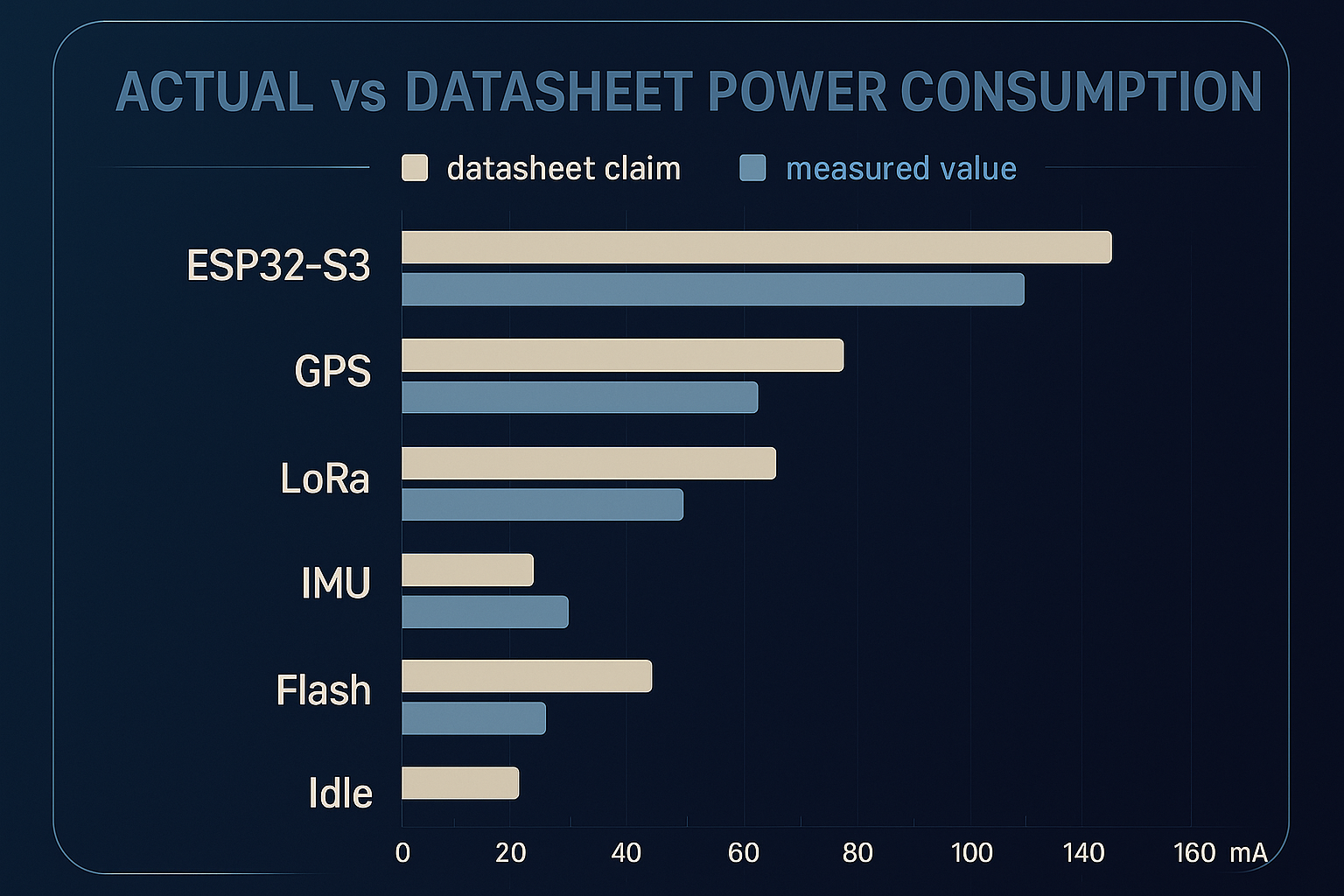
Start with measurement, not brochures. It’s common for a “50 μA sleep current” target to land closer to 850 μA once the whole stack—rails, sensors, and radios—is assembled. Every unmeasured path is a quiet drain on the pack, so the first win is a truthful baseline.
Three culprits worth auditing early:
- GPS backup/standby rail (~150 μA): Many GNSS modules keep a backup domain alive. Treat it as a separate load—gate it with a load switch or ensure it’s only powered when fast reacquisition is truly needed.
- Regulator quiescent & reverse leakage (~200 μA): Some LDOs behave beautifully under load but sip more than expected at idle. Check Iq across temperature and voltage, verify reverse isolation, and pick parts per rail role (burst-friendly on the main rail, ultra-low-Iq on always-on).
- I²C pull-ups into unpowered sensors (~500 μA): If pull-ups sit on an always-on domain while devices are power-gated, current can back-feed through protection diodes. Place pull-ups on the same domain as the sensors, or add bus switches/FET gating.
A quick procedure to nail the baseline:
- Partition by domain: Always-on, sensors, radios.
- Measure at the battery and per rail: Use an inline meter or power profiler; sample across key states (shipping mode, deep sleep, sample, transmit).
- Toggle domains deliberately: Disable one domain at a time in firmware or with hardware jumpers/switches; log the delta.
- Validate “sleep” truly sleeps: Issue deep-power-down commands to Flash, verify IMU low-power modes, and confirm wake sources (RTC/GPIO/ULP) don’t spuriously fire.
- Record before/after in a table: μA and mAh per state, with conditions (voltage, temperature, firmware hash).
Cleaning up just these baseline leaks often transforms endurance—think an idle estimate moving from ~98 days to ~545 days—before any higher-level scheduling or radio logic is applied. Establish the baseline once, keep it in CI with a smoke test, and let everything else build on numbers you trust.
Architecture for Micro-Power: The Foundation
Think in power domains, not just peripherals. A simple three-domain layout keeps control clean and measurable:
- Always-on: ESP32-S3 + RTC domain on an ultra-low-Iq LDO (e.g., TPS7A05 @ 25 nA).
- Sensor domain: IMU, barometer, microphone behind a P-MOSFET load switch.
- Radio domain: GPS and LoRa on independent enable lines for selective bring-up.
This structure lets you cut power completely to entire blocks instead of relying on “standby” modes. For example, a microphone AFE that idles at ~50 µA is inexpensive per second but costly over time; hard-gating it saves ~1.2 mAh per day, which compounds over multi-week runtimes.
Regulators matter as much as topology. Match each LDO to the rail’s behavior. Ultra-low-Iq is ideal on always-on rails, but bursty 3.3 V radio rails can see ~250 mA peaks where transient performance dominates. Choosing a transient-strong LDO with a modest Iq (≈50 µA vs ≈1 µA) prevents dropout, ripple, and slow recovery—shortening TX windows, avoiding retries, and delivering on the order of ~15% net battery savings when radios drive the duty cycle.
Radio Discipline: The 80% Solution
Radios make or break your battery. And it's not just how often you use them—it’s how intelligently you time them.
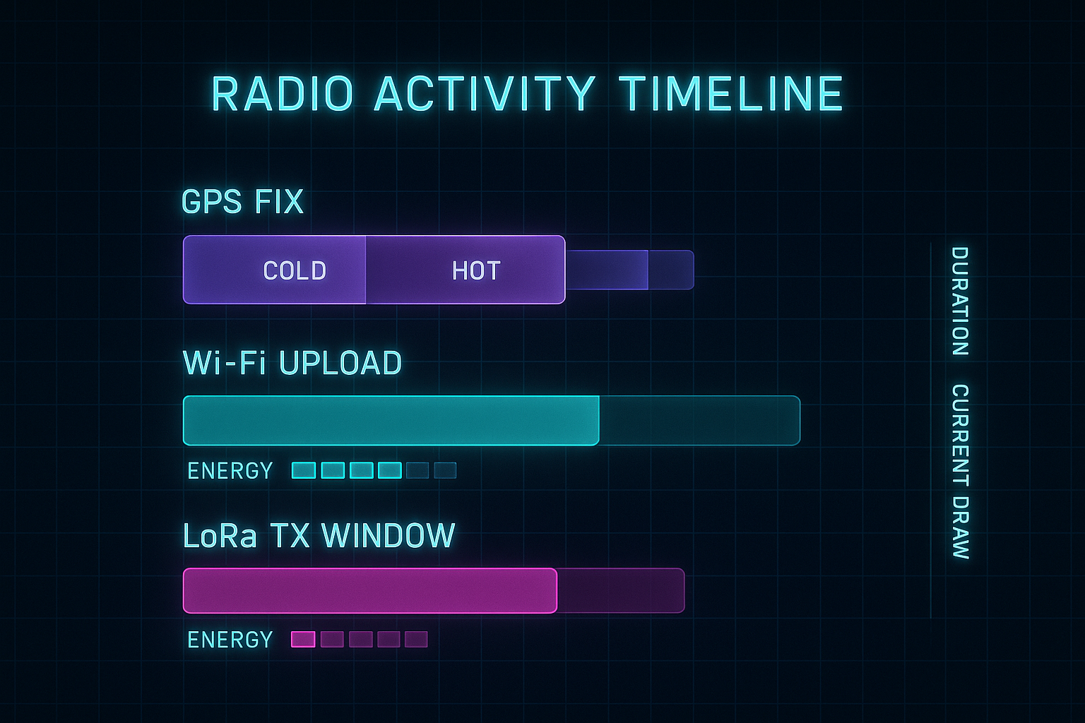
- GPS: Cold starts took up to 90s at 42mA. We implemented AGPS preload over Wi-Fi, stored ephemeris in RTC RAM, and used IMU data to throttle fix rates. If the dog wasn’t moving, no GPS. If it sprinted, faster fixes kicked in.
- Wi-Fi: Static IP, DNS caching, and DTIM interval control dropped our reconnect time from 5s to 1.6s. Connection reuse beat aggressive polling. For infrequent updates, we disconnected fully. For fast syncs, we stayed in modem sleep.
- LoRa: We dynamically tuned SF7–SF10 based on RSSI/SNR. This cut our TX power by up to 70% on short-range syncs. We logged SNR metrics and adapted on the fly. No more always-on SF10 "just in case."
Our radio state machine became smarter than our state diagram. Motion-gated GPS, battery-aware Wi-Fi upload intervals, and fallback logic for LoRa-only fallback when other radios failed.
MCU Power States: The Deep Sleep Religion
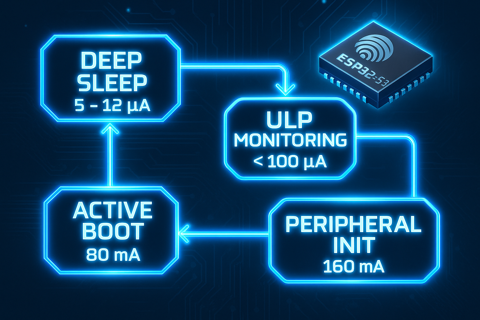
The ESP32-S3 deep sleep mode is the only mode that matters in low-duty devices. We achieved 11μA baseline draw using:
- RTC Timer + GPIO interrupt for scheduled and reactive wake
- ULP coprocessor running sub-5kHz polling loop (battery voltage + IMU event)
Wake intervals were tuneable based on activity. During periods of user motion (via IMU), the RTC timer fired every 2 minutes. In inactivity states, we backed it off to 10 or even 30 minutes.
The ULP let us avoid full wakeups entirely for 50–75% of cycles. Its 150μA active draw, running at 1% duty cycle, cost less than 2μA average.
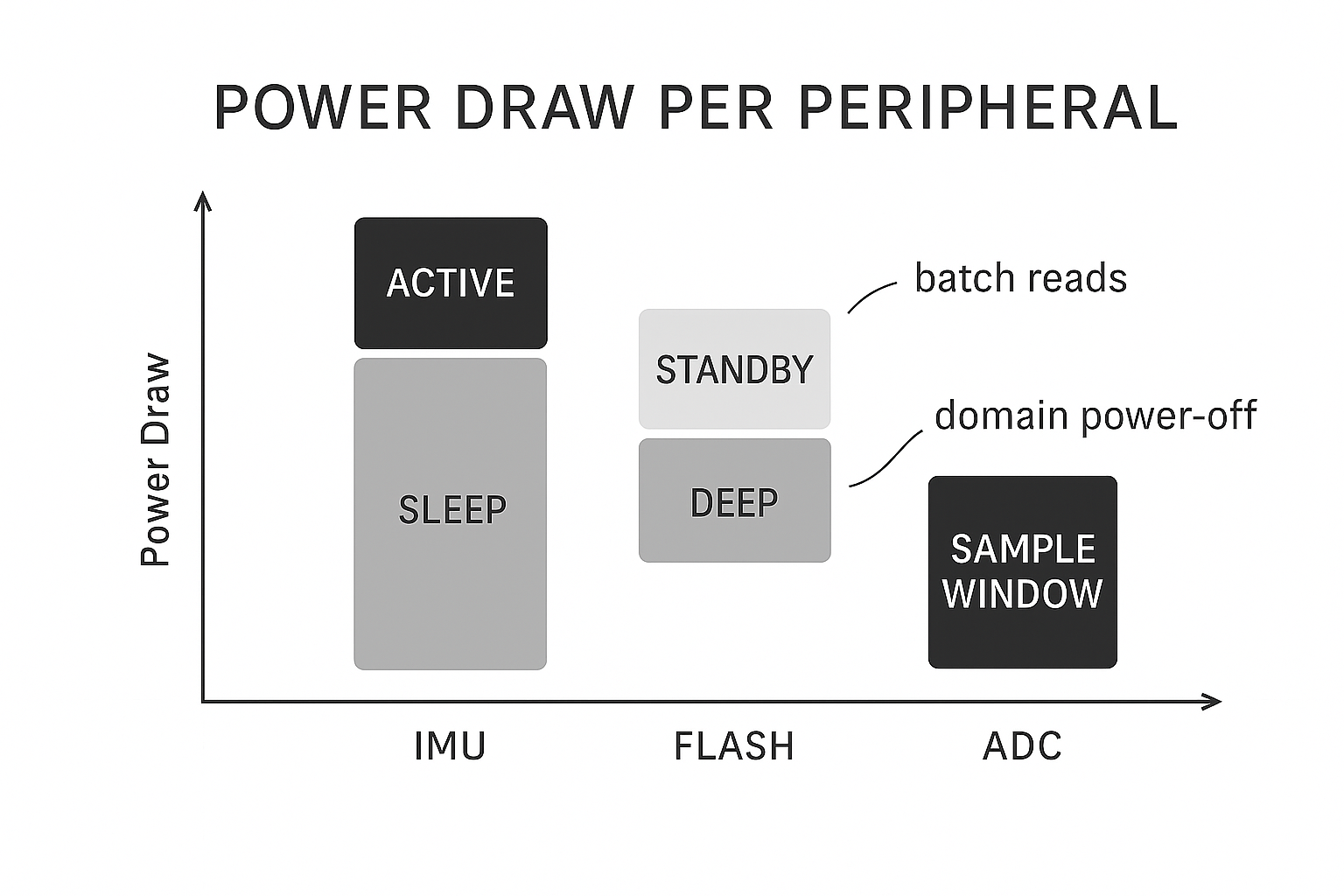
Sensors and Peripherals: Death by a Thousand Cuts
Peripherals are sneaky. One 50μA standby line doesn’t seem much—until you multiply it by three sensors, 24 hours, and 15 days.
Our IMU runs in accelerometer-only mode most of the time (8μA). Full 9-axis activation is conditional: real movement or a calibration window.
And audio? Off by default. We power it via MOSFET only for 2-second windows during specific user-defined scenarios (barking analysis, sound classification).
Firmware Architecture: Orchestrating Efficiency
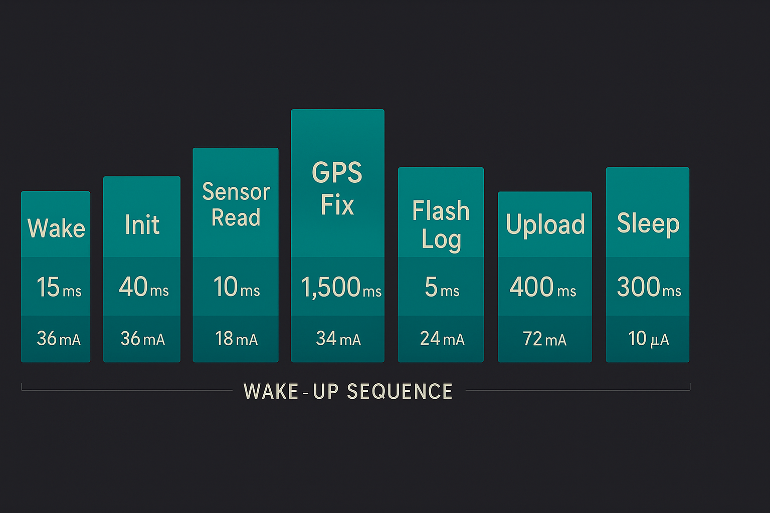
Firmware is the glue between all these savings. Our scheduler divides each wake cycle into discrete slices:
- RTC Restore + Wake Source Check
- Fast Sensors (IMU, barometer)
- Decision Tree: GPS Fix?
- Logging
- Transmit (Wi-Fi/LoRa)
- Store context + Sleep
All blocking ops (e.g. GPS acquisition) have hardcoded timeouts. If GPS doesn’t fix in 60s, we drop. If Wi-Fi isn’t connected in 10s, we defer.
Everything adapts:
- Battery < 3.4V? Radio updates drop to once/hour.
- No motion? Skip GPS.
- Flash full? Switch to low-resolution logging.
Charging System Optimization
Charging should be smart—not fast. Our charger runs at 300mA, maximizing lithium battery longevity. Thermistor-controlled charge cutoffs at >45°C avoid thermal degradation.
We also disabled charge during radio-intensive sessions. Flash writes + GPS + charging = heat + brownouts. Better to charge gently when idle.
Key Takeaways
- Measure aggressively
- Use deep sleep or nothing
- Treat GPS like a tiger: powerful, expensive, timing-sensitive
- Schedule radios like a network architect
- Use ULP as a real processor, not an afterthought
- Power off what you don’t need—literally
- Build firmware to adapt, fail gracefully, and recover predictably
Everything here was built to support Hoomanely’s core goal: seamless, non-invasive devices. We build systems that stay quiet when they should, alert when they must, and never ask users to micromanage charge cycles.
This battery-first design flows into all of our work—from environmental sensors to wellness wearables. The same architecture that lets a pet tracker last weeks is what will someday let a health patch run a full recovery cycle, or an environmental monitor live untethered for months.
This guide represents hundreds of hours of profiling and refinement. If you're building similar systems, these lessons are yours to borrow, remix, or improve upon. The best battery optimisation happens in the field, not the lab. Let's push the limit of what small power can do.


